Design of a CO
2
heat pump drier with dynamic modelling tools
Michael JOKIEL(a), Michael BANTLE(a), Christian KOPP(a), Ingrid C. CLAUSSEN(a), Ignat
TOLSTOREBROV(b)
(a) Department of Energy Processes, SINTEF Energy Research, NO-7465 Trondheim, Norway, [email protected]
(b) Norwegian University of Science and Technology, Department of Energy and Process Technology, 7465 Trondheim, Norway
ABSTRACT
Drying is an energy and time intensive process which thermal energy demand is mostly provided by fossil resources. Especially in the food processing industry it is important to increase the energy efficiency of drying processes in terms of organic products and sustainability. The potential of using a heat pump with R744 (CO2) as a working media to provide the thermal energy was investigated
for typical food drying temperature of 50 °C at a relative humidity of 20 %. A dynamic heat pump-assisted dryer model has been developed and validated. The model was created with respect to heat transfer, pressure loss and flow requirements. The simulated results showed that a closed-loop heat pump assisted drying process has the potential to reduce the energy demand by around 80 % compared to conventional open-loop drying processes with fossil resources as energy source. Furthermore, the implementation of a bypass in the air cycle was examined to further enhance the energy efficiency of the system.
Keywords: Heat pump, Modelica, simulation, convective drying, CO2, food drying
1 INTRODUCTION
[image:1.595.73.422.486.738.2]The process of drying is widely-used in all kind of industries and is a very energy consuming process. It is estimated that about 12 % of the total energy used in industries is used by drying processes (Strumillo et al. 2014), whereas the major amounts are demanded by the food and paper industries.
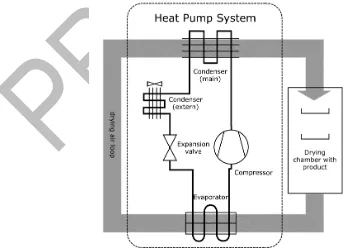
In addition, convective drying based on air as drying agent is the most common used drying technology with around 85 % (Atuonwu et al. 2011). With this big percentage in energy demand, it is not surprising that the process of drying has been, and still is a very important field of research in terms of energy efficiency and product quality. In this study, a heat pump driven model of a convective food drier was developed as shown in the scheme in Figure 1. The energy efficiency of the heat pump driven dryer was then compared with other conventional methods. The basic advantages of heat pump driven convective drying results from the ability to recover energy from the used drying air and reuse it in the process. This results in one of the highest specific moisture extraction ratio (SMER), often between 1 to 4 since the heat can be recovered from the moist air (Chou et al. 2006). This can result in a drying efficiency of up to 95 % compared to 30 - 40 % for other hot air drying methods (Perera & Rahman, 1997). Industrial heat pumps with a heat sink of up to 100 °C using natural refrigerants (R717, R718 and R744) are already conventionally established which makes heat pumps very suitable for drying of food which is usually performed at temperature levels up to 70 °C.
2 MAIN SECTION
The present study investigates different system designs for closed-loop drying processes that have been enhanced with a heat pump, using R744 as refrigerant. To evaluate the potential increase of energy efficiency, an open loop drying process with a fossil fuel-based burner serves as a benchmark. The validation was conducted with measurement data from an actual drying system. 2.1 Modelling the drying chamber
The drying chamber model has been implemented in Modelica using already existing model libraries, TIL and TIL Media (Gräber et al. 2010). TIL is a model library for thermal components and systems, while TIL Media contains a model library including thermophysical properties for the utilized fluids The newly derived model consists of a volume cell representing the drying chamber, where the drying product is exposed to the moist air. The model focusses on the heat and mass transfer between the incoming moist air, the product that is to be heated and dried, and the outgoing moist air.
The model for the drying chamber is connected to the rest of the system via two gas ports for in- and outgoing moist air. Heat and mass transfer quantities are calculated with the help of the corresponding coefficients: The heat transfer coefficient α is calculated based on convective heat transfer (Baehr 2003) according the following equations:
utilizing the dimensionless flow quantities of the Reynolds number 𝑅𝑅𝑅𝑅 and Prandtl number 𝑃𝑃𝑃𝑃. Since flow conditions in the range between laminar and turbulent flow are existing, the Nusselt number is averaged by equation (3)
Finally, the heat transfer coefficient is calculated by equation (4)
The mass transfer coefficient β is essentially based on the same principles, combined with the film theory for mass transfer, taken from (Baehr 2003):
𝑁𝑁𝑁𝑁𝑚𝑚,𝑡𝑡𝑡𝑡𝑡𝑡𝑡𝑡= 0,037𝑅𝑅𝑅𝑅 0,8𝑃𝑃𝑃𝑃
1 + 2,443𝑅𝑅𝑅𝑅−0,1(𝑃𝑃𝑃𝑃2 3⁄ −1)
Eq. (1)
𝑁𝑁𝑁𝑁𝑚𝑚,𝑙𝑙𝑙𝑙𝑚𝑚 =√𝜋𝜋2 𝑅𝑅𝑅𝑅1/2∗ 𝑃𝑃𝑃𝑃 1 2⁄
(1 + 2,55𝑃𝑃𝑃𝑃1 4⁄ + 48,66𝑃𝑃𝑃𝑃)1 6⁄
Eq. (2)
𝑁𝑁𝑁𝑁𝑚𝑚 =�𝑁𝑁𝑁𝑁𝑚𝑚,𝑙𝑙𝑙𝑙𝑚𝑚2 +𝑁𝑁𝑁𝑁𝑚𝑚,𝑡𝑡𝑡𝑡𝑡𝑡𝑡𝑡2
Eq. (3)
with considering the empiric Lewis-factor 𝐿𝐿𝑅𝑅. Furthermore, properties of the drying product needs to be provided as input parameters. Property data like heat capacity for liquid water is provided by a temperature and pressure dependent object class. However, for the moist air two of these object classes are utilized to consider the special conditions in the drying chamber: One pressure and enthalpy dependent moist air object that represents the incoming dry and hot air and one pressure and temperature dependent air object that calculates the property data of the moist air directly at the surface of the drying product. It is assumed that the air on the product surface features the same temperature as the product and is considered as saturated air with a relative humidity of 100 %. Combining the quantities outlined above, the mass flow rate for the water that is being removed of the product over the time can be calculated, based on film theory for mass transfer (H.D. & K., 2003):
with 𝑀𝑀� as the molar mass of water and air, 𝑅𝑅𝐵𝐵 as the specific gas constant, 𝑥𝑥𝑥𝑥 as the mass fraction and 𝑎𝑎 as the activity coefficient, which considers the decelerated mass transfer at the end of a drying process when the capillary forces are limiting the water release from the product (Deans, 2001). The activity factor is characteristic for each type of product and needs to be measured.
For the drying chamber model, the usual energy and mass balances are augmented with equation (7), which considers the progress of the drying:
The modelling of the dryer cell was conducted in an object-oriented way with the potential to theoretically investigate various different drying products. That way, the standalone cell can be universally implemented in both open-loop or closed-loop drying processes.
2.2 Validation of the model
The model for the drying chamber is validated against measurement data which was provided by Innotech GmbH, a German manufacturer of drying systems. The validation is conducted with two types of measurement data sets, which differ in the general scaling of the drying processes.
[image:3.595.53.543.557.727.2]The model was provided with measured input parameters for the inlet relative humidity, the air velocity in the drying chamber and the inlet temperature of the moist air according Table 1.
Table 1: Measurement data for apple drying, provided by Innotech GmbH
Mass of product 3 kg 100 kg
Drying temperature 55 °C 70 °C
Inlet relative humidity 16 % 10 %
Outlet relative humidity 40 % -
Moist air volume flow 0.07 m³/h 5500 m³/h
Moist air velocity 1.3 m/s -
Drying time 8 h 8 h
Removed water - 15-20 kgH20/h
Figure 2 (left) shows the successful simulation of the drying curve for the small-scaled system, with a maximum deviation of 10 % between the measurement and the model. For the large-scaled
𝛽𝛽=𝛼𝛼 ∗ 𝐿𝐿𝑅𝑅𝜌𝜌 ∗ 𝑐𝑐
𝑝𝑝
Eq. (5)
𝑚𝑚̇=𝑀𝑀�𝑤𝑤𝑙𝑙𝑡𝑡𝑤𝑤𝑡𝑡 𝑀𝑀�𝑙𝑙𝑎𝑎𝑡𝑡 ∗
𝑝𝑝
(𝑇𝑇 ∗ 𝑅𝑅𝐵𝐵)∗ 𝛽𝛽 ∗ 𝐴𝐴 ∗ 𝑎𝑎 ∗(𝑥𝑥𝑎𝑎,𝑠𝑠𝑠𝑠𝑠𝑠− 𝑥𝑥𝑎𝑎,𝑖𝑖𝑖𝑖𝑖𝑖𝑖𝑖𝑠𝑠)
Eq. (6)
𝑑𝑑𝑚𝑚
𝑤𝑤𝑑𝑑𝑑𝑑
=
−𝑚𝑚̇
measurement of 100kg apples in figure 2 (right), it is measured that five hours after the drying process has started, 70kg of water has been removed from the product, which has been correctly estimated by the model. Therefore, the model reproduces the system behaviour for both measurement data sets in an accurate way and can be thus considered successfully validated.
Figure 2: Drying of initially 3kg (left) and 100kg (right) of apples, measurement Innotech GmbH vs Modelica model
2.3 Implementation of a heat pump
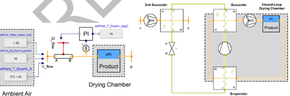
The final aim of this study is to utilize the validated model of the drying chamber to evaluate heat pump-assisted drying systems. To be able to make more precise statements on the energetic efficiency of a drying process, various system setups are investigated in this section: A benchmark open-loop system without heat pumps, a simple heat pump system with two gas coolers and a more elaborated heat pump system with two evaporators. Furthermore, the effect of direct recirculation of moist air by usage of a bypass will be examined.
The simplest system for a drying process is an open-loop process, where ambient air is heated via a fossil fuel burner and being released to the environment after passing the drying chamber, as depicted in figure 3 (left). The general requirements to the system regarding components or control schemes are low. As for the model, ambient air of 25 °C is sucked in and heated up with approximately 80 kW to keep the inlet temperature at 70 °C.
Figure 3: Main components of the simulated open-loop benchmark setup (left) and the simulated heat pump drying process with R744 (right)
However, to increase the energy efficiency of any drying process, a closed-loop system for the moist air is a promising setup to lower energy consumption. The amount of heating load that is required to provide a specific drying temperature can be decreased by re-utilization of the still hot air from the drying chamber outlet. Therefore, a heat pump with CO2 (R744) as refrigerant is used, as shown in
[image:4.595.66.535.507.663.2]temperature. First, the air is cooled down in the evaporator to enforce condensation and remove moisture. Afterwards, it is reheated again by the gas cooler to provide relatively dry hot air to the drying chamber.
[image:5.595.172.499.198.384.2]In the CO2-cycle a second gas cooler is required. On one hand to ensure an efficient CO2-cycle with crossing the critical point before the following expansion in the valve, on the other hand to dispose excess heat: surplus heat is introduced into the heat pump system via the compressor load, and since drying is an isenthalpic process and since the moist air cycle is a closed-loop system, an additional heat sink is needed. Figure 4 shows a CO2 heat pump cycle in a temperature-entropy diagram, with the corresponding cooling and re-heating of the moist air for humidity removal in the evaporator.
Figure 4: Heat pump assisted drier with R744 for a drying temperature of 50 °C
Furthermore, an assessment of the control variables for the system in figure 3 (right) shows that a second evaporator might be beneficial: The load of the second gas cooler is controlled by the speed of the fan to control the inlet temperature to the valve. The valve position is controlling the high pressure and the compressor speed is used to control the inlet temperature to the drying chamber. The moist air fan is providing a constant volume flow. Therefore, there is a lack of a control variable to control the low pressure of the CO2-cycle and thus the evaporator load. This leads to the
introduction of a second evaporator arranged in a parallel setup, as shown in figure 5 (left).
[image:5.595.72.502.515.734.2]The last system setup that is evaluated in the next section features the implementation of a moist air bypass within the closed-loop cycle. A direct recirculation of 20 % and 50 % of the overall moist air volume flow will be examined. The percentage of recirculation is adjusted by choosing appropriate pressure drop values for the tubes in the bypass and evaporator circuit. By reducing the volume flow in both the evaporator and gas cooler, less energy consumption is expected due to a reduced compressor load. Any of the previously introduced systems could be equipped with a bypass on the air side. A simplified scheme of the system layout is illustrated in figure 5 (right), for reasons of clarity with a cut-off heat pump.
2.4 Simulation results and outlook
Three different system setups for a heat pump assisted dryer are investigated regarding their quantity of energy savings in comparison towards an open-loop benchmark setup. The heat pump system with two parallel evaporators (figure 5 (left)) will in the following be referred to as "No Bypass". Furthermore, this system will be upgraded with a bypass, which enables a 20 % and 50 % direct recirculation of the overall moist air flow. Therefore, four system designs are compared in figures 6-8.
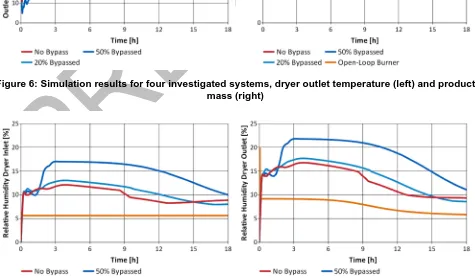
[image:6.595.66.534.344.517.2]The investigated systems are based on a dryer capacity which provides the removal of up to 7 kg water per hour at the considered drying conditions. The inlet temperature for the drying chamber has been controlled to 50 °C for all four systems. For the open-loop system, the moist air is just being released to the environment. For the three heat pump-assisted systems, the moist air is cooled down in the evaporator to 30 – 35 °C, depending on the amount of bypassed air, as seen in figure 6 (left):
[image:6.595.62.537.449.727.2]Figure 6: Simulation results for four investigated systems, dryer outlet temperature (left) and product mass (right)
If the end of the drying process is defined with 70 kg of water that has been evaporated from the initial 100 kg of apples, then the following times are needed to finish the drying: "Open-loop Benchmark" 11.7 h, "No Bypass" 13.6 h, "20 % Bypass" 14.5 h and "50 % Bypass" 16.8 h, as illustrated by figure 6 (right) The required drying time is the shortest for the open-loop benchmark system, as relatively dry air is heated and fed to the drying chamber. The circulation of air within a closed-loop setup leads to a higher relative humidity and thus extended drying times (figure 7). Relatively, the utilization of heat pumps leads to an increase in time by 13 – 43 % regarding the setup.
The COP for all three heat pump-assisted systems is approximately 3.2, with a gas cooler to compressor load ratio of 𝑄𝑄̇
𝑃𝑃𝑐𝑐𝑐𝑐𝑐𝑐𝑐𝑐𝑐𝑐 [kW/kW] = 29/9 for "No Bypass", 25/8 for "20 % Bypass" and 18.5/6
for "50 % Bypass". The heat supply of the "Open-Loop Burner" was 56 kW.
[image:7.595.173.527.260.482.2]The process efficiency was evaluated through the specific moisture evaporation rate (SMER) for the drying process, which states how much water can be removed from the product with the utilization of 1 kWh. The SMER is defined by
Figure 8: Simulation results for four investigated systems, comparison of the specific moisture evaporation rate (SMER)
In the examined temperature range, the latent heat of water evaporation is 0.63 kWh (2250 kJ). This amount of energy is required to evaporate 1 kg of water, leading to a reciprocal value of 1.6 kg/kWh. Therefore, figure 8 shows that the SMER for the open-loop benchmark system is quite low in comparison to typical values for the SMER than can be found in literature (Chou et al. 2006). This indicates rather inefficient drying conditions and a product that is difficult to dry (in this case apples, with an initial moisture content of approximately 80 %).
The implementation of a heat pump has the potential for energy related savings of 80 % in comparison to the examined benchmark process, which can be even increased with the usage of a bypass. Since the open-loop benchmark system was operated without a bypass, the evaluation of the bypass cycles should be referred to the "No Bypass"-system, to highlight the impact of the bypass utilization towards the same general system setup. Therefore, in comparison to the "No Bypass"-system, the "50 % Bypass"-system offers a decrease in energy consumption by 28 %, but also an increase of the drying time by 24 %.
It should be noted that the investigated bypass systems were not optimally controlled in this study, leading to a constant recirculation of moist air and thus, to a non-optimal utilization of the bypass. An adequate control strategy to address the varying heat demand during a typical drying process provides potential for further energy and time savings.
The loss of heating load in the second gas cooler was not considered in the calculations for energy consumption. To further improve the SMER of the heat pump-assisted drying, the heat losses to the environment through the second gas cooler could be cut by applying an on/off regulation in case the drying temperature is getting to high due to the surplus heat from the compression work.
Generally, the heat transfer properties between CO2 and moist air are a limitation towards the overall
system efficiency. The application of intermediate water or glycol sub-cycles between the heat pump and the drying loop could enhance the overall heat transfer and provide more control in adjusting the dryer inlet temperature, with the utilization of water tanks to store heat and cold, respectively.
3 CONCLUSION
A dynamic model for the drying chamber was developed in Modelica to demonstrate the potential energy saving for drying processes at common food drying temperatures. The model allows better understanding of the drying characteristics of the heat pump assisted drying system and enables more sophisticated dimensioning and design of future drying systems. The simulation results were successfully validated towards measurement data.
The simulations show that the desired drying conditions can be reached with the suggested R744 heat pump system. It has been shown that the utilization of a heat pump to provide heating and cooling for a drying process can increase the energetic efficiency by up to 80 % but results in an increased drying time by 13 – 43 %. Furthermore, a variation of the heat pump system design holds further improvements in efficiency. A bypass for direct recirculation of moist air was investigated to decrease the loads in gas cooler and evaporator, providing energy savings of 28 % but demanding a drying time increase by 24 %. A second evaporator was introduced to control the low pressure and thus the evaporator load and water drain.
Further studies are especially required in the overall control of the heat pump system. As indicated, a more sophisticated dynamic control for the bypass mass flow offers great potential for further optimizations during the different phases of the drying process, especially regarding the energy consumption.
ACKNOWLEDGEMENTS
The work was supported by the Research Council of Norway, grant 286127 – Core Organic Cofund: SusOrgPlus project as part of the ERA-NET action CORE Organic Plus. The authors acknowledge the financial support for this project provided by transnational funding bodies, being partners of the H2020 ERA-net project, CORE Organic Cofund, and the cofund from the European Commission.
REFERENCES
Atuonwu, J. C., Jin, X., van Straten, G., Deventer Antonius, H. C. v., & van Boxtel, J. B. (2011). "Reducing energy consumption in food drying: Opportunities in desiccant adsorption and other dehumidification strategies", Procedia Food Science, 1, 1799-1805. doi:https://doi.org/10.1016/j.profoo.2011.09.264
Baehr, H.D., K. Stephan (2003). "Wärme- und Stoffübertragung", 7. Auflage, Springer Verlag Chou, S.K., C. Kian Kiang, and Jon, 47 Heat Pump Drying Systems. 2006.
Deans, J. (2000). "The modelling of a domestic tumbler dryer" Applied Thermal Engineering 21 (2001), 977-990
Gräber, M., K. Kosowski, C. C. Richter and W. Tegethoff (2009). "Modelling of heat pumps with an object-oriented model library for thermodynamic systems " Proceedings Mathmod 2009, Vienna, Austria: 1396-1404.