SUPERVISOR DECLARATION
“I hereby declare that I have read this thesis and in my opinion this report is sufficient in terms of scope and quality for the award of the degree of
Bachelor of Mechanical Engineering (Automotive)”
SECOND SUPERVISOR DECLARATION
“I hereby declare that I have read this thesis and in my opinion this report is sufficient in terms of scope and quality for the award of the degree of
Bachelor of Mechanical Engineering (Automotive)”
ii
DECLERATION
“I hereby declare that the work in this report is my own except for summaries and quotations which have been duly acknowledged.”
Signature : ...
iii DEDICATION
iv ACKNOWLEDGEMENT
In this Final year report, I would like thank my supervisor, Mr. Muhd Ridzuan for helping me a lot in doing this report. Start from the beginning, Mr. Ridzuan give me a clear view about my title and teach me how to start a project. Mr. Ridzuan also teaches me how to prepare a good technical report, in the aspect of formatting and content.
Secondly, I would like to thanks my colleague from BMCA, and Formula Varsity the Leopard team. They have put a lot of effort in the Formula Varsity competition and help me collect a lot of useful data during the vehicle development stage and racing stage.
Furthermore, I would like to appreciate my friend from University Technology Malaysia who helps me to obtain the SAE technical paper from their library. Without their help, I may not have enough reference to do my report.
Last but not least, I would like to thank the resource in UTeM library database and the resource on the World Wide Web. This online data help me a lot in define the topic and title.
v Abstract
vi Abstrak
vii TABLE OF CONTENT
CHAPTER TOPIC PAGE
DECLARATION ii
DEDICATION iii
ACKNOWLEDGEMENT iv
ABSTRACT v
ABSTRAK vi
TABLE OF CONTENT vii
LIST OF FIGURES x
LIST OF TABLES xii
LIST OF SYMBOLS xiii
LIST OF ABBREVIATIONS xiv
CHAPTER 1 INTRODUCTION 1
1.1Introduction of the project 1
viii
1.3 Problem Statement 3
1.4 Scope 3
CHAPTER 2 LITERATURE REVIEW 4
2.1 Formula Varsity 4
2.1.1 History of the Formula Varsity 4
2.1.2. Design Rules 6
2.2 Disc Brake 7
2.2.1 Rotor Design 7
2.2.2 Operation of Disc Brake 9
2.3 Thermal Analysis 11
2.3.1 Thermal / Heat capacity 11
2.3.2 Thermal Stress 12
2.4Finite Element Analysis 13
2.4.1 Background 13
2.4.2 Definition of FEA 13
CHAPTER 3 METHODOLOGY 16
3.1 Formulas Used in the Manual Calculation 17 3.2 Procedure of Heat Transfer Analysis in
ABAQUS Software 19
3.3 Procedure of Coupled
ix
3.4 FE Analysis Parameters 31
3.5 Material Selection 32
CHAPTER 4 RESULTS AND DISCUSSION 34
4.1 Heat Transfer Analysis
4.1.1 Result of Manual Calculation 34 4.1.2. Result of ABAQUS Analysis 36
4.1.2.1 Temperature distribution
on the brake disc surface 38 4.2. Coupled Temperature-Displacement Analysis
4.2.1 Result of Manual calculation 42 4.2.2 Result of Thermal stress in FE analysis 44
4.2.2.2 Thermal Stress Distribution
Of Disc Brake Rotor 46 4.3 Discussion
x CHAPTER 5 CONCLUSION AND RECOMMENDATION 54
5.1 Conclusion 54
5.2 Recommendation 55
REFERENCES 56
APPENDIX A Gantt chart for PSM 1 63
xi LIST OF FIGURES
NO. FIGURE DESCRIPTION PAGE
1.1 Project Objective 2
2.1 Logo of Formula Varsity during 2006 5
2.2 Team 2006 5
2.3 Schematic diagram for disc brake rotor 7
2.4 A cross-drilled disc on a modern motorcycle 8
2.5 Disc brake system schematic 10
2.6 Sample of FEA analysis result 15
3.1 Conversion of CAT file to .igs file 20
3.2 Defining the unit of the geometry 21
3.3 Defining material properties 21
3.4 Creating section 22
3.5 Assigning the section 22
xii
3.7 Meshed the geometry 24
3.8 Selecting heat transfer element type 24
3.9 Creating step for heat transfer 25
3.10 Choosing transient analysis 25
3.11 Creating interactions 26
3.12 Creating load and selecting surface heat flux 26
3.13 Assigning load region 27
3.14 Creating amplitude for 10-cycle braking test 27
3.15 Creating job for analysis 28
3.16 Result of heat transfer 28
3.17 Selecting element type of coupled temperature-displacement. 29
3.18 Creating step for thermal stress analysis 30
3.19 Creating boundary condition 30
3.20 Result of thermal stress analysis 31
4.1 Result of Heat transfer (Manual Calculation) 35
4.1 Result of Heat Transfer in FE analysis 37
4.3-4.20 Disc Surface Temperature 38-41
4.21 Result of Thermal Stress Analysis (Manual Calculation) 43
4.22 Result of Thermal Stress in FE Analysis 45
xiii 4.38 Comparison of Surface Temperature Result
from Manual Calculation Method and FEA Method. 50 4.39 Comparison of Thermal Stress Analysis results between manual
xiv LIST OF TABLES
NO. TABLES DESCRIPTION PAGE
3.1 Parameters of FE Analysis 31
3.2 Material properties of stainless steel AISI 410 32 4.1 Result of maximum surface temperature (Manual Calculation) 34 4.2 Result of maximum surface temperature in FE Analysis 36
4.3 Result of Thermal Stress Analysis (Manual Calculation) 42
xv LIST OF SYMBOLS
I = Mass moment of inertia of rotating part (kgm2)
M = Vehicle mass (kg)
V1 = Velocity at begin of braking (m/s)
V2 = Velocity at end of braking (m/s)
W1 = Angular velocity of rotating part at begin of braking (rad/s)
W2 = Angular velocity of rotating part at end of braking (rad/s)
Eb = Braking energy (Nm)
R = Rotor radius (m) Pb = Braking Power (Nm/s)
Pbav = Average braking power (Nm/s)
q”(0) = Heat flux (W/m2)
at = Thermal diffusivity (m2/s)
c = specific heat (J/(kg·K))
k = Thermal conductivity (W/(m·K)) L = disc thickness (m)
tb = braking time (s)
ρ = disc density (kg/m3) T = temperature (K) Re = Reynold number
hR = Convective heat transfer coefficient (W/(m2·K)) E = Elastic modulus (N/m2)
xvi LIST OF ABBREVIATION
FEA Finite Element Analysis
SAE Society of Automotive Engineers
PSM Projek Saujana Muda
1
CHAPTER 1
INTRODUCTION
1.1 INTRODUCTION OF THE PROJECT
This project is the final year project for the student of bachelor of mechanical engineering (Automotive) in University Technical Malaysia Malacca. The management and execution of the project is fully under the student responsibilities and under the supervision of the lecturer. The project has divide into two stages: PSM 1 and PSM 2 which separate the project into 2 sections and each section is given a timeline of one semester to finish.
In the period of PSM 1, student need to fully understand the title, objective and scope of the project, then undergo deep and wide research into the relevant subject. In the PSM 1 report, there are included abstract, objective, problem statement, literature review, methodology, equipment and apparatus, procedure and conclusion. Besides, student also needs to read at least 30 reference of the support of the report. The references are included journal, reference book, trustable internet resource, and academic review.
2
table, chart and diagram. In PSM 2 report, there are included result, analysis result, discussion, conclusion and suggestion for further research.
Furthermore, in every stage of final year project, student has to present twice to the academic panel to ensure that the student has follow the progress of the schedule and heading to the right direction of the project.
1.2 OBJECTIVE
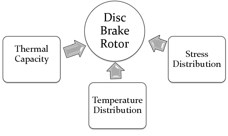
[image:19.612.126.527.318.557.2]To study thermal capacity, temperature distribution and stress distribution of the cross-drilled disc rotor for UTeM formula style car as show in figure 1.1 below.
Figure 1.1: Project Objective
Disc
Brake
Rotor
Thermal
Capacity
Distribution
Stress
3
1.3PROBLEM STATEMENT
Due to the main objective of this project it to help the UTeM Formula Varsity car achieve to the maximum performance and test the limitation of the braking system. In the previous design, the vehicle is heavy and low acceleration performance. The braking system is directly transferred from the motorcycle, therefore it is not fully adapt to the design of the formula style car. Furthermore, the design team does not understand the maximum tolerant limit of the braking component. In order the increase the performances of a race car, light weight is one of the effective ways.
i. To analyze the limitation of the rotor ii. Reduce the weight of unsprung body.
iii. Study the braking behavior of the rotor and find out the ways to reduce the weight base on the studied result.
1.4 SCOPE
i. To produce detail design of the component using 3D CAD Software. ii. To perform material selection for the component.
iii. To calculate the load acting on the component during operation.
4
CHAPTER 2
LITERATURE REVIEW
2.1 FORMULA VARSITY
2.1.1 History of the Formula Varsity
The initial concept of the formula varsity is based on the FSAE championship which is held in United State of America and Canada. Although size of the car is small, but purely a race machine. It can consider as “mini F1 “among university. The championship is challenging the engineering student in the aspect of design, build and compete with formula style racing machine. This competition has given chance for the University to prove them a better engineering college then other.
The concept behind Formula Varsity is that a fictional manufacturing company has contracted a design team to develop a small Formula-style race car. The prototype race car is to be evaluated for its potential as a production item. The target marketing group for the race car is the non-professional weekend autocross racer. Each student team designs, builds and tests a prototype based on a series of rules whose purpose is both to ensure onsite event operations and promote clever problem solving.
5
[image:22.612.189.467.171.382.2]Varsity takes students out of the classroom and allows them to apply textbook theories to real work experiences. (www.formulavasity.wordpress.com). The Figure 2.1 and Figure 2.2 show the photos obtain from UTeM Formula website.
Figure 2.1: Logo of Formula Varsity during 2006
[image:22.612.188.469.428.637.2]6
2.1.2. Design Rules
In the rules book of formula Varsity 2010, there are some basic rule and regulation for the brake system. There all listed in section 10.4.
i. Separate Circuits
All cars must have a brake system which has at least two separate circuits operated by the same pedal. This system must be designed so that if leakage or failure occurs in one circuit, the pedal shall still operate another brake.
ii. Brake Discs
Brake discs must be made from ferrous material. At least 2 discs must be attached to the rear wheel axle. iii. Brake Calipers
All brake calipers must be made from the homogeneous metallic Material.
Each disc may only be operated by one caliper, and each calliper must have no more than four pistons.
The use of steel-braided hose is permitted. iv. Brake Cooling
Brakes may only be cooled by air.
Liquid cooling of any part of the braking system is forbidden. v. Brake Pressure Modulation
7
[image:24.612.185.478.131.323.2]2.2 Disc Brake 2.2.1 Rotor Design
Figure: 2.3 Schematic diagrams for disc brake rotor (Boniardi., 2006)
Bridge is the section to support the flange area. The design of the bridge is simple as possible to decrease the weight of the rotor. Flange is the area where the frictions occur. The area of the flange is so called swept area where the mating area between the brake lining and the rotor.
The design of the disc varies somewhat. Some are simply solid cast iron, but others are hollowed out with fins or vanes joining together the disc's two contact surfaces (usually included as part of a casting process). This "ventilated" disc design helps to dissipate the generated heat and is commonly used on the more-heavily-loaded front discs. The front brakes provide most of the stopping power.