Cisco Press
800 East 96th Street
Indianapolis, IN 46240 USA
Cisco Press
Cisco Secure Firewall Services
Module (FWSM)
Cisco Secure Firewall Services Module (FWSM)
Ray Blair, Arvind DuraiCopyright© 2009 Cisco Systems, Inc. Published by:
Cisco Press 800 East 96th Street Indianapolis, IN 46240 USA
All rights reserved. No part of this book may be reproduced or transmitted in any form or by any means, electronic or mechanical, including photocopying, recording, or by any information storage and retrieval system, without writ-ten permission from the publisher, except for the inclusion of brief quotations in a review.
Printed in the United States of America First Printing September 2008
Library of Congress Cataloging-in-Publication Data: Blair, Ray,
Cisco secure firewall services module (FWSM) / Ray Blair, Arvind Durai. p. cm.
ISBN-13: 978-1-58705-353-5 (pbk.) ISBN-10: 1-58705-353-5 (pbk.)
1. Computer networks—Security measures. 2. Firewalls (Computer security) 3. Cisco Systems, Inc. I. Durai, Arvind. II. Title.
TK5105.59.B563 2009 005.8—dc22
2008030575
ISBN-13: 978-1-58705-353-5 ISBN-10: 1-58705-353-5
Warning and Disclaimer
This book is designed to provide information about the Firewall Services Module, using practical design examples. Every effort has been made to make this book as complete and as accurate as possible, but no warranty or fitness is implied.
The information is provided on an “as is” basis. The authors, Cisco Press, and Cisco Systems, Inc. shall have neither liability nor responsibility to any person or entity with respect to any loss or damages arising from the information contained in this book or from the use of the discs or programs that may accompany it.
The opinions expressed in this book belong to the author and are not necessarily those of Cisco Systems, Inc.
Trademark Acknowledgments
iii
Corporate and Government Sales
The publisher offers excellent discounts on this book when ordered in quantity for bulk purchases or special sales, which may include electronic versions and/or custom covers and content particular to your business, training goals, marketing focus, and branding interests. For more information, please contact:
U.S. Corporate and Government Sales 1-800-382-3419 [email protected] For sales outside the United States please contact:
International Sales [email protected]
Feedback Information
At Cisco Press, our goal is to create in-depth technical books of the highest quality and value. Each book is crafted with care and precision, undergoing rigorous development that involves the unique expertise of members from the professional technical community.
Readers’ feedback is a natural continuation of this process. If you have any comments regarding how we could improve the quality of this book, or otherwise alter it to better suit your needs, you can contact us through email at [email protected]. Please make sure to include the book title and ISBN in your message.
We greatly appreciate your assistance.
Publisher Paul Boger
Associate Publisher Dave Dusthimer
Cisco Representative Anthony Wolfenden
Cisco Press Program Manager Jeff Brady
Executive Editor Brett Bartow
Managing Editor Patrick Kanouse
Development Editor Dan Young
Senior Project Editor Tonya Simpson
Copy Editor Barbara Hacha
Technical Editors Sunil Gul Wadwani, Bryan Osoro
Editorial Assistant Vanessa Evans
Designer Louisa Adair
Composition Mark Shirar
Indexer John Bickelhaupt
Proofreader Kathy Ruiz
Cisco has more than 200 offices worldwide. Addresses, phone numbers, and fax numbers are listed on the Cisco Website at www.cisco.com/go/offices.
CCDE, CCENT, Cisco Eos, Cisco Lumin, Cisco Nexus, Cisco StadiumVision, the Cisco logo, DCE, and Welcome to the Human Network are trademarks.; Changing the Way We Work, Live, Play, and Learn is a service mark; and Access Registrar, Aironet, AsyncOS, Bringing the Meeting To You, Catalyst, CCDA, CCDP, CCIE, CCIP, CCNA, CCNP, CCSP, CCVP, Cisco, the Cisco Certified Internetwork Expert logo, Cisco IOS, Cisco Press, Cisco Systems, Cisco Systems Capital, the Cisco Systems logo, Cisco Unity, Collaboration Without Limitation, EtherFast, EtherSwitch, Event Center, Fast Step, Follow Me Browsing, FormShare, GigaDrive, HomeLink, Internet Quotient, IOS, iPhone, iQ Expertise, the iQ logo, iQ Net Readiness Scorecard, iQuick Study, IronPort, the IronPort logo, LightStream, Linksys, MediaTone, MeetingPlace, MGX, Networkers, Networking Academy, Network Registrar, PCNow, PIX, PowerPanels, ProConnect, ScriptShare, SenderBase, SMARTnet, Spectrum Expert, StackWise, The Fastest Way to Increase Your Internet Quotient, TransPath, WebEx, and the WebEx logo are registered trademarks of Cisco Systems, Inc. and/or its affiliates in the United States and certain other countries.
All other trademarks mentioned in this document or Website are the property of their respective owners. The use of the word partner does not imply a partnership relationship between Cisco and any other company. (0805R)
Americas Headquarters
Cisco Systems, Inc. San Jose, CA
Asia Pacific Headquarters
Cisco Systems (USA) Pte. Ltd. Singapore
Europe Headquarters
About the Authors
Ray Blairis a consulting systems architect and has been with Cisco Systems for more than eight years, working primarily on security and large network designs. He has 20 years of experience with designing, implementing, and maintaining networks that have included nearly all networking technologies. His first four years in the high-technology industry started with designing industrial computer systems for process monitoring. Mr. Blair maintains three Cisco Certified Internetwork Expert (CCIE) certifications in Routing and Switching, Security, and Service Provider. He also is a Certified Novell Engineer (CNE) and a Certified Information Systems Security Professional (CISSP).
Arvind Duraiis an advanced services technical leader for Cisco Systems. His primary responsibility has been in supporting major Cisco customers in the Enterprise sector, some of which includes Financial, Manufacturing, E-commerce, State Government, and Health Care sectors. One of his focuses has been on security, and he has authored several white papers and design guides in various technologies. Mr. Durai maintains two Cisco Certified Internetwork Expert (CCIE) certifications in Routing and Switching and Security. Mr. Durai holds a Bachelor of Science degree in Electronics and Communication, a Master’s degree in Electrical Engineering (MS), and Master’s degree in Business Administration (MBA).
About the Technical Reviewers
Sunil Wadwani, M.S, M.B.A, is a technical marketing engineer for the Security Technology Business Unit (STBU) at Cisco. Sunil is a 20-year veteran of the technology field with experiences in the design, development, and provisioning of networking products. His career in Cisco began in 1992, when he was part of a design team developing the first version of the Cisco 7200 router. Sunil’s primary responsibiliy today as a technical marketing engineer requires him to advise customers and sales engineeers on some of the deployment aspects of security products such as VPN, firewall, and IPS.
Sunil has an M.S in Computer Engineering from the University of California, Irvine, and an M.B.A from Santa Clara University. He lives in Saratoga, California with his wife Shalini and two sons, Shiv and Kunal.
v
Dedications
Ray Blair: As with everything in my life, I thank my Lord and Savior for his faithful leading that has brought me to this place. This book is dedicated to my wife, Sonya, and my children, Sam, Riley, Sophie, and Regan. You guys mean the world to me!
Arvind Durai: This book is dedicated to my wife, Monica, who pushed me in this endeavor, supported me during the long hours, and helped me achieve this goal—and to my son, Akhhill, who always gave me the extra energy that recharged me to work on this book.
To my parents, for providing me with values and opportunities.
To my brother and family, my parents-in-law, and brother-in-law and family for all their support and wishes.
Acknowledgments
Ray Blair:This project was a significant undertaking, and without the support of those mentioned below as well as many others, this would not have been an achievable goal. I am very grateful for all your help and support in completing this book!
To my nontechnical wife, who was the initial reviewer, who suffered through reading technical material, finding errors and phrasing that didn’t make sense, I will always remember your sacrifice and commit-ment to the success of this book—thank you!
Thanks to my children, Sam, Riley, Sophie, and Regan, for your patience in the many hours I spent working on this book and tolerating the “We’ll do it after I get this book done” response. Let’s go fishing!
Arvind, your excellent technical knowledge and the great working relationship that we have always enjoyed made writing this book a pleasure. I look forward to many more years as your colleague and friend.
Arvind Durai:
Thanks to my wife, who reviewed all my chapters several times during each stage of the book and gave me suggestions for improvement. She spent numerous late nights and early mornings working on the book review with me. I never felt alone. Thank you!
I would like to thank Andrew Maximow (director, Cisco Advanced Services), Uwe Fisher (manager, Advanced Services), and Naheed Alibhai (manager, Advanced Services) for supporting me in this effort. I also want to extend my thanks to all my peers with whom I worked on customer designs.
Ray, this book has been a great partnership. Your technical knowledge is awesome. You have been a great friend and colleague, and it is always a pleasure working with you.
Thanks to everyone who supported me directly or indirectly in every phase of the book. Without all your support, this book would not have been possible.
Our special thanks to:
We are very grateful to Bryan Osoro and Sunil Gul Wadwani. Without the talent of these two technical reviewers, the book wouldn’t have been possible.
A big thanks to the product, development, and test teams within Cisco that provided answers to ques-tions and prereleased code for testing: Reza Saada, Chandra Modumudi, Donovan Williams, Muninder Sambi, Munawar Hossain, Christopher Paggen, and Ben Basler.
The Cisco Press team was very helpful in providing excellent feedback and direction; many thanks to Brett Bartow, Christopher Cleveland, Dan Young, and Tonya Simpson.
vii
Contents at a Glance
Introduction xxi
Part I Introduction 3
Chapter 1 Types of Firewalls 5
Chapter 2 Overview of the Firewall Services Module 19
Chapter 3 Examining Modes of Operation 35
Chapter 4 Understanding Security Levels 53
Chapter 5 Understanding Contexts 73
Part II Initial Configuration 87
Chapter 6 Configuring and Securing the 6500/7600 Chassis 89
Chapter 7 Configuring the FWSM 105
Chapter 8 Access Control Lists 125
Chapter 9 Configuring Routing Protocols 135
Chapter 10 AAA Overview 171
Chapter 11 Modular Policy 183
Part III Advanced Configuration 195
Chapter 12 Understanding Failover in FWSM 197
Chapter 13 Understanding Application Protocol Inspection 219
Chapter 14 Filtering 235
Chapter 15 Managing and Monitoring the FWSM 245
Chapter 16 Multicast 265
Chapter 17 Asymmetric Routing 287
Chapter 18 Firewall Load Balancing 303
Chapter 19 IP Version 6 327
Chapter 20 Preventing Network Attacks 345
Part IV Design Guidelines and Configuration Examples 373
Chapter 22 Designing a Network Infrastructure 375
Chapter 23 Design Scenarios 401
Part V FWSM 4.x 447
Chapter 24 FWSM 4.x Performance and Scalability Improvements 449
Chapter 25 Understanding FWSM 4.x Routing and Feature Enhancements 469
ix
Contents
Introduction xxi
Part I Introduction 3
Chapter 1 Types of Firewalls 5
Understanding Packet-Filtering Firewalls 5
Advantages 5
Caveats 6
Understanding Application/Proxy Firewalls 7
Advantages 8
Caveats 8
Understanding Reverse-Proxy Firewalls 10 Advantages 10
Caveats 12
Utilizing Packet Inspection 12
Reusing IP Addresses 13
NAT 14
PAT 15
Summary 16
Chapter 2 Overview of the Firewall Services Module 19
Specifications 19
Installation 20
Performance 22
Virtualization 23
Comparing the FWSM to Other Security Devices 24
IOS FW 25
PIX 25
ASA 25
Hardware Architecture 26
Software Architecture 29
Chapter 3 Examining Modes of Operation 35
Working with Transparent Mode 35 Advantages 37
Disadvantages 40 Traffic Flow 40
Multiple Bridge Groups 45
Working with Routed Mode 46 Advantages 48
Disadvantages 48 Traffic Flow 48
Summary 51
References 51
Chapter 4 Understanding Security Levels 53
Traffic Flow Between Interfaces 54
Network Address Translation/Port Address Translation 55 Static NAT 58
Number of Simultaneous TCP Connections 61 Number of Embryonic Connections 61
DNS 62
Norandomseq 62
TCP 63
UDP 63
Static PAT 64
Dynamic NAT 67
Dynamic PAT 67
NAT Control 67
NAT Bypass 68
NAT 0 or Identity NAT 68 Static Identity NAT 68
Summary 70
References 70
Chapter 5 Understanding Contexts 73
Benefits of Multiple Contexts 74 Separating Security Policies 74
Leveraging the Hardware Investment 74
xi
Adding and Removing Contexts 75 Adding a Context 76
Removing a Context 77
Storing Configuration Files 77
Changing Between Contexts 78
Understanding Resource Management 79 Memory Partitions 80
Summary 85
Part II Initial Configuration 87
Chapter 6 Configuring and Securing the 6500/7600 Chassis 89
Understanding the Interaction Between the Host-Chassis and the FWSM 89
Assigning Interfaces 92
Securing the 6500/7600 (Host-Chassis) 94 Controlling Physical Access 95
Being Mindful of Environmental Considerations 95 Controlling Management Access 96
Disabling Unnecessary Services 97
Controlling Access Using Port-Based Security 99 Controlling Spanning Tree 99
Leveraging Access Control Lists 100 Securing Layer 3 100
Leveraging Control Plane Policing 101
Protecting a Network Using Quality of Service 101 Employing Additional Security Features 101
Summary 103
References 103
Chapter 7 Configuring the FWSM 105
Configuring FWSM in the Switch 105
Exploring Routed Mode 108
Exploring Transparent Mode 109
Using Multiple Context Mode for FWSM 111 Context Configurations 111
System Context Configurations 111 Admin Context Configurations 112
Configuration Steps for Firewall Services Module 113 Type 1: Configuring Single Context Routed Mode 114 Type 2: Configuring Single Context Transparent Mode 116 Type 3: Configuring Multiple Context Mixed Mode 119
Summary 123
Chapter 8 Access Control Lists 125
Introducing Types of Access Lists 125 Understanding Access Control Entry 127 Understanding Access List Commit 128
Understanding Object Groups 128
Monitoring Access List Resources 129
Configuring Object Groups and Access Lists 129 Working with Protocol Type 129
Working with Network Type 130 Working with Service Type 130 Working with Nesting Type 130 Working with EtherType 131
Summary 132
Chapter 9 Configuring Routing Protocols 135
Supporting Routing Methods 136 Static Routes 136
Default Routes 137
Open Shortest Path First 137 SPF Algorithm 137
OSPF Network Types 138
Concept of Areas 139
OSPF Link State Advertisement 140 Types of Stub Area in OSPF 141
OSPF in FWSM 141
OSPF Configuration in FWSM 142
Interface-Based Configuration for OSPF Parameters 142 Summarization 143
Stub Configuration 143 NSSA Configuration 144 Default Route Information 144
Timers 144
xiii
OSPF Design Example 2 149 Routing Information Protocol 154
RIP in FWSM 154
Configuration Example of RIP on FWSM 154 Border Gateway Protocol 158
BGP in FWSM 159
BGP Topology with FWSM 159
Summary 169
Chapter 10 AAA Overview 171
Understanding AAA Components 171 Authentication in FWSM 171 Authorization in FWSM 172
Accounting in FWSM 172
Comparing Security Protocols 173
Understanding Two-Step Authentication 175
Understanding Fallback Support 175 Configuring Fallback Authentication 175 Configuring Local Authorization 177
Understanding Cut-Through Proxy in FWSM 178 Configuring Custom Login Prompts 180
Using MAC Addresses to Exempt Traffic from Authentication and Authorization 181
Summary 181
Chapter 11 Modular Policy 183
Using Modular Policy in FWSM 183
Understanding Classification of Traffic 185 Understanding Application Engines 187
Defining Policy Maps 189 Configuring Global Policy 189
Configuring Service Policy 190
Understanding Default Policy Map 190
Sample Configuration of Modular Policy in FWSM 191
Part III Advanced Configuration 195
Chapter 12 Understanding Failover in FWSM 197
Creating Redundancy in the FWSM 197 Understanding Active/Standby Mode 197 Understanding Active/Active Mode 198
Understanding Failover Link and State Link 199
Requirements for Failover 201
Synchronizing the Primary and Secondary Firewalls 201
Monitoring Interfaces 202
Configuring Poll Intervals 203
Design Principle for Monitoring Interfaces 203
Configuring Single Context FWSM Failover 205
Configuring Multiple Context FWSM Failover 212
Summary 217
Chapter 13 Understanding Application Protocol Inspection 219
Inspecting Hypertext Transfer Protocol 220
Inspecting File Transfer Protocol 222
Working with Supported Applications 224
Configuring ARP 229 Inspecting ARP 230
Configuring Parameters for ARP 231 Configuring MAC Entries 231 Adding Static Entries 231
Summary 233
References 233
Chapter 14 Filtering 235
Working with URLs and FTP 235
Configuring ActiveX and Java 241
Summary 242
xv
Chapter 15 Managing and Monitoring the FWSM 245
Using Telnet 245
Using Secure Shell 247
Using Adaptive Security Device Manager 249
Configuring the FWSM Using ASDM 249
Managing the FWSM from the Client 249
Securing Access 251
Configuring the FWSM for VPN Termination 252 Configuring the VPN Client 254
Working with Simple Network Management Protocol 257
Examining Syslog 258
Working with Cisco Security Manager 260
Monitoring Analysis and Response System 262
Summary 263
References 263
Chapter 16 Multicast 265
Protocol Independent Multicast 265
Understanding Rendezvous Point 267
PIM Interface Modes 268
IGMP Protocol 268
Multicast Stub Configuration 269
Multicast Traffic Across Firewalls 269 FWSM 1.x and 2.x Code Releases 269 FWSM 3.x Code Release 270
Configuration Methods 273
Method 1: Configuration Example for Multicast Through Firewall in Single Context Routed Mode 273
Method 2: Configuration Example for Multicast Through Firewall via GRE 276 Method 3: Configuration Example for Multicast Through Transparent Firewall in
Multiple Context Mode 279
Chapter 17 Asymmetric Routing 287
Asymmetric Routing Without a Firewall 287
Asymmetric Traffic Flow in a Firewall Environment 289
Avoiding Asymmetric Routing Through Firewalls 290 Option 1: Symmetric Routing Through Firewalls 290
Option 2: Firewall Redundancy and Routing Redundancy Symmetry 292
Supporting Asymmetric Routing in FWSM 294
Asymmetric Routing Support in Active/Standby Mode 294 Asymmetric Routing Support in Active/Active Mode 295
Configuring ASR in FWSM 297
Summary 301
Chapter 18 Firewall Load Balancing 303
Reasons for Load Balancing Firewalls 303
Design Requirements for Firewall Load Balancing 304
Firewall Load-Balancing Solutions 305
Firewall Load Balancing with Policy-Based Routing 305 Firewall Load Balancing with Content Switch Module 307
Configuring the CSM 308
Snapshot Configuration for CSM Supporting Firewall Load Balancing 311 Firewall Load Balancing Using the Application Control Engine 313
ACE Design for Firewall Load Balancing 313
Firewall Load Balancing Configuration Example 318 OUT2IN Policy Configuration 319
Firewall Configuration 319 IN2OUT Policy Configuration 323
Summary 324
Chapter 19 IP Version 6 327
Understanding IPv6 Packet Header 327
Examining IPv6 Address Types 329 Neighbor Discovery Protocol 329
IPv6 in FWSM 330
Configuring Multiple Features of IPv6 in FWSM 331 Interface Configuration 331
xvii
Duplicate Address Detection 333
Timer for Duplicate Address Detection 333 Configuring Access Lists 334
Configuring Static Routes 334
Configuring IPv6 Timers in FWSM 334 Configuring IPv6 in FWSM 335
Configuring PFC (Layer 3 Device) on the Outside Security Domain 336
Configuring FWSM 337
Configuring a Layer 3 Device on the Inside Security Domain 338 Verify the Functionality of FWSM 339
Working with the show Command for IPv6 in FWSM 340
Summary 343
Chapter 20 Preventing Network Attacks 345
Protecting Networks 345
Shunning Attackers 347
Spoofing 349
Understanding Connection Limits and Timeouts 350 Configuring Connection Limits 351
Configuring Timeouts 352
Summary 354
References 354
Chapter 21 Troubleshooting the FWSM 357
Understanding Troubleshooting Logic 357
Assessing Issues Logically 357
Connectivity Test of a Flow at the FWSM 360 Troubleshooting Flow Issues 360
FAQs for Troubleshooting 363
How Do You Verify Whether the Traffic Is Forwarded to a Particular Interface in
the FWSM? 363
How Do I Verify ACL Resource Limits? 364
How Do I Verify the Connectivity and Packet Flow Through the Firewall? 365 What Is Network Analysis Module? 365
What Are Some Useful Management and Monitoring Tools? 368 How Do I Recover Passwords? 369
Part IV Design Guidelines and Configuration Examples 373
Chapter 22 Designing a Network Infrastructure 375
Determining Design Considerations 375 Documenting the Process 376
Determining Deployment Options 377
Determining Placement 378
Working with FWSM and the Enterprise Perimeter 382 FWSM in the Datacenter 383
Throughput 383
Flexibility 383 Availability 384
Supporting Virtualized Networks 384
Summary 399
Reference 399
Chapter 23 Design Scenarios 401
Layer 3 VPN (VRF) Terminations at FWSM 401 Configuring the PFC 405
Configuring the FWSM 406
Failover Configuration in Mixed Mode 408
Interdomain Communication of Different Security Zones Through a Single
FWSM 415
Configuring the PFC 416
FWSM Configuration 418
Dynamic Learning of Routes with FWSM 424 Single Box Solution with OSPF 425
Data Center Environment with the FWSM 430
Method 1: Layer 3 VPN Segregation with Layer 3 FWSM (Multiple Context
Mode) 430
Method 2: Layer 3 VPN Segregation with Layer 2 FWSM (Multiple Context
Mode) 432
PVLAN and FWSM 434
PVLAN Configuration in FWSM 435
Design Scenario 1 for PVLAN in FWSM 435 Design Scenario 2 for PVLAN in FWSM 436
Configuring PVLAN 438
xix
Part V FWSM 4.x 447
Chapter 24 FWSM 4.x Performance and Scalability Improvements 449
Increasing Performance by Leveraging the Supervisor 449
Using the PISA for Enhanced Traffic Detection 453
Improving Memory 458
Partitioning Memory 459 Reallocating Rules 461
Optimizing ACL 464
Summary 466
Chapter 25 Understanding FWSM 4.x Routing and Feature Enhancements 469
Configuring EIGRP 469
Configuring Route Health Injection 473
Understanding Application Support 477 Configuring Regular Expressions 477
Understanding Application Inspection Improvements 481
Additional Support for Simple Network Management Protocol Management Information Base 482
Miscellaneous Security Features 484
Dynamic Host Configuration Protocol Option 82 484 Smartfilter HTTPS Support 485
Summary 485
References 485
Icons Used in This Book
Command Syntax Conventions
The conventions used to present command syntax in this book are the same conventions used in the IOS Command Reference. The Command Reference describes these conventions as follows:
• Boldfaceindicates commands and keywords that are entered literally as shown. In actual con-figuration examples and output (not general command syntax), boldface indicates commands that are manually input by the user (such as a show command).
• Italic indicates arguments for which you supply actual values. • Vertical bars (|) separate alternative, mutually exclusive elements. • Square brackets ([ ]) indicate an optional element.
• Braces ({ }) indicate a required choice.
• Braces within brackets ([{ }]) indicate a required choice within an optional element. PC
Web Server
Laptop
Router Switch Bridge
Server
Ethernet Connection
Serial Line Connection
Firewall Services Module
Firewall PIXFirewall
Route Switch Processor
Multi-Switch Device
Router with Firewall
xxi
Introduction
Firewalls are one of the main components used in securing a network infrastructure, and having an in-depth understanding of how these devices function is paramount to maintaining a secure network. This book was written to provide an understanding of the functionality of the Firewall Services Module (FWSM), from both a hardware and software perspective and to be a practical design guide with config-uration examples for the design, implementation, operation, and management of FWSM in various deployment scenarios.
Who Should Read This Book?
This book is targeted at individuals who would like an in-depth understanding of the FWSM. It is focused primarily for those who design, implement, or maintain the FWSM, such as security/network administrators. To get the most value from the material, the reader should have at least an intermediate knowledge of networking and security.
How This Book Is Organized
This book is organized into five sections that cover the basic introduction of firewalls, initial and advanced configurations, design guides and configuration examples, and features and functionality introduced in FWSM version 4.x code:
• Chapter 1, “Types of Firewalls”: This chapter explains the functionality of the different types of firewalls.
• Chapter 2, “Overview of the Firewall Services Module”: This chapter covers specifications, installation information, performance, and virtualization; shows a comparison of IOS FW, ASA, and FWSM; and also explains the hardware and software architecture.
• Chapter 3, “Examining Modes of Operation”:This chapter examines the modes of opera-tion (transparent/routed) and explains the advantages of each.
• Chapter 4, “Understanding Security Levels”:This chapter explains how traffic flows between interfaces, using both NAT and PAT and routed and transparent modes.
• Chapter 5, “Understanding Contexts”:This chapter provides an overview of the benefits of contexts and how to manage them.
• Chapter 6, “Configuring and Securing the 6500/7600 Chassis”:This chapter explains how to configure the host chassis to support the FWSM.
• Chapter 7, “Configuring the FWSM”:This chapter covers the initial configuration of the FWSM.
• Chapter 8, “Access Control Lists”:This chapter examines the use of ACLs.
• Chapter 10, “AAA Overview”:This chapter covers the principles of using authentication, authorization, and accounting.
• Chapter 11, “Modular Policy”:This chapter covers the use of class and policy maps. • Chapter 12, “Understanding Failover in FWSM”:This chapter explains the use and
config-uration of using multiple FWSMs for high availability.
• Chapter 13, “Understanding Application Protocol Inspection”:This chapter covers the use and configuration of application and protocol inspection.
• Chapter 14, “Filtering”:This chapter examines how traffic can be filtered using filter servers and how Active X and Java filtering function.
• Chapter 15, “Managing and Monitoring the FWSM”:This chapter covers the different options of managing and monitoring the FWSM.
• Chapter 16, “Multicast”:This chapter explains the interaction of multicast with the FWSM and provides some practical examples.
• Chapter 17, “Asymmetric Routing”:This chapter provides an explanation of asymmetric routing and how it can be configured.
• Chapter 18, “Firewall Load Balancing”:This chapter covers the options of how to increase performance using multiple FWSMs.
• Chapter 19, “IP Version 6”:This chapter explains IPv6 and how it is configured on the FWSM.
• Chapter 20, “Preventing Network Attacks”:This chapter examines how to mitigate network attacks, using shunning, antispoofing, connection limits, and timeouts.
• Chapter 21, “Troubleshooting the FWSM”:This chapter explains how to leverage the appropriate tools to solve problems.
• Chapter 22, “Designing a Network Infrastructure”:This chapter covers an overview on placement of the FWSM in the network.
• Chapter 23, “Design Scenarios”:This chapter provides many practical examples of how the FWSM can be configured.
• Chapter 24, “FWSM 4.x Performance and Scalability Improvements”: This chapter covers the performance improvements in 4.x code.
P
A R T
I
Introduction
Chapter 1 Types of Firewalls
Chapter 2 Overview of the Firewall Services Module
Chapter 3 Examining Modes of Operation
Chapter 4 Understanding Security Levels
C
H A P T E R
1
Types of Firewalls
By definition, a firewall is a single device used to enforce security policies within a network or between networks by controlling traffic flows.
The Firewall Services Module (FWSM) is a very capable device that can be used to enforce those security policies. The FWSM was developed as a module or blade that resides in either a Catalyst 6500 series chassis or a 7600 series router chassis. The “tight” integration with a chassis offers increased flexibility, especially with network virtualization and the incredible throughput that is not only available today but will increase significantly with the introduction of the 4.x code train.
The look and feel of the FWSM is similar to that of the PIX and ASA. These products are all part of the same family, originating with the PIX and the “finesse” operating system. If you have had any experience with either the PIX or ASA, you will find comfort in not having to learn another user interface.
Having a good understanding of the capabilities offered by the different types of firewalls will help you in placing the appropriate type of firewall to best meet your security needs.
Understanding Packet-Filtering Firewalls
Packet-filtering firewalls validate packets based on protocol, source and/or destination IP addresses, source and/or destination port numbers, time range, Differentiate Services Code Point (DSCP), type of service (ToS), and various other parameters within the IP header. Packet filtering is generally accomplished using Access Control Lists (ACL) on routers or switches and are normally very fast, especially when performed in an Application Specific Integrated Circuit (ASIC). As traffic enters or exits an interface, ACLs are used to match selected criteria and either permit or deny individual packets.
Advantages
Routers from the very smallest home office to the largest service-provider devices inherently have the capability to control the flow of packets through the use of ACLs.
Switches may use Routed Access-Control Lists (RACLs), which provide the capability to control traffic flow on a “routed” (Layer 3) interface; Port Access Control Lists (PACL), which are assigned to a “switched” (Layer 2) interface; and VLAN Access Control Lists (VACLs), which have the capability to control “switched” and/or “routed” packets on a VLAN.
Other networking devices may also have the power to enforce traffic flow through the use of ACLs. Consult the appropriate device documentation for details.
Packet-filtering firewalls are most likely a part of your existing network. These devices may not be the most feature rich, but when you need to quickly implement a security policy to mitigate an attack, protect against infected devices, and so on, this may be the quickest solution to deploy.
Caveats
The challenge with packet-filtering firewalls is that ACLs are static, and packet filtering has no visibility into the data portion of the IP packet.
TIP Packet-filtering firewalls do not have visibility into the payload.
Because packet-filtering firewalls match only individual packets, this enables an individual with malicious intent, also known as a “hacker,” “cracker,” or “script kiddie,” to easily circumvent your security (at least this device) by crafting packets, misrepresenting traffic using well-known port numbers, or tunneling traffic unsuspectingly within traffic allowed by the ACL rules. Developers of peer-to-peer sharing applications quickly learned that using TCP port 80 (www) would allow them unobstructed access through the firewall.
NOTE The terms used to describe someone with malicious intent may not be the same in all circles.
• A cracker refers to someone who “cracks” or breaks into a network or computer, but can also define someone who “cracks” or circumvents software protection methods, such as keys. Generally it is not a term of endearment.
Understanding Application/Proxy Firewalls 7
• A script kiddie is someone who uses the code, methods, or programs created by a hacker for malicious intent.
Figure 1-1 shows an example of a packet-filtering firewall, a router using a traditional ACL in this case, access-list 100. Because the ACL is matching traffic destined for port 80, any flows destined to port 80, no matter what kind, will be allowed to pass through the router.
Figure 1-1 Packet-Filtering Firewall
Given the issues with packet filtering and the fact that they’re easy to circumvent, you may dismiss using them entirely. This would be a huge mistake! Taking a holistic approach and using multiple devices to provide defense in depth is a much better strategy. An excellent use of packet filtering is on the border of your network, preventing spoofed traffic and private IP addresses (RFC 1918) from entering or exiting your network. In-depth ACL configuration is beyond the scope of this book, but a good reference is RFC 2827.
Understanding Application/Proxy Firewalls
The following section uses the Open System Interconnection (OSI) model in the description of application/proxy firewalls and warrants a brief review. The OSI model describes how information is transmitted from an application on one computer to an application on another. Each layer performs a specific task on the information and passes it to the next layer. This model helps explain where functions take place.
The seven layers of the OSI model are as follows:
•
Layer 7 is the application layer: It is the user interface to your computer (the programs), for example, word processor, e-mail application, telnet, and so on.•
Layer 6 is the presentation layer: It acts as the translator between systems, converting application layer information to a common format understandable by different systems. This layer handles encryption and standards such as Motion Picture Experts Group (MPEG) and Tagged Image File Format (TIFF).Inside Outside
Incoming ACL
access-list 100 permit tcp any eq www any
Packet-Filter
Peer-to-Peer Client Peer-to-Peer Client
•
Layer 5 is the session layer: It manages the connections or service requests between computers.•
Layer 4 is the transport layer: It prepares data for delivery to the network. Transmission Control Protocol is a function of Layer 4, providing reliablecommunication and ordering of data. User Datagram Protocol is also a role of Layer 4, but it does not provide reliable delivery of data.
•
Layer 3 is the network layer: It is where IP addressing and routing happen. Data at this layer is considered a “packet.”•
Layer 2 is the data-link layer: It handles the reliable sending of information. Media Access Control is a component of Layer 2. Data at this layer would be referred to as a “frame.”•
Layer 1 is the physical layer: It is composed of the objects that you can see and some that you cannot, such as electrical characteristics.TIP Use the following mnemonic to remember the OSI model: All People Seem To Need Data Processing.
Application firewalls, as indicated by the name, work at Layer 7, or the application layer of the OSI model. These devices act on behalf of a client (aka proxy) for requested services. For example, open a web browser and then pen a web page to www.cisco.com. The request is sent to the proxy firewall, and then the proxy firewall acting on your behalf opens a web connection to www.cisco.com. That information is then transmitted to your web browser for your viewing pleasure.
Advantages
Because application/proxy firewalls act on behalf of a client, they provide an additional “buffer” from port scans, application attacks, and so on. For example, if an attacker found a vulnerability in an application, the attacker would have to compromise the application/ proxy firewall before attacking devices behind the firewall. The application/proxy firewall can also be patched quickly in the event that a vulnerability is discovered. The same may not hold true for patching all the internal devices.
Caveats
Understanding Application/Proxy Firewalls 9
able to support it without making some significant modifications. Second, application firewalls are generally much slower than packet-filtering or packet-inspection firewalls because they have to run applications, maintain state for both the client and server, and also perform inspection of traffic.
Figure 1-2 shows an application/proxy firewall and how a session is established through it to a web server on the outside.
Figure 1-2 Application/Proxy Firewall
The step-by-step process, as shown in the figure, is as follows:
Step 1 The client attempts to connect to the web server located on the outside. For example, a user enters www.cisco.com in a web browser.
Step 2 The proxy server receives the request and forwards that request to the appropriate web server (www.cisco.com).
Step 3 The web server receives the request and responds back to the proxy server with the requested information.
Step 4 The proxy server receives the information and forwards it to the originating client.
NOTE For simplicity’s sake, Domain Name Service (DNS), Address Resolution Protocol (ARP), and Layer 2/3 information is not discussed in this example. This also assumes that the client web application has been configured with the appropriate proxy information.
Application/proxy firewalls can be very effective devices to control traffic flow and protect clients from malicious software (malware) and outside attacks. These firewalls must also run applications similar to the clients, which can also make them vulnerable to application attacks.
Inside Outside
1. Client requests web page from proxy. 2. Proxy requests web page from web server.
4. Proxy returns information to client. 3. Web server returns information to proxy.
Client Proxy Web Server
Understanding Reverse-Proxy Firewalls
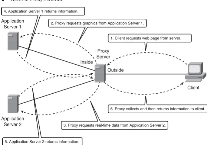
Reverse-proxy firewalls function in the same way as proxy firewalls, with the exception that they are used to protect the servers and not the clients. Clients connecting to a web server may unknowingly be sent to a proxy server, where it services the request on behalf of the client. The proxy server may also be able to load balance the requests to multiple servers, consequently spreading the workload.
Advantages
To be really effective, reverse proxies must understand how the application behaves. For example, suppose you have a web application that requires input of a mailing address, specifically the area code. The application firewall needs to be intelligent enough to deny information that could cause the server on the far end any potential issues, such as a buffer overflow.
NOTE A buffer overflow occurs when the limits of a given allocated space of memory is exceeded. This results in adjacent memory space being overwritten. If the memory space is
overwritten with malicious code, it can potentially be executed, compromising the device.
If a cracker were to input letters or a long string of characters into the ZIP code field, this could cause the application to crash. As we all know, well-written applications “shouldn’t” allow this type of behavior, but “carbon-based” mistakes do happen, and having defense in depth helps minimize the human element. Having the proxy keenly aware of the application and what’s allowed is a very tedious process. When any changes are made to the
application, the proxy must also change. Most organizations deploying reverse-proxy firewalls don’t usually couple their proxy and applications so tightly to get the most advantage from them, but they should.
Understanding Reverse-Proxy Firewalls 11
Figure 1-3 Reverse-Proxy Firewall
The step-by-step process, as shown in the figure, is as follows:
Step 1 The client opens a web browser and enters the URL that directs them to the associated proxy web server, requesting information.
Steps 2 and 3 The proxy server can have multiple locations from which to glean information, in this example, it requests graphics from Application Server 1 and real-time data from Application Server 2.
Steps 4 and 5 The proxy server prepares the content received from Application Servers 1 and 2 for distribution to the requesting client.
Step 6 The proxy server responds to the client with the requested information.
As you can see by the previous example, the function of a reverse-proxy server is very beneficial in distributing the processing function over multiple devices and by providing an additional layer of security between the client requesting information and the devices that contain the “real” data.
Inside
Outside
1. Client requests web page from server. 4. Application Server 1 returns information.
2. Proxy requests graphics from Application Server 1.
6. Proxy collects and then returns information to client.
5. Application Server 2 returns information.
3. Proxy requests real-time data from Application Server 2.
Client Application
Server 1
Application Server 2
Caveats
The same caveats that apply to proxy firewalls also apply to reverse-proxy firewalls, but with a much higher degree of visibility. Because reverse-proxy firewalls are generally providing a service to customers outside the organization, when access to these services is lost so is revenue in the form of access to critical information, such as patient data or product information. With that consideration, it’s even more imperative to keep these services running.
Reverse-proxy firewalls aid in protecting and load balancing servers; they also provide a barrier between clients and critical applications through proxy services. Well-written proxy servers significantly reduce the risk of a security breach.
Utilizing Packet Inspection
Packet-inspection firewalls look at the session information between devices. Session information is typically protocol, new or existing connection, source and destination IP address and port numbers, IP checksum, sequence numbers, and application-specific information, such as command and response conditions in Simple Mail Transfer Protocol (SMTP).
A typical flow of traffic from client to server starts with a client initiating the connection to the IP address of the web server destined for port 80 (HTTP). The packet-inspection firewall determines whether that packet is allowed through the firewall based on the current rule-set. If the firewall has the capability to look into the data portion of the IP packet and determine whether it is legitimate Hypertext Transfer Protocol (HTTP) traffic, this process is considered a “deep-packet” inspection because it validates the payload. If all the requirements are met, a flow entry is created in the firewall based on the session
information, and that packet is allowed to pass through the firewall. The web server receives the packet and responds accordingly. Return traffic is received by the outside interface of the firewall. The firewall determines whether the return traffic is allowed by comparing the session information (source and destination IP, port numbers, sequence numbers, and so on) with the information contained in the local translation table. If the return traffic matches the previous requirements, the IP payload can be inspected to validate appropriate HTTP compliance (deep-packet inspection), and then it is forwarded to the client.
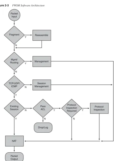
Reusing IP Addresses 13
Figure 1-4 Packet-Inspection Flow Diagram
Packet-inspection firewalls are generally much faster than application firewalls because they are not required to host client applications. Most of the packet-inspection firewalls today also offer very good application or deep-packet inspection. This process allows the firewall to dig into the data portion of the packet and match on protocol compliance, scan for viruses, and so on and still operate very quickly.
Reusing IP Addresses
A feature that is common among all firewalls is Network Address Translation (NAT) and Port Address Translation (PAT) . NAT obfuscates the IP address scheme you are using internally, and the PAT function helps minimize the use of public address space.
Figure 1-5 shows how a firewall can be used to provide NAT and/or PAT functionality.
Figure 1-5 IP Address Reuse
Inside Outside
3. Forward packet. 2. Add a session entry.
1. Does the firewall rule-set allow this packet? YES.
5. Forward packet. 4. Is this packet part of an existing session? YES.
Client Web Server
Packet-Inspection
Firewall
Inside Outside
Is the return traffic legitimate?
IP address, port number, HTTP, and so on. Is the outgoing session allowed? Should the traffic use NAT or PAT functionality?
Client Packet- Web Server
NAT
NAT provides the capability to change the source and/or destination IP address. This is common when private address space is used internally. NAT has a one-to-one relationship between inside and outside IP addresses.
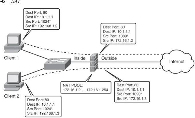
Figure 1-6 shows two clients located on the inside of the firewall. Client 1 has an IP address of 192.168.1.2 and Client 2 has an IP address of 192.168.1.3. A NAT pool of addresses has been assigned to the firewall using IP addresses 172.16.1.2 through 172.16.1.254.
When Client 1 attempts to connect to the Internet, the firewall has been configured to take an IP address from the pool and change the client’s source address to the address from the pool. Notice that when the connection passes through the firewall, the source address changed from 192.168.1.2 to 172.16.1.2 (the first address in the pool).
When Client 2 establishes a connection through the firewall, it will get the second address from the pool. As you can see, the size of the pool is directly proportional to the number of clients allowed through. When the 255th client attempts to make a connection through the firewall, the pool of addresses will have been completely allocated and the connection will be denied. This problem will be addressed in the next section, “PAT.”
[image:37.526.90.430.363.568.2]NAT functionality can also be configured statically, called “static” NAT (can you believe it). This feature permanently maps inside to outside or outside to inside addresses. This allows connections from the outside to be established to the inside, using a mapped IP address.
Figure 1-6 NAT
Inside Outside
NAT POOL:
172.16.1.2 — 172.16.1.254 Dest Port: 80 Dest IP: 10.1.1.1 Src Port: 1089* Src IP: 172.16.1.2 Dest Port: 80
Dest IP: 10.1.1.1 Src Port: 1024* Src IP: 192.168.1.2
Dest Port: 80 Dest IP: 10.1.1.1 Src Port: 1090* Src IP: 172.16.1.3 Dest Port: 80
Dest IP: 10.1.1.1 Src Port: 1024* Src IP: 192.168.1.3 Client 1
Client 2
Internet
* Indicates an ephemeral port, which is a temporary port not currently in use. For Windows the ports are 1024 to 4999.
Reusing IP Addresses 15
The use of shared NAT pools conserves valuable public IP address space and also supports applications that aren’t very well behaved and opens random ports for communication. Static NAT will not conserve public IP addresses, but it provides a mechanism for clients on the public network (Internet) to access services that are privately addressed.
PAT
PAT, on the other hand, has a one-to-many IP address relationship. A common
implementation is using a private address space internally but having only one public IP address; this could be the case on your home network. Translations are performed at the transport layer of the OSI model.
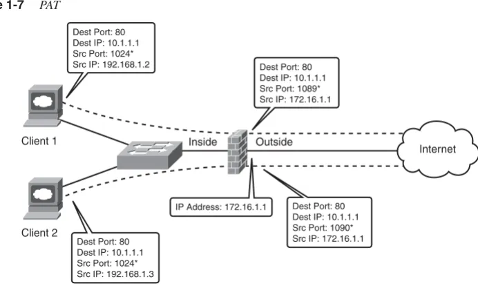
Figure 1-7 is similar to Figure 1-6, except that instead of a pool of addresses on the firewall, the firewall has been configured to translate the client addresses to the outside IP address of the firewall.
When Client 1 connects through the firewall, the firewall changes the source address of 192.168.1.2 to 172.16.1.1.
When Client 2 connects through the firewall, the firewall changes the source address from 192.168.1.3 to 172.16.1.1.
Figure 1-7 PAT
As you can see, PAT gives you much better scalability from an IP usage standpoint, consequently reducing the number of public IP addresses required on the Internet. You will also see in Chapter 4, “Understanding Security Levels,” how PAT can be used by clients to access multiple resources using the same IP address.
Summary
Three basic types of firewalls —packet filtering, application, and packet inspection—are designed to control traffic flows. The previous descriptions provide general functionality of the operation of these types of firewalls. Individual vendors may employ additional features; you should refer to their documentation for specific information.
You might be wondering where the FWSM fits. The FWSM is a packet-inspection firewall with many more bells and whistles that will be explained in the following chapters.
Inside Outside
IP Address: 172.16.1.1 Dest Port: 80 Dest IP: 10.1.1.1 Src Port: 1089* Src IP: 172.16.1.1 Dest Port: 80
Dest IP: 10.1.1.1 Src Port: 1024* Src IP: 192.168.1.2
Dest Port: 80 Dest IP: 10.1.1.1 Src Port: 1090* Src IP: 172.16.1.1 Dest Port: 80
Dest IP: 10.1.1.1 Src Port: 1024* Src IP: 192.168.1.3 Client 1
Client 2
Internet
C
H A P T E R
2
Overview of the
Firewall Services Module
The Firewall Services Module (FWSM) is a very sophisticated combination of hardware and software. The better understanding you have of the attributes and architecture, the better your ability to design, deploy, manage, and troubleshoot a security infrastructure.
Specifications
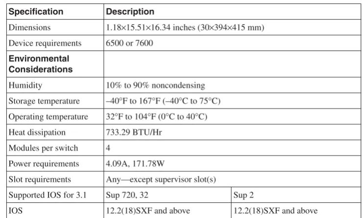
[image:42.526.104.474.384.607.2]The FWSM is a single line-card/module that can be installed in either a 6500 series switch or 7600 series router (one to four modules are supported in a single 6500 or 7600 chassis— assuming slots are available). Dynamic routing is also supported through Routing Information Protocol (RIP), Open Shortest Path First (OSPF), or Border Gateway Protocol (BGP) stub in single-context mode. Enhanced Interior Gateway Routing Protocol (EIGRP) will also be supported in the 4.x code train. Table 2-1 and Table 2-2 provide additional requirements and specifications.
Table 2-1 General Requirements
Specification Description
Dimensions 1.18×15.51×16.34 inches (30×394×415 mm) Device requirements 6500 or 7600
Environmental Considerations
Humidity 10% to 90% noncondensing
Storage temperature –40°F to 167°F (–40°C to 75°C) Operating temperature 32°F to 104°F (0°C to 40°C) Heat dissipation 733.29 BTU/Hr
Modules per switch 4
Power requirements 4.09A, 171.78W
Slot requirements Any—except supervisor slot(s)
Supported IOS for 3.1 Sup 720, 32 Sup 2
IOS 12.2(18)SXF and above 12.2(18)SXF and above
As you can clearly see from the specification in the previous two tables, good things do come in small packages!
Installation
Before you begin the installation of the FWSM, you should not only have a Phillips screwdriver and an antistatic strap, but if you are putting it in a production device, you should have a plan. Take into consideration the additional power required for the FWSM, which slot it should be placed in, whether the FWSM has a configuration that may cause a network outage, and so on.
Because the FWSM doesn’t have external connections, consider placing it between modules that have many physical connections to provide an additional space to route cables. Also, if you ever plan to use a redundant supervisor, avoid slots that would be used for the redundant supervisor, if possible.
Specification Description
IOS Modularity 12.2(18)SXF4 and above Not supported
Catalyst OS 8.5(3) and above 8.5(3) and above
Weight Minimum: 3 lb (1.36 kg)
Maximum: 5 lb (2.27 kg)
Table 2-2 General Specifications
Specification Description
Backplane connection 6G/s with fabric module 32G/s with shared bus Licensed features Contexts 20, 50, 100, and 250
GTP/GPRS
Jumbo support 8500B packet
Memory 1GB RAM
128MB Flash
[image:43.526.58.473.79.354.2]Security contexts 3
Installation 21
WARNING Only qualified individuals should install or remove an FWSM. Serious injury or death could occur. Whenever you are working with AC or DC power, safety is always a concern. Always use an appropriately connected grounding mechanism, such as a wrist strap, to prevent electrostatic discharge (ESD), and touch only the bottom edge of the module. If ESD precautions are not employed, you could damage circuitry, which may not be apparent immediately.
To install FWSM, follow these steps:
Step 1 Select a vacant slot.
Step 2 Remove the existing filler-plate by taking out the two Phillips screws.
Step 3 Open the ejector levers on the FWSM.
Step 4 Align the slides on the FWSM with the slot guides on both sides (top and bottom for Network Equipment Building Systems [NEBS]) of the chassis. That’s shiny side down or left for NEBS.
Step 5 Insert the FWSM into the chassis until the ejector levers begin to close.
Step 6 Close both ejector levers simultaneously until they are flush with the front of the FWSM.
Step 7 Tighten both captive screws on the FWSM.
The FWSM supports hot swapping, which allows you to install or remove the module while the chassis is powered. To reduce injury and minimize any potential damage, it’s always best to power down the chassis before installing or removing the module.
In addition, when removing the FWSM from the chassis, either depress the Shutdown button on the FWSM or issue the following command on the host chassis to gracefully shut down the FWSM:
Host-chassis# hhhhwwww--m--mommodooddduuuullllee ee mmmmoodooddduuluulelleee <<<<ssssllollooott-tt---nnunnuuummmmbbebbeeerr>rr>>> sssshhhhuutuutdttdoddooowwwwnnnn
Verify that the status LED on the FWSM is either orange or off before removing the module.
Performance
The FWSM has both application and protocol inspection engines for stateful inspection of traffic and can handle up to 1,000,000 connections at a connection rate of 100,000 per second. A single FWSM supports more than 5 gigabits (Gbs) of throughput and more than 20 Gbs with four modules in a chassis. The FWSM supports 250 virtual contexts, which are unique firewall instances that can be in either a routed mode, transparent mode, or a combination of each. Table 2-3 and Table 2-4 show many of the capabilities and limitations of the FWSM.
Table 2-3 Single/Multiple Context Mode.
Specification Single Multiple
Authentication, Authorization, and Accounting (AAA) connection rate
80/sec 80/second shared
Access Control List (ACL) flow logging 32K 32K shared
Alias statements 1K 1K shared
Address Resolution Protocol (ARP) entries 64K 64K shared
Domain Name System (DNS) inspection rate 5K/sec 5K/sec shared
Global statements 4K 4K shared
Inspection statements 32 32/context
Multicast: Forwarding Information Base (FIB) entries 5K N/A Multicast: Internet Group Management Protocol (IGMP) groups 5K N/A Multicast: Protocol Independent Multicast (PIM) routes 12K N/A
Network Address Translation (NAT) statements 2K 2K shared
Packet reassembly 30K 30K shared
Route table entries 32K 32K shared
Shun statements 5K 5K shared
Static NAT statements 2K 2K shared
Trivial File Transfer Protocol (TFTP) sessions 999,100 999,100 shared
User authenticated sessions 50K 50K shared
User authorization sessions 150K,
15/user
Virtualization 23
Although the FWSM has tremendous capabilities, recognize the limitations and avoid getting into a situation where the FWSM has been oversubscribed. For more information on ACL and ACE improvements using the 4.x code train, refer to Chapter 24, “FWSM 4.x Performance and Scalability Improvements.”
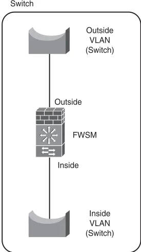
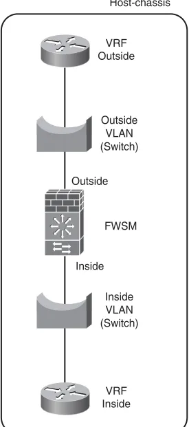
Virtualization
Virtualization or multiple-context mode allows the FWSM to be logically separated into multiple unique firewall instances as shown in Figure 2-1. These individual instances or contexts have a unique set of policies, IP addressing, static routes, and configurations. Because each context is unique, using the same IP addresses is allowed. This provides tremendous flexibility when adding new services or customers that may need to be separated from other contexts because of a security policy or for management reasons.
Using virtualization, you can consolidate multiple firewall appliances into a single line-card on the host chassis. Considering that the FWSM supports up to 250 contexts, how much rack space, power, and cooling will that eliminate?
Many organizations are employing virtualization techniques, such as Multiprotocol Label Switching-Virtual Private Network (MPLS-VPN), Virtual Routing and Forwarding (VRF)-lite, and generic routing encapsulation (GRE), to logically separate applications, services, job functions, to provide a public transport, and so on. This gives them the advantage of not having to create a new physical infrastructure or manage complex access lists every time a function needs to be isolated from the others.
Virtualization techniques are not only being deployed in the campus and wide-area network (WAN), but also within the datacenter to logically isolate applications and services. Using the FWSM in this scenario is particularly advantageous because of the amount of space and power it saves.
Table 2-4 Single/Multiple Context Rule Limits (Based on 12 Partitions)
Specification Single Multiple
AAA rules 6451 992
Access Control Entry (ACE) 72,806 11,200
ACE downloadable 5K 5K
Established rules 460 70
Filter rules 2764 425
Hypertext Transfer Protocol (HTTP), Internet Control Message Protocol (ICMP), Telnet, and Secure Shell (SSH) rules
1843 283
Policy NAT ACE 283 283
Figure 2-1 Virtualization (Multiple-Context Mode)
Comparing the FWSM to Other Security Devices
You should consider several factors when choosing the appropriate device to provide firewall functionality. These factors include the applications and security policies that need to be supported, device capabilities, future feature requirements, longevity of the product, cost, reuse, familiarity with the equipment, operational integration, training, and so on. Addressing the technical aspect is as follows—you are on your own for the rest!
The FWSM, Internetwork Operating System Firewall (IOS FW), Private Internet Exchange (PIX), and Adaptive Security Appliance (ASA) all provide similar capabilities in the support of stateful application and protocol inspection, Network Address Translation (NAT) and Port Address Translation (PAT), routing, content filtering, and user
authentication and authorization. The FWSM does not support Virtual Private Network (VPN) termination except for use in management, whereas the PIX, ASA, and IOS-based devices all have that capability.
Obviously, creating a feature list that is completely inclusive is beyond the scope of this book. The objective is to provide a general guideline for selecting the appropriate platform to match the solution.
Choosing the appropriate security device requires that you not only have a good understanding of the scope of the project but of the capabilities of the hardware, too. Keeping up to date on the technologies will definitely help you be successful.
FWSM
Context A: In Routed Mode
Comparing the FWSM to Other Security Devices 25
IOS FW
Routers starting with the 800 series through the 7600 (SX code) and including the 7200 and 7300 series and the 6500 series switch support IOS FW.
NOTE Be sure to check the appropriate documentation for the specific hardware and software you plan to deploy.
IOS FW is usually deployed on branch office routers by customers that are looking for a one-box solution. IOS provides many other capabilities, such as voice gateways, GRE, Internet Protocol Security (IPsec), Advanced Encryption Standard (AES), Secure Sockets Layer (SSL), Virtual Private Network (VPN), Multiprotocol Label Switching (MPLS), extensive routing protocol support, and so on. By combining these additional features, routers running IOS FW provide incredible flexibility and the option to quickly add new services as business requirements change.
IOS FW is a general-purpose firewall and not as robust as the purpose-built FWSM; therefore, it cannot match the performance capabilities and features like stateful failover.
In addition to the firewall feature set, IOS provides incredible flexibility and should be kept in your arsenal to defend your network.
PIX
The origin of the FWSM is the PIX, which finds its roots in the Finesse operating system. Many similarities exist between the FWSM, PIX, and ASA, including inspection engines, configuration of access lists, privileged levels, interface security levels, and so on. The most significant differentiator besides the form factor is that the FWSM does not support VPN (IPsec, AES, and SSL) termination.
If you are considering a PIX today, a better solution would be the next-generation appliance, the ASA.
ASA
Placement of the ASA is generally at the network edge in small, medium, and large network deployments. With its integrated capabilities, it makes an excellent security device for protecting services such as e-mail servers, web servers, user traffic, and so on.
With the integration of the FWSM in the 6500 or 7600, locating these device within the datacenter or protecting resources internal to the network is very common.
Taking a holistic approach to firewall security and leveraging the capabilities of the IOS FW, PIX, ASA, and FWSM provide a defense-in-depth security strategy. A complete defense-in-depth strategy is beyond the scope of this book. For additional information on the Security Architecture for Enterprise (SAFE) documentation, go to http://
www.cisco.com/go/safe.
Hardware Architecture
The architecture of the FWSM consists of four major components: Network Processors (NP) 1A (NP1A) and 1B (NP1B), Network Processor 2 (NP2), and the Processor running the FWSM code (FWSM-complex).
The FWSM is connected to the backplane of the 6500 or 7600 through a full-duplex 6-gigabit EtherChannel (GEC), totaling 12 gigabits of bandwidth using marketing math. A 3 Gb connection is established to NP1A and also to NP1B from the backplane.
One item of consideration is the use of GEC to load-share traffic. The GEC load-sharing algorithm by default for non-IP traffic is an exclusive-OR (XOR) of the source and destination Media Access Control (MAC) addresses, and for IP traffic it is an XOR of the source and destination IP addresses. This will cause the traffic flow from a single source to a single destination to use only one of the gigabit connections. If you are testing
performance numbers, recognize that you will need multiple source/destination pairs for traffic to load-share across the GEC.
To determine how the EtherChannel is configured, use the show etherchannel load-balance module command as shown in Example 2-1.
Example 2-1 Determining EtherChannel Configuration
6500# sshsshhhoowoow ww eeteettthhehhereerrrcccchhhhaanaannnnnenneeellll llolloaooaaadddd--b--bbbaalaalllaanaancnncccee ee mmommodooddduuuullllee module-numberee EtherChannel Load-Balancing Configuration:
src-dst-ip mpls label-ip
EtherChannel Load-Balancing Addresses Used Per-Protocol: Non-IP: Source XOR Destination MAC address
Hardware Architecture 27
NP1A and NP1B can handle 3 million packets per second and perform Layer 2 checking by verifying that the destination of the frame is either the MAC address of the FWSM or a broadcast/multicast address. They also verify whether the destination IP address of the packet is associated with the FWSM.
Routing protocol packets and any non-Transmission Control Protocol (TCP)/User Datagram Protocol (UDP)/ICMP traffic will be sent to the FWSM-complex. A session lookup is done on TCP/UDP/ICMP traffic, and if session information is not available, one of four of the following will occur:
•
If the packet is not a TCP Synchronize Sequence Number (SYN) (the first packet in the TCP 3-way handshake), it will be dropped.•
If the packet is UDP or TCP SYN, send it to NP2.If the packet is ICMP, verify against ACL or permit ICMP statement.
•
If the packet is routing information, send it to FWSM-complex.•
If the packet is a fragment, send it to the virtual reassembly process on NP1A/B.•
Control messages are also sent to NP2.If the session information is available, take the following action:
•
If the packet requires “protocol-inspection,” send it to the FWSM-complex.•
If the packet is network management associated with the FWSM, send it to NP2.•
If the packet is a fragment, send it to the virtual reassembly process on NP1A/B.•
Perform a packet rewrite and if necessary, modify TCP information and checksum (TCP protocol-inspection), execute NAT/PAT rewrite, add Layer 2 information, and send it to the host-chassis. Any traffic that follows this flow is said to be in the “fast or accelerated path.”NP2 can sustain 100K new connections per second. It also matches against ACL entries, performs route lookup, maintains the AAA cache, TCP intercept, Reverse Path Forwarding (RPF) checks, and translation address pool allocation. Traffic that follows this flow is in the “session management path.”
Packets received from NP1A/B that can be processed on the NP2 will be returned to NP1A/ B. Packet forwarding is based on the following criteria: