51 High-Tech
Evil Genius Series
Bionics for the Evil Genius: 25 Build-It-Yourself Projects
Electronic Circuits for the Evil Genius: 57 Lessons with Projects Electronic Gadgets for the Evil Genius: 28 Build-It-Yourself Projects Electronic Games for the Evil Genius
Electronic Sensors for the Evil Genius: 54 Electrifying Projects 50 Awesome Auto Projects for the Evil Genius
50 Model Rocket Projects for the Evil Genius 51 High-Tech Practical Jokes for the Evil Genius Fuel Cell Projects for the Evil Genius
Mechatronics for the Evil Genius: 25 Build-It-Yourself Projects
MORE Electronic Gadgets for the Evil Genius: 40 NEW Build-It-Yourself Projects 101 Outer Space Projects for the Evil Genius
101 Spy Gadgets for the Evil Genius
123 PIC®Microcontroller Experiments for the Evil Genius
123 Robotics Experiments for the Evil Genius PC Mods for the Evil Genius
Radio and Receiver Projects for the Evil Genius Solar Energy Projects for the Evil Genius
BRAD GRAHAM
KATHY M
C
GOWAN
51 High-Tech
Practical Jokes for
the Evil Genius
New York Chicago San Francisco Lisbon London Madrid Mexico City Milan New Delhi San Juan Seoul
Copyright © 2008 by The McGraw-Hill Companies, Inc. All rights reserved. Manufactured in the United States of America. Except as permitted under the United States Copyright Act of 1976, no part of this publication may be reproduced or distributed in any form or by any means, or stored in a data-base or retrieval system, without the prior written permission of the publisher.
0-07-159552-X
The material in this eBook also appears in the print version of this title: 0-07-149494-4.
All trademarks are trademarks of their respective owners. Rather than put a trademark symbol after every occurrence of a trademarked name, we use names in an editorial fashion only, and to the benefit of the trademark owner, with no intention of infringement of the trademark. Where such designations appear in this book, they have been printed with initial caps.
McGraw-Hill eBooks are available at special quantity discounts to use as premiums and sales promotions, or for use in corporate training programs. For more information, please contact George Hoare, Special Sales, at [email protected] or (212) 904-4069.
TERMS OF USE
This is a copyrighted work and The McGraw-Hill Companies, Inc. (“McGraw-Hill”) and its licensors reserve all rights in and to the work. Use of this work is subject to these terms. Except as permitted under the Copyright Act of 1976 and the right to store and retrieve one copy of the work, you may not decompile, disassemble, reverse engineer, reproduce, modify, create derivative works based upon, transmit, distribute, disseminate, sell, publish or sublicense the work or any part of it without McGraw-Hill’s prior consent. You may use the work for your own noncommercial and personal use; any other use of the work is strictly prohibited. Your right to use the work may be terminated if you fail to comply with these terms.
THE WORK IS PROVIDED “AS IS.” McGRAW-HILL AND ITS LICENSORS MAKE NO GUARANTEES OR WARRANTIES AS TO THE ACCURACY, ADEQUACY OR COMPLETENESS OF OR RESULTS TO BE OBTAINED FROM USING THE WORK, INCLUDING ANY INFORMATION THAT CAN BE ACCESSED THROUGH THE WORK VIA HYPERLINK OR OTHERWISE, AND EXPRESSLY DISCLAIM ANY WARRANTY, EXPRESS OR IMPLIED, INCLUDING BUT NOT LIMITED TO IMPLIED WARRANTIES OF MERCHANTABILITY OR FITNESS FOR A PARTICULAR PURPOSE. McGraw-Hill and its licensors do not warrant or guarantee that the functions contained in the work will meet your requirements or that its operation will be uninterrupted or error free. Neither McGraw-Hill nor its licensors shall be liable to you or anyone else for any inaccuracy, error or omission, regardless of cause, in the work or for any damages resulting therefrom. McGraw-Hill has no responsibility for the content of any information accessed through the work. Under no circumstances shall McGraw-Hill and/or its licensors be liable for any indirect, incidental, special, punitive, consequential or similar damages that result from the use of or inability to use the work, even if any of them has been advised of the possibility of such damages. This limitation of liability shall apply to any claim or cause whatsoever whether such claim or cause arises in contract, tort or otherwise.
Brad Grahamis an inventor, robotics hobbyist, founder and host of the ATOMICZOMBIE.COM web site (which receives over 2.5 million hits monthly), and a computer professional. He is the co-author, with Kathy McGowan, of 101 Spy Gadgets for the Evil Genius,Atomic Zombie’s Bicycle Builder’s Bonanza(perhaps the most creative bicycle-building guide ever written), and
Build Your Own All-Terrain Robot, all from McGraw-Hill. Technical manager of a high-tech firm that specializes in computer network setup and maintenance, data storage and recovery, and security services, Mr. Graham is also a Certified
Netware Engineer, a Microsoft Certified Professional, and a Certified Electronics and Cabling Technician.
Kathy McGowanprovides administrative, logistical, and marketing support for Atomic Zombie’sTMmany robotics, bicycle, technical,
and publishing projects. She also manages the daily operations of a high-tech firm and several web sites, including ATOMICZOMBIE.COM, as well as various Internet-based blogs and forums. Additionally, Ms. McGowan writes articles for e-zines and is collaborating with Mr. Graham on several film and television projects.
Our Evil Genius collaborator Judy Bass at
McGraw-Hill has always been our biggest fan and we can’t thank her enough for believing in us every step of the way. A heartfelt thank you to Judy and everyone at McGraw-Hill for helping to make this project a reality. Thanks also to all of you who contact us, especially members of the “Atomic Zombie Krew,” our international family of
Evil Geniuses, bike builders, and robotics junkies. We sincerely appreciate your support, friendship, and feedback. You’re the best creative “krew” in the world.
There are many projects, a blog, videos, a builder’s gallery, and support at ATOMICZOMBIE.COM. We always look forward to seeing what other Evil Geniuses are up to. Hope to see you there!
Acknowledgments
Cool stuff, cool people!
1 Introduction 1
Warranty Void! 1 Basic Electronics 2
2 Truly Annoying Devices 17
Project 1—The Dripping Faucet 17 Project 2—Evasive Beeping Thing 20 Project 3—Ghost Door Knocker 24 Project 4—Putrid Stink Machine 28
3 Critters and Beasties 33
Project 5—Alive and Breathing 33 Project 6—Hairy Swinging Spider 36 Project 7—Carpet Crawling 40
Creature
Project 8—Universal Critter 44 Launcher
Project 9—Trash Can Troll 48
4 Mechanical Mayhem 51
Project 10—Remote Control 51 Jammer
Project 11—Radio Station Blocker 54 Project 12—Video Fubarizer 57 Project 13—Audio Distorter 59 Project 14—Phone Static Injector 61 Project 15—Hard Drive Failure 63 Project 16—Serious Car 68
Troubles
5 Things That Go Bump in the Night 71
Project 17—Glowing Blinking Eyes 71 Project 18—Computer Audio 76
Nightmare
Project 19—Rats in the Walls 82 Project 20—Footsteps in the Night 84 Project 21—Giant Shadow 86
Projector
6 Evil Abounds! 91
Project 22—Voices from the Grave 91 Project 23—Evil-Possessed Doll 95 Project 24—Telephone Devil Voice 98 Project 25—Evil Lurching Head 101 Project 26—Give Us a Sign! 104 Project 27—Flying Ouija Board 107
7 Shock and Awe! 113
Project 28—The Barbeque Box 113 Project 29—Simple Induction Shocker 115 Project 30—Strong Pulse Shocker 117 Project 31—Disposable Camera Zapper 120 Project 32—Hissing Gas Container 124 Project 33—Radiation Detector 127
8 Machine Hoaxes 133
Project 34—The Magic Light Bulb 133 Project 35—Coin-Minting Machine 136 Project 36—See Through Walls 142
9 Mind Benders 147
Project 37—Rigged Lie Detector 147 Project 38—The Dog Talker 149 Project 39—Telepathy Transmitter 153 Project 40—Subliminal Audio 157
Mind Control
Project 41—Subliminal Video 160 Mind Control
10 Halloween Horrors 165
Project 42—Flying Vampire Bat 165 Project 43—The Haunted Ghost Mirror 170 Project 44—Living Brain in a Jar 172 Project 45—Universal Motivator 176 Project 46—Sound-activated Switch 179 Project 47—Flesh-eating 181
Jack-O-Lantern
Contents
Contents
11 Fluffy Attacks! Scare Them Silly! 187
Project 48—Spring-Loaded 188 Launch Pad
Project 49—Trap Door Cage 190 Project 50—Light-activated Trigger 193 Project 51—Fluffy’s Body 198
12 Digital Fakery 203
Editing Software 203 Original Photo Quality 204 Warping Effects 204 Making Hoax Photos 206 Adding Reflections and Shadows 212
51 High-Tech
Introduction
Chapter 1
Warranty void!
This book was written for all those who feel the irresistible urge to break open the case to see what makes that appliance or electronic device work. “There are no user serviceable parts inside,” or “disassembly will void the warranty” are phrases that simply fuel the fire for us hardware-hacking Evil Geniuses. The ability to make an electronic or mechanical device do things that it was not intended for is a skill that is easily learned by anyone who is not afraid to put his or her crazy ideas to the test, and possibly blow a few fuses or fry a few circuits along the way. You do not need an engineering degree or a room full of sophisticated tools to become a successful hardware hacker, just the desire to create, a good imagination and a large pile of junk to experiment with.
A warped sense of humor can be a venerable force when mixed with the ability to turn evil mechanical ideas into real-world working devices. I believe that if you are planning to do something, you should make it count. As all of my once-unsuspecting friends can attest to, this attitude applies to my practical jokes as well. Of course, you must remember the “golden rule,” and expect that your practical joke victims will some day turn the tables on you. You never know who might have a copy of this book, and a list with your name on it! Of course, all of the evil ideas in this book are designed to be harmless, even though some of them may be quite elaborate in nature. Knowing when not to launch a prank, and learning to weed out those who have no sense of humor is also a skill that should be practiced, and you will have a great time with the projects in this book.
If you have never cracked the case on an electronic device, or have never wielded the unlimited power of the almighty soldering iron, then fear not—I have not used any rare parts or special tools, just hardware store parts, common appliances and basic tools. To gain the most from this book, don’t be afraid to alter the projects to suit your needs. You can mix and match different projects to create thousands of new devices to perform your evil bidding. This is hacking after all, and it would be unbecoming of an Evil Genius to fully follow the instructions. Another thing you may notice that is missing from this book is a rigid parts list. Rather than specifying a “50-megawatt ruby laser” (only available from a particular website or store), I have tried to use only the most common parts found by butchering standard easy-to-find appliances or parts found off the shelf from any hardware store. Also, many of the parts can be substituted for similar parts that will do the same job and, as you get better at hacking and inventing, you will be able to turn just about any pile of junk into something wonderful. This way, you can work with what you have available without breaking your budget in the process, or spending weeks waiting for some overpriced exotic part to arrive in the mail from afar.
forums on the Internet, as there is a wealth of knowledge, and many experienced members who may be willing to answer your questions. If you are a “newbie,” don’t let that fact discourage you from seeking answers; even the brightest electronic engineers could not identify the positive terminal on a capacitor at one point in their early careers.
Well, that pretty much sums up my introduction. Just take your time, feel free to experiment, and don’t be afraid to put your ideas into motion! The basic electronics theory that follows covers most of the technology used in this book, and can be used to create just about any electronic device imaginable, since many large circuits are nothing more than many smaller simpler circuits working together.
Basic electronics
Electronics is the art of controlling the electron, and semiconductors are the tools that make this possible. “Semiconductor” is the name given to the vast quantity of various components used to generate, transform, resist and control the flow of electrons in order to achieve some goal. If you have ever had the chance to look at a large main board from a device such as a computer or video player, then you would have seen the vast city of semiconductors interconnected by thousands of tiny wires scattered around the circuit board that holds them all in place. At first glance, this intricate city of complexity may be overwhelming and impossible to understand, but in reality, all of these semiconductors do a very basic task by themselves, and these tasks are not hard to
understand once you know the basics. Even a very complex integrated circuit with hundreds of tiny pins, such as a 1 million gate FPGA, is nothing more than a collection of smaller semiconductors such as resistors and transistors densely packed into a microscopic area using state of the art manufacturing processes. Having an understanding of the most basic electronic building blocks will
allow you to understand even the most complex designs. I am not going to dig as far down as atomic theory or how the various components are manufactured since that would double the size of this book and bore you to tears. I will, however, cover each of the most basic semiconductors that form the building block of many larger circuits as well as the tools and techniques that you will need to work with them. If you want to dig deeper into electronics theory, then find a nice thick book loaded with formulas or spend some time on the Internet researching the areas that may interest you—the wealth of knowledge on the Internet regarding electronics and hardware hacking in general is as far reaching as the ends of the galaxy! Now, let’s start by covering the mandatory tools and techniques you will need for this hobby.
Basic tools
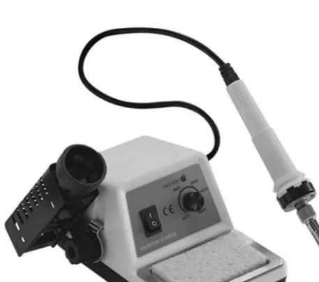
If you do not already have a soldering iron, then drop this book and head down to your local hobby or electronics store and get one because you will not be able to build even the most basic circuit without one. Of course, like any tool of the trade, you can get a basic model for a few bucks, or go for the deluxe model with all the bells and whistles such as digital heat control, ergonomic grip and who knows what else. The soldering iron shown in Figure 1-1 would be considered medium quality, and it comes with a holster and basic heat control.
I will admit that I have never owned anything more than a $10 black handle soldering iron and have built some very small circuit boards using surface-mounted components without any real problem. I am not saying that you shouldn’t spend the money for a quality soldering station, it is indeed worth it, but not absolutely necessary to get started. To feed your soldering iron, you will need a roll of “flux” core solder, which is probably the only type you will find at most hobby or
electronics supply outlets. Flux is a reducing agent designed to help remove impurities (specifically oxidized metals) from the points of contact to
improve the electrical connection between the semiconductor lead and the copper traces on a circuit board. Flux core solder is manufactured as a hollow tube and filled with the flux so that it is applied as you melt the solder. Solder used for electronics work is not the same as the heavy solid type used for plumbing, which is meant to be applied with a torch or high-heat soldering gun. The solder you will need will only be a millimeter in diameter and probably come on a small spool or coiled up in a plastic tube with a label that reads something like 40/60, indicating the percentage of
tin and lead in the solder. With a decent soldering iron and a roll of flux core solder, you will be able to remove and salvage semiconductors from old circuit boards or create your own circuits from scratch using pre-drilled copper-plated boards or by simply soldering the leads together with wires. There is one more soldering tool which I find to be a lifesaver, especially if you do a lot of circuit design and do not like waiting for days for some oddball value semiconductor to arrive in the mail. This tool, shown in Figure 1-2, is a spring-activated vacuum and is commonly called a “solder sucker.”
When you are salvaging components from old circuit boards, it can be very difficult to extract the ones that have more than a few leads by simply heating up the solder side of the board as you pull on the component, so you will have to find a way to extract the solder from each lead to free the component. The solder sucker does a marvelous job of removing the molten solder by simply pressing down on the lever once the spring has been loaded to create a vacuum, which draws the molten solder into the tube and away from the circuit board and component leads. Using this simple heat and suck process, you can remove parts with many leads, such as large integrated circuits, with great speed and ease, and without
Introduction
[image:18.603.37.266.234.436.2]Figure 1-1 Soldering iron with heat control
much risk of overheating the component or fine copper traces. Figure 1-3 shows the solder sucker removing the solder from the last leg of an 8-pin op amp of some defunct DVD player main board. When you build up a nice stock of circuit boards, you will save a ton of time and money when you want a part that would normally have to be ordered.
Considering a typical DVD player or VCR main board could have 500 resistors, 100 capacitors, 50 transistors and diodes, and hundreds of other useful components, this handy solder sucker can turn a discarded electronic appliance into hundreds of dollars worth of semiconductors, so collect as many old circuit boards as you have room for. Most of the semiconductors used for the various projects in this book came from old circuit boards, and it is not very often that I have to order new parts unless working on a cutting-edge design or something really non-standard.
Now, there is one last tool you will need to have in your electronics toolkit, and this is a multi-meter, which can measure voltage, resistance, and possibly capacitance and frequency. It’s pretty hard to troubleshoot a failing circuit without some kind of voltage test, and you will certainly need to measure impedance when checking the values of semiconductors such as resistors, coils, transistors and diodes. Even the most basic and inexpensive
[image:19.603.350.456.36.259.2]multi-meter will have these functions. Of course, you can find a lot more in a desktop multi-meter, and it usually boils down to how much you are willing to spend vs. what you really need. I have a basic hardware-store variety digital multi-meter (Figure 1-4) that can measure AC and DC voltage, amperage, resistance, capacitance and frequencies up to 10 MHz. This unit is considered entry level, and does the job for 90 percent of all the analog and digital projects that I tinker with. When I really get deep into the high-speed circuitry such as radiofrequency devices or high-speed microcontrollers, I find myself using an oscilloscope to examine microsecond timings and extremely weak analog signals, but for basic electronic circuits such as those presented in this book, an oscilloscope will not be necessary.
So there you have it—with a soldering iron, a roll of solder, a solder sucker, a basic multi-meter, and a pile of old circuit boards, you can build just about anything you want as long as you have the basic know how and patience. Now, let’s have a look at what the most common semiconductors do, and learn how to identify them.
Introduction
Figure 1-3 Removing an integrated circuit with the solder sucker tool
Resistors
Resistors, like the ones shown in Figure 1-5, are the most basic of the semiconductors you will be using, and they do exactly what their name implies—they resist the flow of current by exchanging some current for heat, which is dissipated through the body of the device. On a large circuit board, you could find hundreds of resistors populating the board, and even on tiny circuit boards with many surface-mounted components, resistors will usually make up the bulk of the semiconductors. The size of the resistor generally determines how much heat it can
dissipate and will be rated in watts, with 1⁄ 4and 1⁄
8watts being the most common type you will
work with (the two bottom resistors in Figure 1-5). Resistors can become very large, and will require ceramic-based bodies, especially if they are rated for several watts or more, like the 10-watt unit shown at the top of Figure 1-5.
Because of the recent drive to make electronics more “green” and power-conservative, large, power-wasting resistors are not all that common in consumer electronics these days, since it is more efficient to convert amperage and voltage using some type of switching power supply or regulator
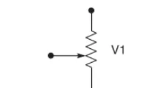
rather than by letting a fat resistor burn away the energy as heat. On the other hand, small-value resistors are very common, and you will find yourself dealing with them all of the time for simple tasks such as driving an LED with limited current, pulling up an input pin to a logical “one” state, biasing a simple transistor amplifier, and thousands of other common functions. On most common axial lead resistors, like the ones you will most often use in your projects, the value of the resistor is coded onto the device in the form of four colored bands which tell you the resistance in “ohms.” Ohms are represented using the Greek omega symbol (Ω), and will often be omitted for values over 99 ohms, which will be stated as 1K, 15K, 47K, or some other number followed by the letter K, indicating the value is in kilo ohms (thousands of ohms). Similarly, for values over 999K, the letter M will be used to show that 1M is actually 1 mega ohm, or one million ohms. In a schematic diagram, a resistor is represented by a zigzag line segment as shown in Figure 1-6, and will either have a letter and a number such as R1 or V3 relating to a parts list, or will simply have the value printed next to it such as 1M, or 220 ohms. The schematic symbol on the left of Figure 1-6 represents a variable resistor, which can be set from zero ohms to the full value printed on the body of the variable resistor.
A variable resistor is also known as a
“potentiometer,” or “pot,” and it can take the form of a small circuit-board mounted cylinder with a slot for a screwdriver, or as a cabinet-mounted can with a shaft exiting the can for mating with some type of knob or dial. When you crank up the volume on an amplifier with a knob, you are turning a potentiometer. Variable resistors are great
Introduction
Figure 1-5 Several typical resistors
[image:20.603.348.455.35.98.2]V1 R1
for testing a new design, since you can just turn the dial until the circuit performs as you want it to, then remove the variable resistor to measure the impedance (resistance) across the leads in order to determine the best value of fixed resistor to install. On a variable resistor, there are usually three leads: the outer two connect to the fixed carbon resistor inside the can, which gives the variable resistor its value, and a center pin that connects to a wiper,
allowing the selection of resistance from zero to full. Several common variable resistors are shown in Figure 1-7, with the top left unit dissected to show the resistor band and wiper.
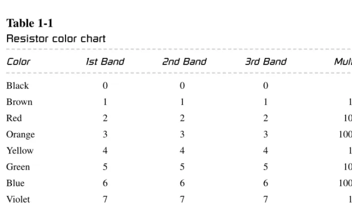
As mentioned earlier, most resistors will have four color bands painted around their bodies, which can be decoded into a value as shown in Table 1-1. At first, this may seem a bit illogical, but once you get the hang of the color
[image:21.603.98.453.489.694.2]Introduction
Figure 1-7 Common variable resistors
Table 1-1
Resistor color chart
Color 1st Band 2nd Band 3rd Band Multiplier
Black 0 0 0
Brown 1 1 1 1 Ω
Red 2 2 2 10 Ω
Orange 3 3 3 100 Ω
Yellow 4 4 4 1 KΩ
Green 5 5 5 10 KΩ
Blue 6 6 6 100 KΩ
Violet 7 7 7 1 MΩ
Gray 8 8 8 10 MΩ
White 9 9 9 0.1
Gold 0.01
band decoding, you will be able to recognize most common values at first glance without having to refer to the chart.
There will almost always be either a silver or gold band included on each resistor, and this will indicate the end of the color sequence, and will not become part of the value. A gold band indicates the resistor has a 5 percent tolerance (margin of error) in the value, so a 10K resistor could end up being anywhere from 9.5K to 10.5K in value, although in most cases will be very accurate. A silver band indicates the tolerance is only 10 percent, but I have yet to see a resistor with a silver band that was not on a circuit board that included vacuum tubes, so forget that there is even such a band! Once you ignore the gold band, you are left with three color bands that can be used to determine the exact value as given in Table 1-1. So let’s say we have a resistor with the color bands brown, black, red, and gold. We know that the gold band is the tolerance band and the first three will indicate the values to reference in the chart. Doing so, we get 1 (brown), 0 (black), and 100 ohms (red). The third band is the multiplier, which would indicate that the number of zeros following the first two values will be 2, or the value is simply multiplied by 100 ohms. This translates to a value of 1000 ohms, or 1K (10 ×100 ohms). A 370K resistor would have the colors orange, violet, and yellow followed by a gold band. You can check the value of the resistor when it is not connected to a circuit by simply placing your multi-meter on the appropriate resistance scale and reading back the value. I do not want to get too deep into
electronics formulas and theory here, since there are many good books dedicated to the subject, so I will simply leave you with two basic rules regarding the use of resistors: put them in series to add their values together, and put them in parallel to divide them. This simple rule works great if you are in desperate need of a 20K resistor, for
instance, but can only find two 10K resistors to put in series. In parallel, they will divide down to 5K. Now you can identify the most common
semiconductor that is used in electronics today, the resistor, so we will move ahead to the next most common semiconductor, the capacitor.
Capacitors
A capacitor in its most basic form is a small rechargeable battery with a very short charge and discharge cycle. Where a typical AAA battery may be able to power an LED for a month, a capacitor of similar size will power it for only a few seconds before its energy is fully discharged. Because capacitors can store energy for a predictable duration, they can perform all kinds of useful functions in a circuit, such as filtering AC waves, creating accurate delays, removing impurities from a noise signal, and creating clock and audio oscillators. Because a capacitor is basically a battery, many of the large ones available look much like batteries with two leads connected to one side of a metal can. As shown in Figure 1-8, there are many sizes and shapes of capacitors, some of which look like small batteries.
Just like resistors, capacitors can be as large as a coffee can, or as small as a grain of rice, it really depends on the value. The larger devices can store a lot more energy. Unlike batteries, some
capacitors are non-polarized, and they can be inserted into a circuit regardless of current flow, while some cannot. The two different types of capacitors are shown by their schematic symbols
Introduction
in Figure 1-9, C1 being a non-polarized type, and C2 a polarized type. Although there are always exceptions to the rules, generally the disk-style capacitors are non-polarized, and the larger can-style electrolytic types are polarized. An obvious indicator of a polarized capacitor is the negative markings on the can, which can be clearly seen in the larger capacitor shown at the top of Figure 1-8.
Another thing that capacitors have in common with batteries is that polarity is very important when inserting polarized capacitors into a circuit. If you install an electrolytic capacitor in reverse and attempt to charge it, the part will most likely heat up and release the oil contained inside the case causing a circuit malfunction or dead short. In the past, electrolytic capacitors did not have a pressure release system, and would explode like firecrackers when overcharged or installed in reverse, leaving behind a huge mess of oily paper and a smell that was tough to forget. On many capacitors, especially the larger can style, the voltage rating and capacitance value is simply stamped on the case. A capacitor is rated in voltage and in farads, which defines the capacitance of a dielectric for which a potential difference of one volt results in a static charge of one coulomb. This may not make a lot of sense until you start
messing around with electronics, but you will soon understand that typically, the larger the capacitor, the larger the farad rating will be, thus the more energy it can store. Since a farad is quite a large value, most capacitors are rated in microfarads (µF), such as the typical value of 4700 µF for a large electrolytic filter capacitor, and 0.1µF for a small ceramic disk capacitor. Picofarads (pF) are also used to indicate very small values such as those found in many ceramic capacitors or adjustable capacitors used in radiofrequency
circuits (a pF is one millionth of a µF). On most can-style electrolytic capacitors, the value is simply written on the case and will be stated in microfarads and voltage along with a clear indication of which lead is negative. Voltage and polarity are very important in electrolytic capacitors, and they should always be inserted correctly, with a voltage rating higher than
necessary for your circuit. Ceramic capacitors will usually only have the value stamped on them if they are in picofarads for some reason, and often no symbol will follow the number, just the value. Normally, ceramic capacitors will have a three-digit number that needs to be decoded into the actual value, and this evil scheme works as shown in Table 1-2.
Who knows why they just don’t write the value on the capacitor? I mean, it would have the same amount of digits as the code! Oh well, you get used to seeing these codes, just like resistor color bands, and in no time will easily recognize the common values such as 104, which would indicate a 0.1 µF value according to the chart. Capacitors behave just like batteries when it comes to parallel and series connections, so, in parallel, two
identical capacitors will handle the same voltage as a single unit, but double their capacitance rating, and in series they have the same capacitance rating as a single unit, but can handle twice the voltage. So if you need to filter a really noisy power supply, you might want to install a pair of 4700 µF
capacitors in parallel to end up with a capacitance of 9400 µF. When installing parallel capacitors, make sure that the voltage rating of all the capacitors used are higher than the voltage of that circuit, or there will be a failure.
Diodes
Diodes allow current to flow through them in one direction only so they can be used to rectify AC into DC, block unwanted current from entering a device, protect a circuit from a power reversal, and even give off light in the case of light-emitting
Introduction
C1 + C2
diodes (LEDs). Figure 1-10 shows various sizes and type of diodes including an easily
recognizable LED and the large full-wave rectifier module at the top. A full-wave rectifier is just a block containing four large diodes inside.
Like most other semiconductors, the size of the diode is usually a good indication of how much
current it can handle before failure, and this information will be specified by the manufacturer by referencing whatever code is printed on the diode to some data sheet. Unlike resistors and capacitors, there is no common mode of
identifying a diode unless you get to know some of the most common manufacturers’ codes by
Introduction
10 pf 10 or 100
12 pf 12 or 120
15 pf 15 or 150
18 pf 18 or 180
22 pf 22 or 220
27 pf 27 or 270
33 pf 33 or 330
39 pf 39 or 390
47 pf 47 or 470
58 pf 58 or 580
68 pf 68 or 680
82 pf 82 or 820
100 pf 101
120 pf 121
150 pf 151
180 pf 181
220 pf 221
270 pf 271
330 pf 331
390 pf 391
470 pf 471
560 pf 561
680 pf 681
820 pf 821
0.001µF 102
0.0012µF 122
(1200 pf)
0.0015µF 152
0.0018µF 182
(1800 pf)
0.0022µF 222
0.0027µF 272
0.0033µF 332
0.0039µF 392
0.0047µF 472
0.0056µF 562
0.0068µF 682
0.0082µF 822
0.01µF 103
0.012µF 123
0.015µF 153
0.018µF 183
0.022µF 223
0.027µF 273
0.033µF 333
0.039µF 393
0.047µF 473
0.056µF 563
0.068µF 683
0.082µF 823
0.10µF 104
0.12µF 124
0.15µf 154
0.18µF 184
0.22µF 224
0.27µF 274
0.33µF 334
0.39µF 394
0.47µF 474
0.56µF 564
0.68µF 684
0.82µF 824
1µF 105 or 1µF
Table 1-2
Ceramic capacitor value chart
memory, so you will be forced to look up the data sheet on the Internet or in a cross-reference catalog to determine the exact value and purpose of unknown diodes. For example, the NTE6248 diode shown in Figure 1-10 in the TO220 case (left side of photo) has a data sheet that indicates it is a Schottky barrier rectifier with a peak reverse-voltage maximum of 600 volts and a maximum forward current rating of 16 amps. Data sheets will tell you everything you need to know about a particular device, and you should never exceed any of the recommended values if you want a reliable circuit. The schematic symbol for a diode is shown in Figure 1-11, D1 being a standard diode, and the other a light-emitting diode (the two arrows represent light leaving the device).
The diode symbol shows an arrow (anode) pointing at a line (cathode), and this will indicate which way current flows (from the anode to the cathode, or in the direction of the arrow). On many small diodes, there will be a stripe painted around the case to indicate which end is the cathode,
and on LEDs, there will be a flat side on the case nearest the cathode lead. LEDs come in many different sizes, shapes, and wavelengths (colors), and have ratings that must not be exceeded in order to avoid damaging the device. Reverse voltage and peak forward current are very important values that must not be exceeded when powering LEDs or damage will easily occur, yet at the same time, you will want to get as close as possible to the maximum values if your circuit demands full performance from the LED, so read the data sheets on the device carefully. Larger diodes used to rectify AC or control large current may need to be mounted to the proper heat sink in order to operate at their rated values, and often the case style will be a clear indication due to the metal backing or mounting hardware that may come with the device. Unless you know how much heat a certain device can dissipate in open air, your best bet is to mount it to a heat sink if it was designed to be installed that way. Like most semiconductors, there are thousands of various sizes and types of diodes, so make sure you are using a part rated for your circuit, and double check the polarity of the device before you turn on the power for the first time.
Transistors
A transistor is one of the most useful
semiconductors available, and often the building block for many larger integrated circuits and components such as logic gates, memory and microprocessors. Before transistors became widely used in electronics, simple devices like radios and amplifiers would need huge wooden cabinets, consume vast amounts of power, and emit large wasteful quantities of heat due to the use of vacuum tubes. A vacuum-tube-based computer called ENIAC was once built that used 17,468 vacuum tubes, 7,200 crystal diodes, 1,500 relays, 70,000 resistors, 10,000 capacitors and had more than 5 million hand-soldered joints. It weighed 30 tons and was roughly 8 feet ×3 feet ×100 feet,
[image:25.603.102.197.275.325.2]Introduction
Figure 1-10 Several styles of diodes
D1 LED
and consumed 150 kW of power! A simple computer that would rival the power of this power hungry monster could easily be built on a few square inches of perforated board using a few dollars in parts today by any electronics hobbyist, thanks to the transistor. A transistor is really just a switch that can control a large amount of current by switching a small amount of current, thus creating an amplifier. Several common types and sizes of transistors are shown in Figure 1-12.
Depending on how much current a transistor is designed to switch, it may be as small as a grain of rice or as large as a hockey puck and require a massive steel heat sink or fan to operate correctly. There are thousands of varying transistor types and sizes, but one thing most of them have in common is that they will have three connections that can be called “collector,” “emitter” and “base,” and will be represented by one of the two schematic symbols shown in Figure 1-13.
The emitter (E), base (B) and collector (C) on both the negative-positive-negative (NPN) and positive-negative-positive (PNP) transistors do the same job. The collector/emitter current is controlled by the current flowing between the base and emitter terminals, but the flow of current is opposite in each device. Today, most transistors are NPN due to the fact that it is easier to manufacture a better NPN transistor than a PNP, but there are still occurrences when a circuit may use a PNP transistor due to the direction of current, or in tandem with an NPN transistor to create a matched pair. There is enough transistor theory to cover ten books of this size, so I will condense that information in order to help you understand the very basics of transistor operation. As a simple switch, a transistor can be thought of as a relay with no mechanical parts. You can turn on a high-current load such as a light or motor with a very weak current such as the output from a logic gate or light-sensitive photocell. Switching a large load with a small load is very important in electronics, and transistors do this perfectly and at speed that a mechanical switch such as a relay could never come close to achieving. A audio amplifier is nothing more than a very fast switch that takes a very small current such as the output from a CD player and uses it as the input into a fast switch that controls a large current such as the DC power source feeding the speakers. Almost any transistor can easily operate well beyond the frequency of an audio signal, so they are perfectly suited for this job. At much higher frequencies like those used in radio transmitters, transistors do the same job of amplification, but are rated for much higher frequencies sometimes into the gigahertz range. Another main difference between the way a mechanical switch and a transistor work is the fact that a transistor is not simply an on or off switch, it can operate as an “analog” switch, varying the amount of current switched by varying the amount of current entering the base of the transistor. A relay can turn on a 100-watt light bulb if a 5-volt current is applied to the coil, but a transistor could vary the intensity of the same light bulb from zero to full brightness depending on the voltage at the base.
Introduction
Figure 1-12 Various common transistors
B E C B C E
Q1 NPN Q2 PNP
Like all semiconductors, the transistor must be rated for the job you intend it to do, so maximum current, switching voltage and speed are factors that need to be considered when choosing the correct part. The data sheet for a very common NPN transistor, the 2N2222 (which can be
substituted for the 2N3904 often used in this book) is shown in Figure 1-14.
From this page, we can see that this
transistor can switch about half a watt (624 mW) with a voltage of 6 volts across the base and emitter junction. Of course, these are maximum ratings, so you might decide that the transistor will work safely in a circuit if it had to switch on a 120-mW LED from a 5-volt logic level input at the base. As a general rule, I would look at the
maximum switching current of a transistor, and never ask it to handle more than half of the rated maximum value, especially if it was the type of transistor designed to be mounted to a heat sink. The same thing applies to maximum switching
speed—don’t expect a 100-MHz transistor to oscillate at 440 MHz in an RF transmitter circuit, since it will have a difficult enough time just reaching the 100-MHz level.
Breadboards and circuit boards
Once you find a project and the parts needed to build it, you will need to connect all the leads from each semiconductor together in order to create the completed circuit. A commercial product will have a printed circuit board, perfectly made with one or more layers, and could contain thousands of semiconductors of all sizes including surface-mounted devices, each with hundreds of pins per package. A circuit board of this magnitude is well out of reach for the average hobby
builder, so unless you want to spend a few hundred dollars to have a single circuit board made, you will need to find another way to get those
Introduction
Rating Symbol Value Unit
Collector-Emitter Voltage VCEO 40 Vdc
Collector-Base Voltage VCBO 75 Vdc
Emitter-Base Voltage VEBO 6.0 Vdc
Collector Current—Continuous IC 600 mAdc
Total Device Dissipation @ TA = 25°C PD 625 mW
Derate above 25°C 5.0 mW/°C
Total Device Dissipation @ TC = 25°C PD 1.5 Watts
Derate above 25°C 12 mW/°C
Operating and Storage Juntion TJ,Tstg −55 to +150 °C Temperature Range
Characteristic Symbol Max Unit
Thermal Resistance, Junction to Ambient RθJA 200 °C/W
Thermal Resistance, Junction to Case RθJC 83.3 °C/W
MAXIMUM RATINGS
Amplifier Transistors
NPN Silicon THERMAL CHARACTERISTICSP2N2222A
Collector 1 3 Emitter 2 Base 1 2 3CASE 29–11, STYLE 17 TO–92 (TO–226AA)
semiconductors connected. Sure, you could send your design to one of those fast turnaround printed circuit board manufacturers that charge under a hundred dollars for a few boards, but what if you decide to change something, or realize one of the parts you planned to use is now in a different package layout? The best way to build a single circuit board is by simply hand wiring it to a bit of perforated board, especially if the parts count is low and there are now extremely high frequencies in use. Every project in this book that has a schematic diagram was built by placing the semiconductor leads through the holes on a bit of perforated board, and then soldering the underside using either the leads of each component, or a bit of wire. Figure 1-15 shows one of my “perf. board” projects built by dropping all the semiconductors on the board and wiring them on the underside. This device includes a
microprocessor with custom software that magically draws an image in mid-air using 32 pulsed LEDs as you wave the unit back and forth like a flag. If you want to know how a device like this works, search Google for “scanned LED”, or visit www.atomiczombie.com and check out LED scanner in the electronics projects section of our gallery.
This circuit may seem to be very complex, especially with all that wiring on the underside of
the board, but in reality, it is a very simply circuit, and all those wires connect the 32 LEDs to the LED driver chip. In the early days of computer design, entire 8-bit computer systems were built using this same technique, although they had thousands of wires. If there is a problem with a part, or some of the wiring, then just get out your soldering tools and fix it. The same easy repair would not happen on a printed circuit board, which can become a real problem for those who mass produce electronic devices. This perforated board can be purchased at any electronics supply or hobby shop in squares ranging in size from a few inches to a foot or more, and you can just snap off as much as you need for whatever circuit you plan to build. There are also prototyping circuit boards available that have solder pads on one or both sides so you can make a more permanent circuit board with a lot less hand wiring by connecting the pads together with solder. An example of this type of prototyping board is shown in Figure 1-16 with the components for one of my robot stepper motor drives on it.
You can also get “proto boards” with solder pads connected in rows: a very easy design, with
minimal wiring, as well as specially shaped blank cards for designing and testing circuits that might need to plug into a computer slot, or satellite dish. The fact is, there are plenty of ways to build most
Introduction
simple projects without having to spend a ton of money and time trying to acquire a professionally made printed circuit board. You could even go as far as etching your own copper boards into printed circuit boards, and there are numerous Internet resources that will show you how to do this, or sell complete kits based on chemical etching, or photo etching of copper plates. I rarely use the etching technique since it will have the same downfalls of
the professionally made circuit board when it comes to easy modification, and require a lot more work. If you are designing a circuit from scratch, or want to try a schematic found on the Internet, it may be a lot of work to solder all the components on a perf. board or proto board just to see if the thing even works, so many hobbyists start without any soldering at all using what is called a
“breadboard.” A typical breadboard will have many strips of interconnected electrical terminals, known as “bus strips,” down one or both sides, either as part of the main unit or as separate blocks clipped on to carry the power rails. This allows you to simply press the semiconductor leads into the breadboard and interconnect the circuit using small bits of wire with the insulation removed at each end. To make changes, simply move the wiring around. Figure 1-17 shows the solderless breadboard I used to develop all the circuits in this book and many hundreds of other projects.
Also shown in Figure 1-17 (inset) is the relationship between the connected strips and the holes in the board. The Atmel processor plugged into the top of the board would have every leg connected to a vertical strip of five interconnected
Introduction
Figure 1-16 A solder pad prototyping board
holes, so you can place a wire in any of the four open holes and make a connection to the pin on that strip. Breadboards are a hobbyist’s best friend, and I certainly recommend that you purchase one or more of them if you plan to make anything more complex than an LED flasher circuit. I have learned one important thing after owning several different models of breadboards—purchase a quality unit with a metal base or your high-speed circuits will fail. If you have a microprocessor clocked over 4 MHz, or any RF circuit on a breadboard, it will act glitchy on a cheap breadboard with no metal base due to stray and unpredictable capacitance. I have run processors over 40 MHz on my breadboard and designed working RF transmitters in the 500-MHz range with few problems other than a slight re-tuning after moving them to a real circuit board. Another tip that will save you a lot of messing around is that the perfect wire for these breadboards can be found by cutting up some CAT-5 network cable as shown in Figure 1-18. This solid core copper wire is inexpensive, easy to strip, color coded and
works perfectly in all breadboards that I have used over the years.
It is a good idea to cut up many various lengths of breadboarding wire ahead of time so you can concentrate on designing your circuit. Try to avoid stranded wire as well, since it will be difficult to insert into the holes and may tend to bunch up and make a faulty connection, which could be a real problem to track down.
Well, that’s it! With a handful of semiconductors, a breadboard and soldering iron, you should be able to create just about anything you like. Don’t give up every time blue smoke pours out of transistor, or when a circuit does something completely unexpected, it’s all part of this game. Learn as you go, using the Internet, reference books, and other people’s designs as a guide and, before long, you will be able to whip up any type of circuit without any reference material at all.
Let’s start building some truly annoying devices to help you hone your electronics skills.
Introduction
Truly Annoying Devices
Chapter 2
This device makes the sound of dripping water. It’s very difficult to find because it only makes a sound in complete darkness. The unit is very sensitive to any amount of light, so even the faint glow from a nearby night light will make it go silent, causing great frustration for the person who is trying to find the source of the leak. Build the unit into a small plastic box, or conceal it in a familiar kitchen or bathroom object, such as a cup or tissue box, to make finding the device even harder. The dripper will run for days on a single 9-volt battery, and will certainly drive anyone mad trying to locate it.
The unit is made using two common 555 timers—one that sends out a series of timed pulses when the lights are out, and another that makes a high-pitched chirp each time the pulse is sent. The rate of repetition can be set from several seconds to a few times per second so that the unit can be made to sound like a slow leak or a type of insect. The chirp frequency can be adjusted as well to tailor the sound to both the container used to hold the device and the type of “piezo element” used to produce the sound.
A piezo element is nothing more than a bit of piezoceramic material glued to a metal disk so that it will resonate when a current is applied. A piezo element by itself cannot generate any sound, which is why the second 555 timer is used as an audio oscillator. Piezo elements are easy to find at any electronics supplier, and in many electronic appliances such as microwave ovens,
cash registers, computers, digital watches (the back cover is the piezo element), and practically any device that makes a beep or blip sound. A piezo element is easy to identify, and it may come in several varieties as shown in Figure 2-1.
As shown in Figure 2-1, plastic-encased piezo elements come in sizes from less than an inch in diameter to several inches. The unit on the top right of the picture is the bare element, which can sometimes be found glued directly to the cabinets of some electronic devices such as telephones, toys or even the backs of digital-watch covers.
Sometimes it is easy to confuse an encased piezo element with an audio buzzer, since they often look the same. An audio buzzer is designed to make a sound as soon as power is applied, and because it already contains an audio oscillator, will often have a voltage rating or pin polarity stamped on the case. If you are not sure, just apply 5 or 9 volts (take note of the polarity if it is indicated on the case), and listen for a sound. A piezo element will only make a single pop, whereas a buzzer will produce a sound. Piezo elements are not polarity sensitive, so it does not matter which pin is positive or negative. Have a look at the schematic for the dripper as shown in Figure 2-2. I will explain how it works and how you can alter it to make different sounds.
As stated earlier in this section, there are two 555 timers used. The function of timer 1 is to create a series of pulses that vary between several
Project 1—The Dripping Faucet
Figure 2-1 Several piezo elements
+9 V
R1
R3
C1
C2
CDS cell
+
R2
R4 VR1
VR2
Gnd
Piezo buzzer
555 timer 1 555 timer 2
VR1: 5K VR2: 5K
R1: 1K R2: 1M R3: 1K R4: 22K
C1: 100 µF C2: 0.01µF
seconds each and several pulses per second. The pulse rate is controlled by setting variable resistor VR1 to the desired rate. Timer 1 will only begin to send pulses if there is no light in the area, since it is controlled by the CDS cell shown on pin 2, which will almost short the pin to ground when any light strikes its surface. When there is no light present, the CDS cell reaches a megaohm or more and the timer can resume its job of sending out pulses on pin 3, which feeds the second timer. The second timer is a basic audio oscillator that can be set to various high frequencies by adjusting variable resistor VR2. The output of timer 2 is sent directly to the piezo element on pin 3 to produce a very short duration high-pitched noise that sounds a lot like a water drop or a pest. If you want to play around with more varying sound frequencies and timing rates, then you can mess around with the values of VR1, VR2, R1 and R3 to make some very interesting sounds. Another thing that can alter the sound is the type of enclosure used. Sound waves will resonate differently depending on both the shape and material used to make the enclosure.
The dripper can be built on a bit of perforated board and hand wired as shown in Figure 2-3. It will run for many days connected to a good 9-volt
battery, but can run from as low as 5 volts, and as high as 12 volts without a problem.
Figure 2-3 shows the completed circuit ready to be engaged for hours of great fun at the expense of someone’s good night sleep! The circuit is simple enough to hand wire on the underside of the perforated board using some hookup wire and a soldering iron. Then, it was tested with a fresh battery and the lights off. If you find that the unit will not start when the lights are out, test first to ensure that there is sound output by removing the CDS cell completely, which will cause the unit to start dripping. When you reinstall the CDS, the unit will stay quiet until there is absolutely no light at all in the room. Even the smallest bit of light will silence the device, so if your target room has any ambient light, you will have to add a resistor in series with the CDS cell in order to make the unit less sensitive to ambient light. Try a 50–100K resistor or a variable 100K resistor in series with the CDS cell to help the unit switch on in a dimly lit environment. A little experimentation may be necessary, but once working, the dripper will spring into action as soon as the light is off and become silent as soon as someone turns on the light to investigate.
Project 1—The Dripping Faucet
Where to hide such a device? Well, there are so many possibilities. I found that an empty
deodorant case worked perfectly as shown in Figure 2-4. There was enough room for the battery, the piezo element, and the circuit board. Owing to the extreme sensitivity of the CDS cell and slightly opaque plastic, I did not even have to drill a hole for the CDS cell. The sound was also loud enough that a hole for the piezo element was not needed, especially since my covert container could exist in direct sight without detection. When you are cramming all of the guts into the enclosure, be careful that the underside of the circuit board does not touch anything conductive like the piezo metal or battery casing. Wrapping the circuit board in a bit of paper towel or fastening all the parts to the plastic may be a good idea, especially if you plan to move the unit around.
Figure 2-5 shows the completed dripping faucet device ready to ruin a good night’s sleep when the light goes out. This unit can even detect the hallway light, so it really is difficult to track down unless you have night vision goggles! In Figure 2-5, you can see the small switch that I added in series with one of the battery connections to turn the device off when it is not in use. If you want to expand the vocabulary of this device, you could add two cabinet mounted variable resistors for VR1 and VR2 to allow it to be turned into a cricket, mouse, fast drip, or just about any similar sound by simply turning the two knobs. Speed up the chirp, and hide the unit in a tent to simulate an insect infestation, or hide it in the trash can. Yes, the ways you can annoy your friends with this simple device are truly endless!
Project 2—Evasive Beeping Thing
Figure 2-4 The dripper circuit assembled
Project 2—Evasive Beeping Thing
The evasive beeping thing is appropriately named, since it dutifully does exactly what its name implies: it sends out a 5-second high-pitched beep every few minutes. The source is extremely
video screen, or even a beeping wrist watch buried deep in a couch. As you know, high-pitched sounds seem like they are coming from all directions, which makes tracking them to the source a real chore. Add the fact that the sound only happens once every several minutes, and it may drive a person loopy as they spend all day looking for the source of the sound. Well, that’s our goal anyhow! To generate the high pitch audio wave, a small speaker like those found in tiny electronic devices (cell phones, transistor radios or a tweeter from a small speaker system, etc.) will be connected to a simple audio oscillator set to a frequency near the upper limits of our audio capabilities. The
oscillator is triggered to run for approximately five seconds every few minutes by a 555 timer circuit with its output connected to the oscillator. The higher the frequency rating of the speaker, the farther the high-pitched sound will travel, which is why a two- or three-inch diameter tweeter is optimal for this project. The small speakers shown in Figure 2-6 are perfect for this project, and I included a piezo buzzer as described in the last project, as it can also be used with a simple modification of the oscillator circuit.
The rating of the small speaker is not important, since the audio oscillator will drive speakers from
4 to 16 ohm with very little power output. The speaker on the bottom left was the loudest of the ones that I tested since it was an actual tweeter removed from a small boom-box cabinet, and strictly designed to pass high frequencies. The speaker shown on the top left was the one I
decided to use in the final design though because it fit nicely into the cabinet I chose to help disguise the evil device. Now, let’s get on to the design of the electronics that make this unit work.
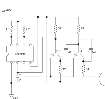
Figure 2-7 shows the schematic of the beeping thing, and you may recognize some similarities between this schematic and the last one, as they are based on similar parts and principals. In the schematic, the 555 is set up so that its output will turn on the two transistor audio oscillators formed by the pair of NPN transistors. Just like most 555 timer circuits, the timing cycle is controlled by the two resistors on pins 6, 7 and 8, and by the capacitor connected to pins 1 and 2. If you play around with the values of the two resistors, you can control the duty cycle of the timing pulses in order to alter both the off time and on time of the cycle to create more or less beep each time the cycle repeats. The capacitor controls the actual frequency of the timing pulses, and the larger the value, the longer the duration between each
[image:36.603.108.445.37.255.2]Project 2—Evasive Beeping Thing
Project 2—Evasive Beeping Thing
8 ohm speaker 555 timer
R1: 1M R2: 100K R3: 1K
R4: 100 ohm R5: 10K R6: 10K Q1: 2N3904 NPN
Q2: 2N3904 NPN
C1: 100 µF C2: 0.01 µF C3: 0.01 µF R1
+9 V
R2 R5 R6
R3 R4
Q1
C1
Gnd
+
[image:37.603.132.422.36.252.2]C2 Q2 C3
[image:37.603.96.442.317.645.2]timing cycle. In a really large room, you might want a longer beep and a longer cycle, so a 220µF capacitor could be used, and the 100K resistor could be swapped for a 220K resistor. For a smaller room, where it may be easier to locate the device (e.g. a friend’s office), the capacitor could be changed to 47µF and the 100K resistor to a 10K for a very short beep. The best plan is to simply build the unit as is and then fine tune the components until you are happy with its operation. And yes, a variable resistor would be easy to adjust.
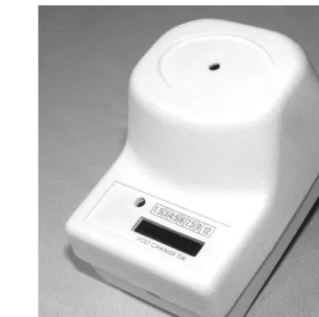
Now, where do you hide the beast? Well, since this unit emits hard-to-locate high frequencies, your options are endless. The high-pitched sound will exit through the smallest hole in whatever box you place the parts into. I decided to cram the works into an old wall adapter that has all of the guts removed, including any connection to the AC lines. The little speaker fits nicely into the top of the box, and there was just enough room for the 9-volt battery and small circuit board. Figure 2-8 shows the completed circuit going into the wall wart box.
There was just enough room to get all the parts inside, so I could not install an on-off switch, but
that was OK since the top of the box simply snapped together and I could simply unclip the battery. The unit will run for many days on a full battery, and if you strategically place the beeper, it may take that long for the unsuspecting victim to find it! If you plan to use a wall wart cabinet for the device like I did, ensure that there is no connection between the plug prongs and the AC lines. It is a good idea to remove them completely. Some other good hiding places might be a pop can, lunch box, wall clock, tissue box, or you could even install it into a working appliance. A solid cabinet will need a small hole for the speaker to optimize the distance that the sound will travel. I found that a quarter-inch hole was large enough for the tiny two-inch speaker I used. As I mentioned earlier, you can also use a piezo buzzer instead of a speaker, which would make the unit even smaller and possibly louder owing to the very good high-pitched operation of the piezo element. To use a piezo buzzer in place of the speaker, connect resistor R4 (which used to connect to one of the speaker terminals) directly to the +9 line, where the other speaker terminal used to connect.
[image:38.603.126.427.37.300.2]Project 2—Evasive Beeping Thing
This interesting project combines a little hardware with some timing electronics to simulate the sound of someone knocking on a door or wall. To create a circuit that sounds like three or four quick knocks, a 555 timer is used as a long delay counter set to stay off for a few minutes and then send out a pulse for about three seconds. This three-second pulse is not much use by itself, so it is fed into a PNP transistor in order to switch on a double-pole, double-throw relay, which is configured in such a way that it turns itself on and off several times per second. The other relay pole is then used to bang a washing machine or photocopier solenoid plunger up and down against the enclosure or wall to simulate the sound of rapping at the door. The operation of the timing hardware will be explained in more detail later, so dig into your scrap bin or
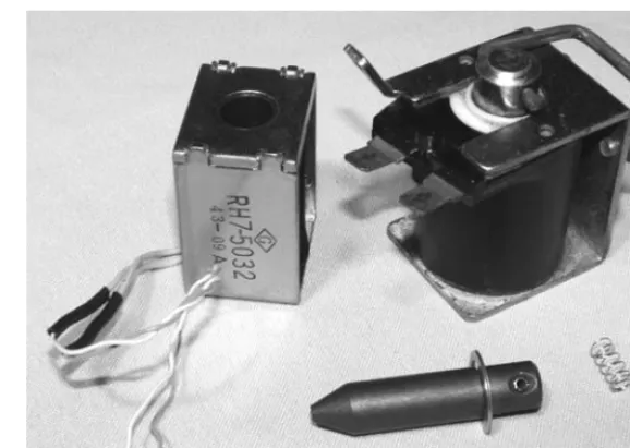
head down to the surplus electronics store and try to find a 5- or 12-volt mechanical solenoid like the ones shown in Figure 2-10.
A mechanical solenoid is nothing more than an electromagnet with a steel plunger placed in the center of the coil so that, when energized, the plunger will pull itself into the coil as far as it can go. Figure 2-10 shows a pair of solenoids taken
from a photocopier and a washing machine with one of the plungers removed from the
electromagnet. The solenoid on the left is rated for 12 volts, and the one on the right is rated for 24 volts, but they can both pull the plunger into the hole when the electromagnet is connected to a single 9-volt battery. At 24 volts, the larger solenoid will snap the plunger into position with great speed
Project 3—Ghost Door Knocker
Now you can place the piezo buzzer in parallel with R4 to make it function. The reason this is done is because the piezo element will offer very high resistance as compared to the very low resistance of the speaker, and the current from the battery needs to flow to transistor Q2’s collector.
The final product shown in Figure 2-9 looks at home just about anywhere there is a wall socket, and can be easily hidden under furniture or inside another appliance for truly covert mind-warping annoying fun and games. I have covered up the voltage switch from the original wall wart with black tape, and the little hole on the top of the case is barely large enough to pass a decent amount of high-pitched sound. With the component values given, the beep emits about once every three minutes and lasts for approximately five seconds, just enough time to entice the victim to look for the source of the sound before it goes silent. I like to drop the unit in a room, then claim that I can’t hear any beeping. This really gets the “beeper hunter” ticked off, and they try even harder to track down the evasive beeping thing to no avail.
[image:39.603.288.517.37.264.2]“I don’t hear anything pal, maybe you need an ear exam, or you should stop listening to pirated music on your MP3 player. I heard that the new copy protection can make your ears ring for days!”
Figure 2-9 What is that annoying beeping sound?
and force, but since we only want to lift the plunger about a quarter inch and then drop it, a 9-volt battery will certainly do the job. I even have a solenoid rated for 120 volts AC that works fine with the 9-volt battery. Solenoids will operate on both DC and AC, so often they are simply rated in voltage, and will range in size from about the size of a marker lid, to as large as a pop can. Do not worry about the voltage and size of the solenoid, just make sure that the plunger can lift its own weight when it is placed on a table and connected to a fresh 9-volt battery. The larger the plunger, the louder the noise it will make when released, so keep this in mind if you have a few options to choose from. Your solenoid may also come with a plunger stopper or some type of linkage connected to the end of the plunger. You can remove all of this unnecessary hardware in order to allow the basic plunger to come free from the hole in the electromagnet’s center.
If your plunger travels into the hole when energized by the 9-volt battery, it may fail to drop when the power is released due to friction or residual magnetism from the DC power source. This can be remedied as shown in Figure 2-11 by using a small piece of spring cut from a ballpoint pen, or even a tiny piece of sponge.
As shown in Figure 2-11, a bit of a ballpoint pen spring is cut and glued to the tip of the plunger to
help release it from the electromagnet once the battery is removed. You should be able to hold the solenoid upside down so that the plunger falls on to your workbench about a quarter inch out of the electromagnet hole, then pick it back up by energizing the electromagnet with a 9-volt battery. If your return spring is working, the plunger will then bang to the desk as soon as the power is removed from the electromagnet, which is the basis for our door-knocking sound. A little oil on the plunger may also help release it if it seems to stick in place randomly once pulled in by the electromagnet. When you get your solenoid working as described, bolt it into some type of enclosure so that the plunger
Project 3—Ghost Door Knocker
[image:40.603.133.422.36.241.2]Figure 2-10 Mechanical solenoids
is going on, but by then you will have had your fun, and pretending that you heard nothing makes it even more funny.
The timing cycle is taken from pin 3 of the 555 and fed into the base of PNP transistor Q1 in order to trigger the relays electromagnetic coil. Once the relay is engaged, it instantly charges capacitor C2, and at the same time disconnects itself from the transistor since the normally closed contacts are now open. Because the capacitor is charged first, the relay stays engaged for a few hundred milliseconds before the cycle repeats (as long as the 555 is saturating the base of Q1). The other pole of the relay is connected in reverse, so that each time the relay is engaged, power is sent into the solenoid’s electromagnetic coil, and this is the magic that creates the ‘knock, knock, knock’ sound. Back in the days when cars had no electronics, this is how a signal light flasher worked; using a relay and capacitor wired up just like our mechanical oscillator. If you want to play around with the speed of the knocking, simply try different values for the 4700µF capacitor, C2. Depending on how much current it takes your relay coil to energize, the 4700µF capacitor may give you a few knocks per second, or less than one. You will have to experiment a little here, but you are aiming for a knocking repetition that sounds like someone rapping at the door. If you cannot find large value capacitors, just install several in parallel and add their values together to create a larger capacitor with a longer relay holding time. Two 4700µF capacitors will create a 9400µF capacitor, and this will really slow down the knocking repetition. While
experimenting with the relay oscillation cycle, just remove the 1K resistor, R3 from the 555 pin, and place it to ground, rather than wait a minute for each timing cycle, and the relay will be constantly activated.
Figure 2-14 shows the completed circuit board tested and ready for installation. Notice the massive size of the 4700µF capacitor, C2; the larger the value, the larger the capacitor will
Project 3—Ghost Door Knocker
Figure 2-12 Solenoid installed
will be lifted about a quarter inch into the electromagnet, and then drop against the bottom of the enclosure.
Figure 2-12 shows my solenoid mounted inside a PVC box from a hardware store. There will be plenty of room inside the box for a small circuit board and the battery, and the thick plastic makes a good knock when the plunger bangs against it. If your solenoid is very strong using the 9-volt battery, then you may even consider adding a bolt or steel weight to the end of the plunger to further enhance the sound, but do make sure the plunger works reliably all the time. Now, let’s build the two-stage timer circuit, and start messing with your friends’ sanity.
Project 3—Ghost Door Knocker
C1: 100 µF C2: 4700 µF RY: DPDT relay Q1: 2N3906 NPN
D1: 1N4001 D2: 1N4001
R1: 1M R2: 10K R3: 1K 555 timer
R1
+9 V
R2
R3
NC NC
NO NO
Solenoid Q1
C1
C2
Gnd Gnd
+
+ D1
[image:42.603.128.434.41.349.2]D2 RY
Figure 2-13 Ghost door knocker schematic
[image:42.603.114.441.383.685.2]