PREFACE
1 BINARY SYSTEMS 1-1
1-2 1-3 1-4 1-5 1-6 1-7 1-8 1-9
Digital Computers and Digital Systems Binary Numbers 4
Number Base Conversions 6 Octal and Hexadecimal Numbers 9 Complements 10
Signed Binary Numbers 14 Binary Codes 17
Binary Storage and Registers 25 Binary Logic 28
References 32 Problems 33
1
2 BOOLEAN ALGEBRA AND LOGIC GATES 2-1
2-2
2-3
Basic Definitions
36
Axiomatic Definition of Boolean Algebra 38 Basic Theorems and Properties of Boolean Algebra
ix
1
36
41
iv Contents
2-4 2-5
Boolean Functions 45 Canonical and Standard FOnTIS 2-6 Other Logic Operations 56 2-7 Digital Logic Gates 58 2-8 Integrated Circuits 62
References 69 Problems 69
49
3 SIMPLIFICATION OF BOOLEAN FUNCTIONS
3-1 The Map Method 72
3-2 Two- and Three-Variable Maps 73 3-3 Four-Variable Map 78
3-4 Five-Variable Map 82
3-5 Product of Sums Simplification 84 3-6 NAND and NOR Implementation 88 3-7 Other Two-Level Implementations 94 3-8 Don't-Care Conditions 98
3-9 The Tabulation Method 101
3-10 Determination of Prime Implicants 101 3-11 Selection of Prime Implicants 106 3-12 Concluding Remarks 108
References 110 Problems III
4 COMBINATIONAL LOGIC
4-1 Introduction 114 4-2 Design Procedure 115
4-3 Adders 116
4-4 Subtractors 121 4-5 Code Conversion
124
4-6 Analysis Procedure 126 4-7 Multilevel NAND Circuits 1304-8 Multilevel NOR Circuits 138
72
Contents V
4-9 Exclusive-OR Functions 142 References 148
Problems 149
5
MSI AND PLD COMPONENTS
1525-1 Introduction 152
5-2 Binary Adder and Subtractor 154 5-3 Decimal Adder 160
5-4 Magnitude Comparator 163 5-5 Decoders and Encoders 166 5-6 Multiplexers 173
5-7 Read-Only Memory (ROM) 180 5-8 Programmable Logic Array (PLA) 187 5-9 Programmable Array Logic (PAL) 192
References 197 Problems 197
6 SYNCHRONOUS SEOUENTIAL LOGIC
202
6-1 Introduction 202
6-2 Hip-Hops 204
6-3 Triggering of Hip-Flops 210
6-4 Analysis of Clocked Sequential Circuits 218 6-5 State Reduction and Assignment 228 6-6 Hip-Flop Excitation Tables 231 6-7 Design Procedure 236
6-8 Design of Counters 247 References 251
Problems 251
7 REGISTERS, COUNTERS, AND THE MEMORY UNIT
257vi Contents
7-3 Shift Registers 264 7-4 Ripple Counters 272 7-5
7-6 7-7 7-8 7-9
Synchronous Counters 277 Timing Sequences 285 Random-Access Memory (RAM) Memory Decoding 293 Error -Correcting Codes References
302
Problems303
299
8 ALGORITHMIC STATE MACHINES IASMI 8-1 Introduction
307
8-2 ASM Chart
309
8-3 Timing Considerations 312 8-4 Control Implementation 317 8-5 Design with Multiplexers 323 8-6 PLA Control
330
References 336 Problems 337
9 ASYNCHRONOUS SEQUENTIAL LOGIC
9-1 Introduction 341 9-2 Analysis Procedure 343 9-3 Circuits with Latches 352 9-4 Design Procedure 359
9-5 Reduction of State and Flow Tables 9-6 Race-Free State Assignment 374
9-7 Hazards 379
9-8 Design Example 385 References 391 Problems 392
289
307
341
10 DIGITAL INTEGRATED CIRCUITS
10-1 Introduction 399
10-2 Special Characteristics 401 10-3
10-4 10-5 10-6 10-7 10-8
Bipolar-Transistor Characteristics 406 RTL and DTL Circuits 409
Transistor-Transistor Logic (TTL) Emmitter-Coupled Logic (ECL) Metal-Oxide Semiconductor (MOS)
412 422
424 Complementary MOS (CMOS) 427 10-9 CMOS Transmission Gate Circuits 430
References 433 Problems 434
11
LABORATORY EXPERIMENTS
11-0 Introduction to Experiments 436 11-1
11-2 11-3 11-4
Binary and Decimal Numbers 441 Digital Logic Gates 444
Simplification of Boolean Functions Combinational Circuits 447 11-5 Code Converters 449
11-6 Design with Multiplexers 451 11-7 Adders and Subtractors 452 11-8 Flip-Flops 455
11-9 Sequential Circuits 458 11-10 Counters 459
11-11 Shift Registers 461 11-12 Serial Addition 464 11-13 Memory Unit 465 11-14 Lamp Handball 467 11-15 Clock-Pulse Generator 471 11-16 Parallel Adder 473
11-17 11-18
Binary Multiplier 475 Asynchronous Sequential Circuits
446
477
Contents vii
399
436
viii Contents
12 STANDARD GRAPHIC SYMBOLS
12-1 Rectangular-Shape Symbols 479 12-2 Qualifying Symbols 482
12-3 Dependency Notation 484
12-4 Symbols for Combinational Elements 486
12-5 Symbols for Flip-Flops 489 12-6 Symbols for Registers 491 12-7 Symbols for Counters 494 12-8 Symbol for RAM 496
References 497 Problems 497
APPENDIX: ANSWERS TO SELECTED PROBLEMS
INDEX
479
499
Digital Design is concerned with the design of digital electronic circuits. The subject is also known by other names such as logic design, digital logic, switching circuits, and digital systems. Digital circuits are employed in the design of systems such as digital computers, control systems, data communications, and many other applications that re-quire electronic digital hardware. This book presents the basic tools for the design of digital circuits and provides methods and procedures suitable for a variety of digital de-sign applications.
Many features of the second edition remain the same as those of the first edition. The material is still organized in the same manner. The first five chapters cover combi-national circuits. The next three chapters deal with synchronous clocked sequential cir-cuits. Asynchronous sequential circuits are introduced next. The last three chapters deal with various aspects of commercially available integrated circuits.
The second edition, however, offers several improvements over the first edition. Many sections have been rewritten to clarify the presentation. Chapters I through 7 and Chapter 10 have been revised by adding new up-to-date material and deleting ob-solete subjects. New problems have been formulated for the first seven chapters. These replace the problem set from the first edition. Three new experiments have been added in Chapter II. Chapter 12, a new chapter, presents the IEEE standard graphic symbols for logic elements.
The following is a brief description of the subjects that are covered in each chapter with an emphasis on the revisions that were made in the second edition.
Ix
\
X Preface
Chapter 1 presents the various binary systems suitable for representing information in digital systems. The binary number system is explained and binary codes are illus-trated. A new section has been added on signed binary numbers.
Chapter 2 introduces the basic postulates of Boolean algebra and shows the correla-tion between Boolean expressions and their corresponding logic diagrams. All possible logic operations for two variables are investigated and from that, the most useful logic gates used in the design of digital systems are determined. The characteristics of inte-grated circuit gates are mentioned in this chapter but a more detailed analysis of the electronic circuits of the gates is done in Chapter 11.
Chapter 3 covers the map and tabulation methods for simplifying Boolean expres-sions. The map method is also used to simplify digital circuits constructed with AND-OR, NAND, or NOR gates. All other possible two-level gate circuits are considered and their method of implementation is summarized in tabular form for easy reference.
Chapter 4 outlines the formal procedures for the analysis and design of combina-tional circuits. Some basic components used in the design of digital systems, such as adders and code converters, are introduced as design examples. The sections on multi-level NAND and NOR implementation have been revised to show a simpler procedure for converting AND-OR diagrams to NAND or NOR diagrams.
Chapter 5 presents various medium scale integration (MS!) circuits and pro-grammable logic device (PLD) components. Frequently used digital logic functions such as parallel adders and sub tractors, decoders, encoders, and multiplexers, are ex-plained, and their use in the design of combinational circuits is illustrated with exam-ples. In addition to the programmable read only memory (PROM) and programmable logic array (PLA) the book now shows the internal construction of the programmable array logic (PAL). These three PLD components are extensively used in the design and implementation of complex digital circuits.
Chapter 6 outlines the formal procedures for the analysis and design of clocked syn-chronous sequential circuits. The gate structure of several types of flip-flops is pre-sented together with a discussion on the difference between pulse level and pulse tran-sition triggering. Specific examples are used to show the derivation of the state table and state diagram when analyzing a sequential circuit. A number of design examples are presented with added emphasis on sequential circuits that use D-type flip-flops.
Chapter 7 presents various sequential digital components such as registers, shift registers, and counters. These digital components are the basic building blocks from which more complex digital systems are constructed. The sections on the random ac-cess memory (RAM) have been completely revised and a new section deals with the Hamming error correcting code.
Chapter 8 presents the algorithmic state machine (ASM) method of digital design. The ASM chart is a special flow chart suitable for describing both sequential and paral-lel operations with digital hardware. A number of design examples demonstrate the use of the ASM chart in the design of state machines.
cir-Preface xl
cuit can be implemented as a combinational circuit with feedback. An alternate imple-mentation is also described that uses SR latches as the storage elements in an asyn-chronous sequential circuit.
Chapter 10 presents the most common integrated circuit digital logic families. The electronic circuits of the common gate in each faruily is analyzed using electrical circuit theory. A basic knowledge of electronic circuits is necessary to fully understand the material in this chapter. Two new sections are induded in the second edition. One sec-tion shows how to evaluate the numerical values of four electrical characteristics of a gate. The other section introduces the CMOS transmission gate and gives a few exam-ples of its usefulness in the construction of digital circuits.
Chapter 11 outlines 18 experiments that can be performed in the laboratory with hardware that is readily and inexpensively available commercially. These experiments use standard integrated circuits of the TTL type. The operation of the integrated cir-cuits is explained by referring to diagrams in previous chapters where siruilar compo-nents are originally introduced. Each experiment is presented informally rather than in a step-by-step fashion so that the student is expected to produce the details of the cir-cuit diagram and formulate a procedure for checking the operation of the circir-cuit in the laboratory.
Chapter 12 presents the standard graphic symbols for logic functions recommended by ANSI/IEEE standard 91-1984. These graphic symbols have been developed for SSI and MSI components so that the user can recognize each function from the unique graphic symbol assigned to it. The best time to learn the standard symbols is while learning about digital systems. Chapter 12 shows the standard graphic symbols of all the integrated circuits used in the laboratory experiments of Chapter 11.
The various digital componets that are represented throughout the book are similar to commercial MSI circuits. However. the text does not mention specific integrated cir-cuits except in Chapters 11 and 12. The practical application of digital design will be enhanced by doing the suggested experiments in Chapter 11 while studying the theory presented in the text.
Each chapter in the book has a list of references and a set of problems. Answers to most of the problems appear in the Appendix to aid the student and to help the inde-pendent reader. A solutions manual is available for the instructor from the publisher.
M. Morris Mano
Binary'
$ystems
1·1 DIGITAL COMPUTERS AND DIGITAL SYSTEMS
Digital computers have made possible many scientific, industrial, and commercial ad-vances that would have been unattainable otherwise. Our space program would have been impossible without real-time, continuous computer monitoring, and many busi-ness enterprises function efficiently only with the aid of automatic data processing. Computers are used in scientific calculations, commercial and business data processing, air traffic control, space guidance, the educational field, and many other areas. The most striking property of a digital computer is its generality. It can follow a sequence of instructions, called a program, that operates on given data. The user can specify and change programs and/or data according to the specific need. As a result of this flexibility, general-purpose digital computers can perform a wide variety of informa-tion-processing tasks.
The general-purpose digital computer is the best-known example of a digital system. Other examples include telephone switching exchanges, digital voltmeters, digital counters, electronic calculators, and digital displays. Characteristic of a digitaLsYstem is its manipulation. of discrete elements of information: SlicIi(JJscreteeiemenis may
be .
electric impulses, th;;-decimaf <iigTiS:-tlie letters of an alphabet, arithmetic operations,punctuation marks, or any other set of meaningful symbols. The juxtaposition of dis-crete elements of information represents a quantity of information. For example, the letters d, 0, and g form the word dog. The digits 237 form a number. Thus, a sequence of discrete elements forms a language, that is, a discipline that conveys information. Early digital computers were used mostly for numerical computations. In this case, the
2 Chapter 1 Binary Systems
discrete elements used are the digits. From this application, the term digital computer has emerged. A more appropriate name for a digital computer would be a "discrete in-formation-processing system."
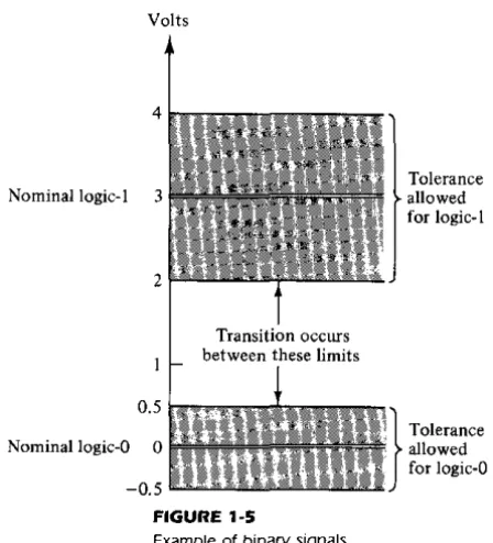
Discrete elements of information are represented in a digital system by physical quantities called signals. Electrical signals such as voltages and currents are the most common. The signals in all present-day electronic digital systems have only two dis-crete values and are said to be binary. The digital-system designer is restricted to the use of binary signals because of the lower reliability of many-valued electronic circuits. In other words, a circuit with ten states, using one discrete voltage value for each state, can be designed, but it would possess a very low reliability of operation. In contrast, a transistor circuit that is either on or off has two possible signal values and can be con-structed to be extremely reliable. Because of this physical restriction of components, and because human logic tends to be binary, digital systems that are constrained to take discrete values are further constrained to take binary values.
Discrete quantities of information arise either from the nature of the process or may be quantized from a continuous process. For example, a payroll schedule is an inher-ently discrete process that contains employee names, social security numbers, weekly salaries, income taxes, etc. An employee's paycheck is processed using discrete data values such as letters of the alphabet (names), digits (salary), and special symbols such as $. On the other hand, a research scientist may observe a continuous process but record only specific quantities in tabular form. The scientist is thus quantizing his con-tinuous data. Each number in his table is a discrete element of information.
Many physical systems can be described mathematically by differential equations whose solutions as a function of time give the complete mathematical behavior of the process. An analog computer performs a direct simulation of a physical system. Each section of the computer is the analog of some particular portion of the process under study. The variables in the analog computer are represented by continuous signals, usu-ally electric voltages that vary with time. The signal variables are considered analogous to those of the process and behave in the same manner. Thus, measurements of the analog voltage can be substituted for variables of the process: The term analog signal is sometimes substituted for continuous signal because "analog computer" has come to mean a _computer that manipulates continuous variables.
To simulate a physical process in a digital computer, the quantities must be quan-tized. When the variables of the process are presented by real-time continuous signals, the latter are quantized by an analog-to-digital conversion device. A physical system whose behavior is described by mathematical equations is simulated in a digital com-puter by means of numerical methods. When the problem to be processed is inherently discrete, as in commercial applications, the digital computer manipulates the variables in their natural form.
Section 1 ~ 1 Digital Computers and Digital Systems 3
Control Processor,
unit or
arithmetic unit
Storage, or memory unit
Input Output
devices devices and control and control
FIGURE 1·1
Block diagram of a digital computer
each instruction, the control unit informs the processor to execute the operation specified by the instruction. Both program and data are stored in memory. The control unit supervises the program instructions, and the processor manipulates the data as specified by the program.
The program and data prepared by the user are transferred into the memory unit by means of an input device such as a keyboard. An output device, such as a printer, re-ceives the result of the computations and the printed results are presented to the user. The input and output devices are special digital systems driven by electromechanical parts and controlled by electronic digital circuits.
An electronic calculator is a digital system similar to a digital computer, with the in-put device being a keyboard and the outin-put device a numerical display. Instructions are entered in the calculator by means of the function keys, such as plus and minus. Data are entered through the numeric keys. Results are displayed directly in numeric form. Some calculators come close to resembling a digital computer by having printing capa-bilities and programmable facilities. A digital computer, however, is a more powerful device than a calculator. A digital compiIter can accommodate many other input and output devices; it can perform not only arithmetic computations, but logical operations as well and can be programmed to make decisions based on internal and external con-ditions.
4 Chapter 1 Binary Systems
The operational characteristics of the memory unit are explained at the end of Chapter 7. The design of the control unit is discussed in Chapter 8 using the basic principles of sequential circuits from Chapter 6.
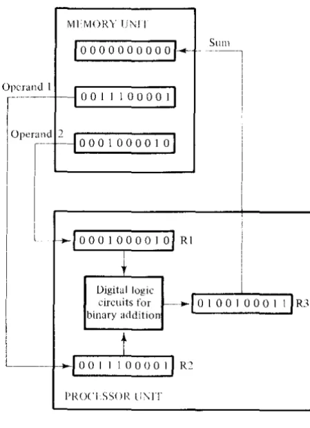
It has already been mentioned that a digital computer manipulates discrete elements of information and that these elements are represented in the binary form. Operands used for calculations may be expressed in the binary number system. Other discrete ele-ments, including the decimal digits, are represented in binary codes. Data processing is carried out by means of binary logic elements using binary signals. Quantities are stored in binary storage elements. The purpose of this chapter is to introduce the vari-ous binary concepts as a frame of reference for further detailed study in the succeeding chapters.
1-2 BINARY NUMBERS
A decimal number such as 7392 represents a quantity equal to 7 thousands plus 3 hun-dreds, plus 9 tens, plus 2 units. The thousands, hunhun-dreds, etc. are powers of 10 implied by the position of the coefficients. To be more exact, 7392 should be written as
7 X 10³
+
3 X 10²+
9 X 10'+
2 x 10°However, the convention is to write only the coefficients and from their position de-duce the necessary powers of 10. In general, a number with a decimal point is repre-sented by a series of coefficients as follows:
The aj coefficients are one of the ten digits (0, 1,2, . . . ,9), and the subscript valuej
gives the place value and, hence, the power of 10 by which the coefficient must be mul-tiplied.
10'a,
+
104a4+
103a3+
102a2+
lOla,+
100ao+
1O-'a_,+
1O- 2a_2+
1O-3a_3 The decimal number system is said to be of base, or radix, 10 because it uses ten digits and the coefficients are multiplied by powers of 10. The binary system is a different number system. The coefficients of the binary numbers system have two possible val-ues: 0 and 1. Each coefficient aj is multiplied by 21. For example, the decimalequiva-lent of the binary number 11010.11 is 26.75, as shown from the multiplication of the coefficients by powers of 2:
I X 24
+
I X 23+
0 X 22+
1 X 2'+
0 x 2°+
I x 2 -,+
1 X 2- 2 = 26.75In general, a number expressed in base-r system has coefficients multiplied by powers of r:
an'r"
+
a,,_1'r,,--'1+ ' , '
+ a2'r 2
+
aj'r+
GoSection 1-2 Binary Numbers 5 The coefficientsaj rangein vllJue Jrom 0 to r - 1. To distinguish between numbers of different bases, we enclose the coefficients in parentheses and write a subscript equal to the base used (except sometimes for decimal numbers, where the content makes it ob-vious that it is decimal). An example of a base-5 number is
(4021.2)5 = 4 X 53
+
0 X 5'+
2 X 5'+
1 X 50+
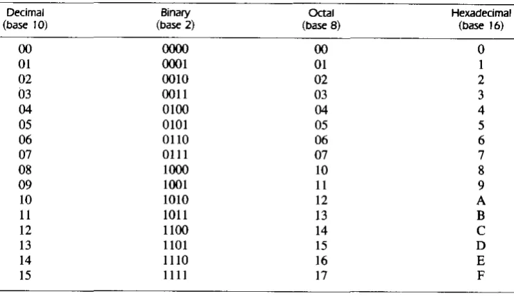
2 X 5-' = (511.4ho Note that coefficient values for base 5 can be only 0, I, 2, 3, and 4.It is customary to borrow the needed r digits for the coefficients from the decimal system when the base of the number is less than 10. The letters of the alphabet are used to supplement the ten decimal digits when the base of the number is greater than 10. For example, in the hexadecimal (base 16) number system, the first ten digits are bor-rowed from the decimal system. The letters A, B, C, D, E, and F are used for digits
10, 11, 12, 13, 14, and 15, respectively. An example of a hexadecimal number is
(B 65Fh. = 11 X 163
+
6 X 16'+
5 X 16+
15 = (46687)10The first 16 numbers in the decimal, binary, octal, and hexadecimal systems are listed in Table I-I.
TABLE ,-,
Numbers with Different Bases
Decimal Binary OCtal Hexadecimal
(base 10) (base 2) (base B) (base 16)
00 ()()()() 00 0
01 0001 01 I
02 0010 02 2
03 0011 03 3
04 0100 04 4
05 0101 05 5
06 0110 06 6
07 0111 07 7
08 1000 10 8
09 1001 11 9
10 1010 12 A
II 1011 13 B
12 1100 14 C
13 1101 15 D
14 1110 16 E
15 1111 17 F
[image:14.544.117.487.301.514.2]6 Chapter 1 Binary Systems
augend: 101101 minuend: addend:
+
100111 subtrahend: sum: 1010100 difference:101101 -100111 000110
multiplicand: multiplier:
product:
1011 x 101 1011 0000 1011 110111
The sum of two binary numbers is calculated by the same rules as in decimal, except that the digits of the sum in any significant position can be only 0 or I. Any carry ob-tained in a given significant position is used by the pair of digits one significant position higher. The subtraction is slightly more complicated. The rules are still the same as in decimal, except that the borrow in a given significant position adds 2 to a minuend digit. (A borrow in the decimal system adds 10 to a minuend digit.) Multiplication is very simple. The multiplier digits are always I or O. Therefore, the partial products are equal either to the multiplicand or to O.
1-3 NUMBER BASE CONVERSIONS
Example
1-1
A binary number can be converted to decimal by forming the sum of the powers of 2 of those coefficients whose value is 1. For example
(1010.011), ~ 2'
+
21+
2 '+
2-1 ~ (10.375)10The binary !lumber has four I's and the decimal equivalent is found from the sum of four powers of 2. Similarly, a number expressed in base r can be converted to its deci-mal equivalent by mUltiplying each coefficient with the corresponding power of rand adding. The following is an example of octal-to-decimal conversion:
(630.4h ~ 6 X 82
+
3 X 8+
4 X 8-1 ~ (408.5)10The conversion from decimal to binary or to any other base-r system is more
con-venient if the number is separated into an integer part and a fraction part and the conversion of each part done separately. The conversion of an integer from decimal to binary is best explained by example.
Example 1-2
Section 1-3 Number Base Conversions
Integer
quotient Remainder Coefftclent
41
20
+
I ao=
I2 2
20
10
+
0 a,=
02 10
5
+
0 a2=
02=
5
2
+
I a,=
I2:=
22
I
+
0 a4=
02:=
I
0
+
I as = 1=
2 2
answer: (41)10
=
(a,a4a,a2a,ao)'=
(101001),The arithmetic process can be manipulated more conveniently as follows:
Integer
41 20 10 5
2
I
o
Remainder
7
•
The conversion from decimal integers to any base-r system is similar to the exam-ple, except that division is done by r instead of 2.
Convert decimal 153 to octal. The required base r is 8. First, 153 is divided by 8 to give an integer quotient of 19 and a remainder of I. Then 19 is divided by 8 to give an integer quotient of 2 and a remainder of 3. Finally, 2 is divided by 8 to give a quotient of 0 and a remainder of 2. This process can be conveniently manipulated as follows:
153 19 I
2 3
8 Chapter 1 Binary Systems
Example 1-3
Example 1-4
The conversion of a decimal fraction to binary is accomplished by a method similar to that used for integers. However, multiplication is used instead of division, and in-tegers arc accumulated instead of remainders. Again, the method is best explained by example.
Convert (0.6875)10 to binary. First, 0.6875 is multiplied by 2 to give an integer and a fraction. The new fraction is multiplied by 2 to give a new integer and a new fraction. This process is continued until the fraction becomes 0 or until the number of digits have sufficient accuracy. The coefficients of the binary number are obtained from the integers as follows:
Integer Fraction Coefficient
0.6875 x 2 = 1
+
0.3750 a-I = 10.3750 x 2 = 0
+
0.7500 U-2 = 00.7500 X 2 =
+
0.5000 a-3 =0.5000 X 2 =
+
0.0000 a-4 =Answer: (0.6875)'0 = (O.a la-2u-3 a
-4h
= (O.lDII),•
To conyert a decimal fraction to a number expressed in base r, a similar procedure is used. Multiplication is by r instead of 2, and the coefficients found from the integers may range in value from 0 to r - I instead of 0 and I.
Convert (0.513)10 to octal.
0.513 x 8 = 4.104 0.104 X 8 = 0.832 0.832 x 8 = 6.656 0.656 x 8 = 5.248 0.248 x 8 = 1.984 0.984 x 8 = 7.872
The answer, to seven significant figures, is obtained from the integer part of the prod-ucts:
(0.513),0 = (0.406517 ...
ls
•
Section 1 ~4 Octal and Hexadecimal Numbers 9
(41.6875)10
=
(101001.10I1h From Examples 1-2 and 1-4, we have(153.513)10 = (231.406517),
1-4 OCTAl. AND HEXADECIMAl. NUMBERS
The conversion from and to binary, octal, and hexadecimal plays an important part in digital computers. Since 23
=
8 and 24
=
16, each octal digit corresponds to three bi-nary digits and each hexadecimal digit corresponds to four bibi-nary digits. The conver-sion from binary to octal is easily accomplished by partitioning the binary number into groups of three digits each, starting from the binary point and proceeding to the left and to the right. The corresponding octal digit is then assigned to each group. The fol-lowing example illustrates the procedure:(10 110 001 101 011 111 100 000 110 h = (26153.7460),
L.J L-...J L-...J L-...J L-...J L-...J L-...J L-....J L-...J
2 6 5 3 7 4 0 6
Conversion from binary to hexadecimal is similar, except that the binary number is di-vided into groups of four digits:
(10 1100 0110 1011 1111 0010 h
=
(2C6B.F2h.L.J L---....J L---....J L---....J l..-...J l..-...J
2 C 6 B F 2
The corresponding hexadecimal (or octal) digit for each group of binary digits is easily remembered after studying the values listed in Table 1-1.
Conversion from octal or hexadecimal to binary is done by a procedure reverse to the above. Each octal digit is converted to its three-digit binary equivalent. Similarly, each hexadecimal digit is converted to its four-digit binary equivalent. This is illus-trated in the following examples:
(673.124),
= (
110 111 011 001 010 100 h' - - J ' - - J ' - - J ' - - J ' - - J ' - - J
6 7 3 1 2 4
(306.Dh.
= (
0011 0000 0110 1101h
l..-...J l..-...J '---' l..-...J3 0 6 D
1 0 Chapter 1 Binary Systems
utilizes the relationship between the binary number system and the octal or hexadeci-mal system. By this method, the human thinks in terms of octal or hexadecihexadeci-mal num-bers and performs the required conversion by inspection when direct communication with the machine is necessary. Thus the binary number 111111111111 has 12 digits and is expressed in octal as 7777 (four digits) or in hexadecimal as FFF (three digits). During communication between people (about binary numbers in the computer), the octal or hexadecimal representation is more desirable because it can be expressed more compactly with a third or a quarter of the number of digits required for the equivalent binary number. When the human communicates with the machine (through console switches or indicator lights or by means of programs written in machine language), the conversion from octal or hexadecimal to binary and vice versa is done by inspection by the human user.
1-5 COMPLEMENTS
Complements are used in digital computers for simplifying the subtraction operation and for logical manipulation. There are two types of complements for each base-r sys-tem: the radix complement and the diminished radix complement. The first is referred to as the r's complement and the second as the (r - I)'s complement. When the value of the base r is substituted in the name, the two types are referred to as the 2's comple-ment and l's complecomple-ment for binary numbers, and the 10's complecomple-ment and 9's com-plement for decimal numbers.
Diminished Radix Complement
Given a number N in base r having n digits, the (r - l)'s complement of N is defined as (r" - 1) - N. For decimal numbers, r = 10 and r - 1 = 9, so the 9's comple-ment of N is (10" - 1) - N. Now, 10" represents a number that consists of a single 1 followed by nO's. 10" - I is a number represented by n 9's. For example, if n = 4, we have 104 =
10,000 and 104
- 1 = 9999. It follows that the 9's complement of a decimal number is obtained by subtracting each digit from 9. Some numerical examples follow.
The 9's complement of 546700 is 999999 - 546700 = 453299. The 9's complement of 012398 is 999999 - 012398
=
987601.Section 1-5 Complements 11
the bit to change from 0 to I or from I to O. Therefore, the I's complement of a binary number is formed by changing I's to O's and O's to I's. The following are some
nu-merical examples.
-The I's complement of 1011000 is 0100111. The I's complement of 0101101 is 1010010.
The (r - I)'s complement of octal or hexadecimal numbers is obtained by subtracting each digit from
'7
or F (decimal 15), respecti"ely.Radix Complement
The r's complement of an n-digit number,N in.J?llse r is defined as r" -
!!fOLN,"i:))_
and 0 for N = O. Comparing with the (r - I)'s complement, we note that the r's coriipremefitTs06talned--by adding I to the (r - I)'s complement since r" - N
=
'[(r" - I) -
NJ
+
1. Thus, the lO's complement of decimal 2389 is 7610+
I = 7611 and is obtained by adding I to the 9's-complement value. The 2's complement of bi-nary 101100 is 010011+
I = 010100 and is obtained by adding I to theI's-comple-ment value. . .
-Since 10" is a number represented by a I followed by nO's, 10" - N, which is the lO's complement of N, can be formed also by leaving all least significant O's un-changed, subtracting the first nonzero least significant digit from 10, and subtracting all higher significant digits from 9.
The lO's complement of 012398 is 987602. The lO's complement of 246700 is 753300.
The lO's complement of the first number is obtained by subtracting 8 from 10 in the least significant position and subtracting all other digits from 9. The lO's complement of the second number is obtained by leaving the two least significant O's unchanged, subtracting 7 from 10, and subtracting the other three digits from 9.
Similarly, the 2's complement can be formed by leaving all least significant O's and the first I unchanged, and replacing I's with O's and O's with I's in all other higher significant digits.
The 2's complement of 1101100 is 0010100. The 2's complement of 0110111 is 1001001.
12 Chapter 1 Binary Systems
temporarily in order to form the r's or (r ~ I)'s complement. The radix point is then restored to the complemented number in the same relative position. It is also worth mentioning that the complement of the complement restores the number to its original value. The r's complement of N is r" ~ N. The complement of the complement is r" ~ (r" ~ N) = N, giving back the original number.
Subtraction with Complements
Example
1-5
The direct method of subtraction taught in elementary schools uses the borrow con-cept. In this method, we borrow a I from a higher significant position when the minu-end digit is smaller than the subtrahminu-end digit. This seems to be easiest when people per-form subtraction with paper and pencil. When subtraction is implemented with digital hardware, this method is found to be less efficient than the method that uses comple-ments.
The subtraction of two n-digit unsigned numbers M ~ N in base r can be done as follows:
1. Add the minuend M to the r's complement of the subtrahend N. This performs M
+
(r" ~ N) = M ~ N+
r".2. If M :2: N, the sum will produce an end carry, r", which is discarded; what is left is the result M ~ N.
3. If M < N, the sum does not produce an end carry and is equal to r" ~ (N ~ M), which is the r's complement of (N ~ M). To obtain the answer in a familiar form, take the r's complement of the sum and place a negative sign in front.
The folJowi[lg examples illustrate the procedure.
Using 10's complement, subtract 72532 ~ 3250.
M=
10' s complemen t of N =
Sum = Discard end carry 105 =
Answer =
72532
+
96750 169282~100000
69282
•
Note that M has 5 digits and N has only 4 digits. Both numbers must have the same number of digits; so we can write N as 03250. Taking the lO's complement of N pro-duces a 9 in the most significant position. The occurrence of the end carry signifies that
Example
1·6
Example 1·7
Section 1 ~5 Complements 13
Using lO's complement, subtract 3250 - 72532.
M=
10' s complement of N =
Sum =
There is no end carry.
03250
+
27468 30718Answer: -(10's complement of 30718) = -69282
•
Note that since 3250
<
72532, the result is negative. Since we are dealing with un-signed numbers, there is really no way to get an unun-signed result for this case. When subtracting with complements, the negative answer is recogniz..,d from the absence .of the end carry and the complem~nted result. When working with paper and pencil, we . can change the answer to'a -signed negative number in order to put it in a familiar form. Subtraction with complements is done with binary numbers in a similar manner us-ing the silIlle procedure outlined before.Given the two binary numbers X = 1010100 and Y = 1000011, perform the subtrac-tion (a) X - Yand (b) Y - X using2's complements.
(a)
(b)
X=
2's complement of Y =Sum =
Discard end carry 2' =
Answer: X - Y =
Y=
2's complement of X
=
Sum=
There is no end carry.1010100
+
0111101 10010001 -10000000 00100011000011
+
0101100 110111114 Chapter 1 Binary Systems
Example
1·8
Repeat Example 1-7 using I's complement. (a) X - Y = 1010100 - 1000011
X=
I's complement of Y =
Sum = End-around carry
Answer: X - Y
(b) Y - X = 1000011 - 1010100
y= I ' s complement of X =
Sum = There is no end carry.
1010100
+
0111100I
10010000~+1
0010001
1000011
+
0101011 1101110Answer: Y - X = -(1's complement of 1101110) = -0010001
Note that the negative result is obtained by taking the I's complement of the sum since this is the type of complement used. The procedure with end-around carry is also applicable for subtracting unsigned decimal numbers with 9's complement.
1·6 SIGNED BINARY NUMBERS
Positive integers including zero can be represented as unsigned numbers. However, to represent negative integers, we need a notation for negative values. In ordinary arith-metic, a negative number is indicated by a minus sign and a positive number by a plus sign. Because of hardware limitations, computers must represent everything with bi-nary digits, commonly referred to as bits. It is customary to represent the sign with a bit placed in the leftmost position of the number. The convention is to make the sign bit 0 for positive and I for negative.
neg-Section 1·6 Signed Binary Numbers 15
ative, and the other four bits, which represent binary 9. Usually, there is no confusion in identifying the bits if the type of representation for the number is known in advance. The representation of th" signed numbers in the la~t examjJle hueferred to as the signed-magnitude convention. In this notation, the number consists of a magnitude and a symbol (+ or -) or a bit (0 or I) indicating the sign. This is the representation of signed numbers used in ordinary arithmetic. When arithmetic operations are imple-mented in a computer, it is more convenient to use a different system for repreSenting negative numbers, referred to as the signed-complement system. In this system, a nega-tive number is indicated by its complement. Whereas the signed-magnitude system negates a number by changing its sign, the signed-complement system negates a number by taking its complement. Since positive numbers always start with 0 (plus) in the left-most position, the complement will always start with a I, indicating a negative number. The signed-complement system can use either the I's or the Z's complement, but the
Z's complement is the most common.
As an example, consider the number 9 represented in binary with eight bits. +9 is represented with a sign bit of 0 in the leftmost position followed by the binary equiva-lent of 9 to give 00001001. Note that all eight bits must have a value and, therefore, O's are inserted following the sign bit up to the first I. Although there is only one way to represent +9, there are three different ways to represent - 9 with eight bits:
In signed-magnitude representation: In signed-I's-complement representation: In signed-Z's-complement representation:
10001001 11110110 11110111
In signed-magnitude, -9 is obtained from +9 by changing the sign bit in the-leftmost position from 0 to
J._
In
signed-I's complement, -9j8 obtained by complementing all the bits of +9, including the sign bit. The signed-Z's-complement representatioll of -9 is obtained by taking the Z's complement of the positive number, including the sign bit.The signed-magnitude system is used in ordinary arithmetic, but is awkward when employed in computer arithmetic. Therefore, the signed-complement is normally used. The I's complement imposes some difficulties and is seldom used for arithmetic erations except in some older computers. The I's complement is useful as a logical op-eration since the change of J to 0 or 0 to 1 is equivalent to a logical complement operation, as will be shown in the next chapter. The following discussion of signed bi-nary arithmetic deals exclusively with the signed-Z's-complement representation of negative numbers. The same procedures can be applied to the signed-I's-complement system by including the end-around carry as done with unsigned numbers.
ArithmetIc AddItion
16 Chapter 1 Binary Systems
from the larger and give the result the sign of the larger magnitude. For example, (+25) + ( - 37)
=
-(37 - 25)=
-12 and is done by subtracting the smaller mag-nitude 25 from the larger magmag-nitude 37 and using the sign of 37 for the sign of the re-sult. This is a process that requires the comparison of the signs and the magnitudes and then performing either addition or subtraction. The same procedure applies to binary numbers in signed-magnitude representation. In contrast, the rule for adding numbers in the signed-complement system does not require a comparison or subtraction, but only addition. The procedure is very simple and can be stated as follows for binary numbers.The addition of two signed binary numbers with negative numbers represented in signed-2's-complement form is obtained from the addition of the two numbers, including their sign bits. A carry out of the sign-bit position is discarded.
Numerical examples for addition follow. Note that negative numbers must be initially in 2's complement and that the sum obtained after the addition if negative is in 2's-com-plement form.
+ 6 00000 I 1 0 - 6 11111010
+13 00001101 +13 00001101
+19 00010011 + 7 00000 I 1 I
+ 6 00000110 6 11111010
-13 11110011 -13 IlllOOl1
- 7 11111001 -19 11 101 101
In each of the four cases, the operation performed is addition with tbe ~ign bit included. Any carry out of the sign-bit pOSition is discarded, and negative results are automati-cally in 2's-complement form.
In order to obtain a correct answer, we must ensure that the result has a sufficient number of bits to accommodate the sum. If we start with two n-bit numbers and the sum occupies n + I bits, we say that an overflow occurs. When one performs the addi-tion with paper and pencil, an overflow is not a problem since we are not limited by the width of the page. We just add another 0 to a positive number and another I to a nega-tive number in the most-significant position to extend them to n + I bits and then per-form the addition. Overflow is a problem in computers because the number of bits that hold a number is finite, and a result that exceeds the finite value by I cannot be accom-modated.
Section 1·7 Binary Codes 17 Arithmetic Subtraction
Subtraction of two signed binary numbers when negative numbers are in 2's-comple-ment form is very simple and can be stated as follows:
Take the 2's complement of the subtrahend (including the sign bit) and add it to the minu-end (including the sign bit). A carry out of the sign-bit position is discarded.
This procedure occurs because a subtraction operation can be changed to an addition operation if the sign of the subtrahend is changed. This is demonstrated by the follow-ing relationship:
(±A) - (+B) = (±A) + (-B) (±A) - (-B) = (±A)
+
(+B)But changing a positive number to a negative number is easily done by taking its 2's complement. The reverse is also true because the complement of a negative number in complement form produces the equivalent positive number. Consider the subtraction of (-6) - (-13) = +7. In binary with eight bits, this is written as (11111010 -11110011). The subtraction is changed to addition by taking the 2's complement of the subtrahend (-13) to give (+13). In binary, this is 11 111010
+
00001101 =10000011 1. Removing the end carry, we obtain the correct answer 00000111 (+7).
It is worth noting that binary numbers in the signed-complement system are added and subtracted by the same basic addition and subtraction rules as unsigned numbers. Therefore, computers need only one common hardware circuit to handle both types of arithmetic. The user or programmer must interpret the results of such addition or sub-traction differently, depending on whether it is assumed that the numbers are signed or unsigned.
1-7 BINARY CODES
Electronic digital systems use signals that have two distinct values and circuit elements that have two stable states. There is a direct analogy among binary signals, binary cir-cuit elements, and binary digits. A binary number of n digits, for example, may be rep-resented by n binary circuit elements, each having an output signal equivalent to a 0 or a 1. Digital systems represent and manipulate not only binary numbers, but also many other discrete elements of information. Any discrete element of information distinct among a group of quantities can be represented by a binary code. Binary codes play an important role in digital computers. The codes must be in binary because computers can only hold I's and O's. It must be realized that binary codes merely change the sym-bols, not the meaning of the elements of information that they represent. If we inspect the bits of a computer at random, we will find that most of the time they represent some type of coded information rather than binary numbers.
A bit, by definition, is a binary digit. When used in conjunction with a binary code,
18 Chapter 1 Binary Systems
group of 2" distinct elements in a binary code requires a minimum of n bits. This is be-cause it is possible to arrange n bits in 2" distinct ways. For example, a group of four distinct quantities can be represented by a two-bit code, with each quantity assigned one of the following bit combinations: 00, 01, 10, 11. A group of eight elements re-quires a three-bit code, with each element assigned to one and only one of the follow-ing: 000, 001, 010, all, 100, 101, 110, 111. The examples show that the distinct bit combinations of an n-bit code can be found by counting in binary from a to (2" ~ I). Some bit combinations are unassigned when the number of elements of the group to be coded is not a mUltiple of the power of 2. The ten decimal digits 0, 1, 2, . . . , 9 are an example of such a group. A binary code that distinguishes among ten elements must contain at least four bits; three bits can distinguish a maximum of eight elements. Four bits can form 16 distinct combinations, but since only ten digits are coded, the remain-ing six combinations are unassigned and not used.
Although the minimum number of bits required to code 2" distinct quantities is n, there is no maximum number of bits that may be used for a binary code. For example, the ten decimal digits can be coded with ten bits, and each decimal digit assigned a bit combination of nine 0'5 and a I. In this particular binary code, the digit 6 is assigned the bit combination 0001000000.
Decimal Codes
Binary codes for decimal digits require a minimum of four bits. Numerous different codes can be obtained by arranging four or more bits in ten distinct possible combina-tions. A few possibilities are shown in Table 1-2.
TABLE 1-2
Binary codes for the decimal digits
.---~----. - - - ~--
-Decimal (BCD) (BiqUinary)
digit B421 Excess-3 B4-2-1 2421 5043210
- - -
-0 0000 0011 0000 0000 0100001
1 0001 0100 0111 0001 0100010
2 0010 0101 0110 0010 0100100
3 0011 0110 0101 0011 0101000
4 0100 0111 0100 0100 0110000
5 0101 1000 1011 1011 1000001
6 0110 1001 1010 1100 1000010
7 0111 1010 1001 1101 1000100
8 1000 1011 1000 1110 1001000
9 1001 1100 1111 1111 1010000
--- - - -
Section 1 _7 Binary Codes 19
I X 2
+
0 X I = 6. It is also possible to assign negative weights to a decimal code, as shown by the 8, 4, -2, -I code. In this case, the bit combination 0110 is inter-preted as the decimal digit 2, as obtained from 0 X 8+
I X 4+
I X (-2)+
0 X(-I) = 2. Two other weighted codes shown in the table are the 2421 and the 5043210. A decimal code that has been used in some old computers is the excess-3 code. This is an unweighted code; its code assignment is obtained from the corresponding value of BCD after the addition of 3.
Numbers are represented in digital computers either in binary or in decimal through a binary code. When specifying data, the user likes to give the data in decimal form. The input decimal numbers are stored internally in the computer by means of a decimal code. Each decimal digit requires at least four binary storage elements. The decimal numbers are converted to binary when arithmetic operations are done internally with numbers represented in binary. It is also possible to perform the arithmetic operations directly in decimal with all numbers left in a coded form throughout. For example, the decimal number 395, when converted to binary, is equal to 110001011 and consists of nine binary digits. The same number, when represented internally in the BCD code, occupies four bits for each decimal digit, for a total of 12 bits: 001110010101. The first four bits represent a 3, the next four a 9, and the last four a 5.
It is very important to understand the difference between conversion of a decimal number to binary and the binary coding of a decimal number. In each case, the final result is a series of bits. The bits obtained from conversion are binary digits. Bits ob-tained from coding are combinations of I's and O's arranged according to the rules of the code used. Therefore, it is extremely important to realize that a series of I's and O's in a digital system may sometimes represent a binary number and at other times repre-sent some other discrete quantity of information as specified by a given binary code. The BCD code, for example, has been chosen to be both a code and a direct binary conversion, as long as the decimal numbers are integers from 0 to 9. For numbers greater than 9, the conversion and the coding are completely different. This concept is so important that it is worth repeating with another example. The binary conversion of decimal 13 is 1101; the coding of decimal 13 with BCD is 00010011.
From the five binary codes listed in Table 1-2, the BCD seems the most natural to use and is indeed the one most commonly encountered. The other four-bit codes listed have one characteristic in common that is nOl found in BCD. The excess-3, the 2,4, 2, I, and the 8, 4, -2, -I are self-complementing codes, that is, the 9's complement of the decimal number is easily obtained by changing I's to O's and O's to I's. For exam-ple, the decimal 395 is represented in the 2, 4, 2, I code by oolllllIJOII. Its 9's complement 604 is represented by 11
oqoooqO
100, which is easily obtained from the replacement of I's by O's and O's by I's. This property is useful when arithmetic oper-ations are internally done with decimal numbers (in a binary code) and subtraction is calculated by means of 9's complement.20 Chapter 1 Binary Systems
and binary 0 by a second distinct signal. During transmission of signals from one loca-tion to another. an error may occur. One or more bits may change value. A circuit in the receiving side can detect the presence of more (or less) than two I's and if the re-. ceived combination of bits does not agree with the allowable combination, an error is detected.
Error-Detection Code
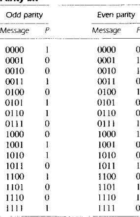
Binary information can be transmitted from one location to another by electric wires or other communication medium. Any external noise introduced into the physical commu-nication medium may change some of the bits from 0 to I or vice versa. The purpose of an error-detection code is to detect such bit-reversal errors. One of the most common ways to achieve error detection is by means of a parity bit. A parity bit is an extra bit included with a message to make the total number of l' s transmitted either odd or even. A message of four bits and a parity bit P are shown in Table 1-3. If an odd parity is adopted, the P bit is chosen such that the total number of 1 's is odd in the five bits that constitute the message and P. If an even parity is adopted, the P bit is chosen so that the total number of I's in the five bits is even. In a particular situation, one or the other parity is adopted, with even parity being more common.
The parity bit is helpful in detecting errors during the transmission of information from one location to another. This is done in the following manner. An even parity bit is generated in the sending end for each message transmission. The message, together with the parity bit, is transmitted to its destination. The parity of the received data is
TABLE 1·3
Parity bit
- - -
-Odd parity Even parity
- - -
----_._--Message P Message P - - - "
-0000 I 0000 0
0001 0 0001 I
0010 0 0010 I
0011 I 0011 0
0100 0 0100 I
0101 I 0101 0
0110 I 0110 0
0111 0 0111
1000 0 1000
1001 1001 0
1010 I IO!O 0
lOll 0 1011 I
1100 I 1100 0
1101 0 1101
1110 0 II ]() I
1111 1111 0
[image:29.545.219.362.361.583.2]-Gray Code
Section 1·7 Binary Codes 21
checked in the receiving end. If the parity of the received information is not even, it means that at least one bit has changed value during the transmission. This method de-tects one, three, or any odd combination of errors in each message that is transmitted. An even combination of errors is undetected. Additional error-detection schemes may be needed to take care of an even combination of errors.
What is done after an error is detected depends on the particular application. One possibility is to request retransmission of the message on the assumption that the error was random and will not occur again. Thus, if the receiver detects a parity error, it sends back a negative acknowledge message. If no error is detected, the receiver sends back an acknowledge message. The sending end will respond to a previous error by transmitting the message again until the correct parity is received. If, after a number of attempts, the transmission is still in error, a message can be sent to the human operator to check for malfunctions in the transmission path.
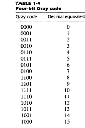
Digital systems can be designed to process data in discrete form only. Many physical systems supply continuous output data. These data must be converted into digital form before they are applied to a digital system. Continuous or analog information is con-verted into digital form by means of an analog-to-digital converter. It is sometimes convenient to use the Gray code shown in Table 1-4 to represent the digital data when it is converted from analog data. The advantage of the Gray code over binary numbers is that only one bit in the code group changes when going from one number to the next. For example, in going from 7 to 8, the Gray code changes from OJ 00 to 1100. Only the
TABLE 1·4
Four-bit Gray code
Gray code
0000 0001 0011 0010 0110 0111 0101 0100 1100 1101
1111
1110 1010 1011 1001 1000
Decimal equivalent
o
I
2 3 4
5
6 7
8
9
10
II
[image:30.544.211.356.363.582.2]22 Chapter 1 Binary Systems
first bit from the left changes from 0 to 1; the other three bits remain the same. When comparing this with binary numbers, the change from 7 to 8 will be from 0111 to 1000, which nuses all four bits to change values.
The Gray code is used in applications where the normal sequence of binary numbers may produce an error or ambiguity during the transition from one number to the next. If binary numbers are used, a change from 0111 to 1000 may produce an intermediate erroneous number 1001 if the rightmost bit takes more time to change than the other three bits. The Gray code eliminates this problem since only one bit changes in value during any transition between two numbers.
A typical application of the Gray code occurs when analog data are represented by continuous change of a shaft position. The shaft is partitioned into segments, and each segment is assigned a number. If adjacent segments are made to correspond with the Gray-code sequence, ambiguity is eliminated when detection is sensed in the line that separates any two segments.
ASCII Character Code
Many applications of digital computers require the handling of data not only of num-bers, but also of letters. For instance, an insurance company with thousands of policy holders will use a computer to process its files. To represent the names and other perti-nent information, it is necessary to formulate a binary code for the letters of the alpha-bet. In addition, the same binary code must represent numerals and special characters such as $. An alphanumeric character set is a set of elements that includes the 10 deci-mal digits, the 26 letters of the alphabet, and a number of special characters. Such a set contains between 36 and 64 elements if only capital letters are included, or between 64 and 128 elements if both uppercase and lowercase letters are included. In the first case, we need a binary code of six bits, and in the second we need a binary code of seven bits.
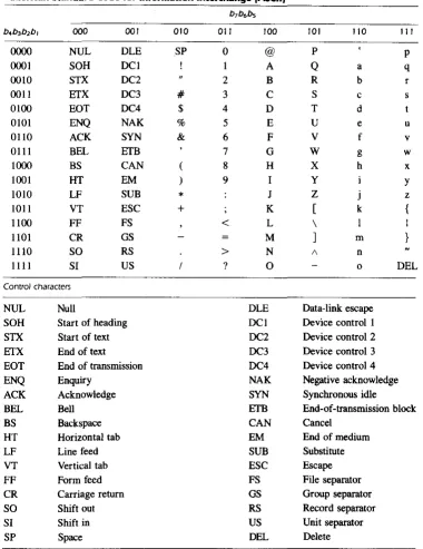
The standard binary code for the alphanumeric characters is ASCII (American Stan-dard Code for Information Interchange). It uses seven bits to code 128 characters, as shown in Table 1-5. The seven bits of the code are designated by b, through b, , with b, being the most-significant bit. The letter A, for example, is represented in ASCII as 1000001 (column 100, row 0001). The ASCII code contains 94 graphic characters that can be printed and 34 nonprinting characters used for various control functions. The graphic characters consist of the 26 uppercase letters (A through Z), the 26 lowercase letters (a through z), the 10 numerals (0 through 9), and 32 special printable characters such as %, *, and $.
Section 1·7 Binary Codes 23
TABLE 1-5
American Standard Code for Information Interchange IASCII)
b7b6bs
b4b3b2b, 000 001 010 Oil 100 101 liD III
0000 NUL DLE SP 0 @ P P
0001 SOH DCI A Q a q
0010 STX DC2 " 2 B R b r
0011 EfX DC3 # 3 C S c s
0100 EOT DC4 $ 4 D T d
0101 ENQ NAK % 5 E U e u
OlIO ACK SYN & 6 F V f v
0111 BEL EfB 7 G W g w
1000 BS CAN ( 8 H X h x
1001 HT EM ) 9 I Y Y
1010 LF SUB
•
J Z j z1011 VT ESC
+
K [ k {1100 FF FS
<
L \ I1101 CR GS M
1
m }1110 SO RS > N A n
1111 SI US ? 0 0 DEL
Control characters
NUL Null DLE Data-link escape
SOH Start of heading DCI Device control I
STX Start of text DC2 Device control 2
EfX End of text DC3 Device control 3
EOT End of transmission DC4 Device control 4
ENQ Enquiry NAK Negative acknowledge
ACK Acknowledge SYN Synchronous idle
BEL Bell EfB End-of-transmission block
BS Backspace CAN Cancel
HT Horizontal tab EM End of medium
LF Line feed SUB Substitute
VT Vertical tab ESC Escape
FF Form feed FS File separator
CR Carriage return GS Group separator
SO Shift out RS Record separator
SI Shift in US Unit separator
[image:32.544.111.491.80.572.2]24 Chapter 1 Binary Systems
separate the data into divisions such as paragraphs and pages. They include characters such as record separator (RS) and file separator (FS). The communication-control char-acters are useful during the transmission of text between remote terminals. Examples of communication-control characters are STX (start of text) and ETX (end of text), which are used to frame a text message when transmitted through telephone wires.
ASCII is a 7 -bit code, but most computers manipulate an 8-bit quantity as a single unit called a byte. Therefore, ASCII characters most often are stored one per byte. The extra bit is sometimes used for other purposes, depending on the application. For exam-ple, some printers recognize 8-bit ASCII characters with the most-significant bit set to O. Additional 128 8-bit characters with the most-significant bit set to I are used for other symbols such as the Greek alphabet or italic type tont. When used in data com-munication, the eighth bit may be employed to indicate the parity of the character.
Other Alphanumeric Codes
Another alphanumeric code used in IBM equipment is the EBCDIC (Extended Binary-Coded Decimal Interchange Code). It uses eight bits for each character. EBCDIC has the same character symbols as ASCII, but the bit assignment for characters is different. As the name implies, the binary code for the letters and numerals is an extension of the binary-coded decimal (BCD) code. This means that the last four bits of the code range from 0000 though 1001 as in BCD.
When characters are used internally in a computer for data processing (not for trans-mission purposes), it is sometimes convenient to use a 6-bit code to represent 64 char-acters. A 6-bit code can specify 64 characters consisting of the 26 capital letters, the 10 numerals, and up to 28 special characters. This set of characters is usually sufficient for data-processing purposes. Using fewer bits to code characters has the advantage of re-ducing the space needed to store large quantities of alphanumeric data.
A code developed in the early stages of teletype transmission is the 5-bit Baudot code. Although five bits can specify only 32 characters, the Baudot code represents 58 characters by using two modes of operation. In the mode called letters, the five bits en-code the 26 letters of the alphabet. In the mode called figures, the five bits encode the numerals and other characters. There are two special characters that are recognized by both modes and used to shift tram one mode to the other. The letter-shift character places the reception station in the letters mode, after which all subsequent character codes are interpreted as letters. The figure-shift character places the system in the ligures mode. The shift operation is analogous to the shifting operation on a typewriter with a shift lock key.