NOTICE
Advanced Digital does not assume any liability arising out ot the application or use ot any products, circuit or sottware described herein, neither does i t convey any license under its patent rights nor the patent rights ot others. Advanced Digital tutther reserves the right to make changes to any products
TABLE OF CONTENTS Section 1 .1 1.2 1.3 1.4 1.5 2.1 2.2 2.3 3 .1 3.2 3.2.1 3.2.2 3.2.3 3.3 3.4 3.5 4.1 4.2 4.3 4.4
SECTION 1 GENERAL INFORMATION
Introduction
System Contigurations Purpose ot Manual
How The Manual Is Organized Related Documents
SECTION 2 SUPER STAR PHYSICAL DESCRIPTION
Maintrame Front Panel Maintrame Internal Parts Maintrame Rear Panel
SECTION 3 INTERFACE CONNECTORS
Intertace Connectors Location Serial 1/0 Port Connectors Typical Three-wire Intertace Four-wire Intertace
Serial Printer Intertace Parallel 1/0 Port Connectors I/O Port Contigurations
Internal Ribbon Cable Connectors
SECTION 4 SYSTEM SPECIFICATIONS
Introduction
System Power Requirements Specitications
Changing AC Input Voltage trom
110/220 to 220/110
Section 6.1 6.2 6.2.1 6.2.2 6.2.3 6.3 6.3.1 6.3.2 6.4 6.4.1 6.4.2 6.4.3 6.4.4 6.4.5 6.4.6 6.5 6.5.1 6.5.2 6.5.3 6.5.4 6.5.5 6.5.6 6.6 6.7 6.7.1 6.7.2 6.7.3 6.7.4 6.7.5 6.7.6 6.B 6.B.1 6.B.2
TABLE OF CONTENTS (Continued)
SECTION 6 THE OPERATING SYSTEM
Introduction
Contiguring The SUPER STAR System
SUPER STAR CP/M Hardware Contiguration SUPER STAR TurboDOS Hardware Contiguration He1ptu1 Hints When Setting Up a
TurboDOS Multi-User System . Basic Operating System Structure
CP/M TurboDOS
Single User System (CP/M 2.2)
Copying Hard Disk to Diskettes
Copying Hard Disk to Cartridge
Copying Cartridge to Diskette Copying Cartridge to Fixed Disk Copying Diskettes to Fixed Disk Copying Diskettes to Cartridge Single User System (CP/M 3.0) Copying Fixed Disk to Diskette Copying Fixed Disk to Cartridge Copying Cartridge to Diskette Copying Cartridge to Fixed Disk Copying Diskettes to Fixed Disk Copying Diskettes to Cartridge Setting Real Time Clock
Multi-User System (TurboDOS) Copying Fixed Disk to Diskettes Copying Fixed Disk to Cartridge Copying Cartridge to Diskette Copying Cartridge to Fixed Disk
Copying Diskettes to Fixed Disk Copying Diskettes to Cartridge
Error Message Summary CP/M
TurboDOS
SECTION 7 LIST OF RECOMMENDED PERIPHERALS AND SOFTWARE
7.1
7.2
Recommended Peripherals Recommended Sottware
Section
8.1 8.2 8'.3
TABLE OF CONTENTS (Continued)
SECTION 8 PROBLEN ISOLATION
Introduction The First Step
Isolating A Hardware Problem
SECTION
9 BaST TO SUPER STAR COMMUNICATIONS
9.1 Introduction
SECTION 11 CP/M AND TURBODOS SOFTWARE DIRECTORIES
10.1 10.2 10.3 10.4
Introduction
CP/M 2.2 Directory
CP/M 3.0 Directory
TurboDOS Directory
Page
8-1 8-1 8-1
9.1
10-1 10-1 10-1
A A.l A.2 B C D E E.l E.2 E.3 E.4 F G
TABl.E OF CONTENTS (Continued)
APPENDICES
Care and Handling at Diskettes and cartridge Dis k e t. t f: ~;
Cartridge Disks ASCII
warranty
System Contigur~tion
Internal Ribbon and Power Cable Connections Intrortuctjon
Internal Ribbon Cables
Internal Cable COllncctor Pin Assignments Power SupJ?ly
SUPER STAR Parts List System Schematics
LIST OF ILLUSTRATIONS
f 19nre
2-1 2-2 2-3 A-I 1\-2 E-1 E-2 Table 3-1 3-2 4-1 4-2 4-3 4-4 4-5 4-6
SUPER S'l'l\R Front Panel
SUPER STAR Internal Section
SUPSR STAR Rear Panel Floppy Diskettes
Cartridqe Disks
Internal RilJbon Cables
SUPER STAR Power Supply Schematic Diagram
LIST OF TABLES
Serial I/O Port Pin Assign~ents
Parallel 1/0 Port Pin Asslgnm8nts SUPER QUAD CPU Module
SlIPER SIX CPU Module
Hard Disk Drive and Controller Subsy~tem
Flnupy Disk Drive SUP EnS 1.1\
'n.;
r'lO c1 u 1 eSUP E R SLAV E Ov era 11 S pe c i t i cat i CH J S
Table
6-1
6-2 E-l E-2
E-3
E-4
TABLE OF CONTENTS (Continued)
LIST OF TABLES (Continued)
SUPER SLAVE Switch Sl Address Setting USERID. SYS File Layout
5-100 Bus Motherboard Pin Assignments CPU Board Ribbon Cable Connector Pin
Assignments
DMA Board Ribbon Cable Connector Pin Assignments
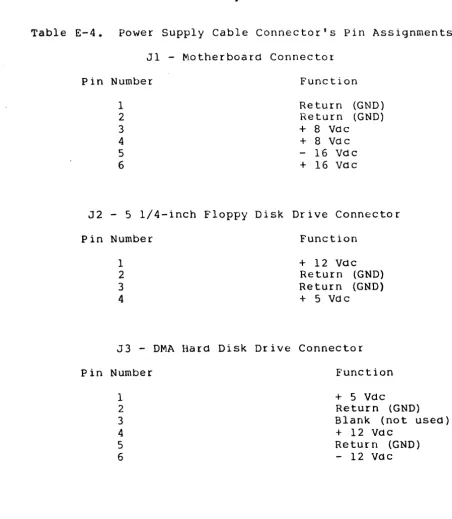
Power Supply Connector's Pin Assignments
Page
6-2
6-2
E-2
E-3
SECTION 1
GENERAL INFORMATION
1.1 Introduction
The Advanced Digital SUPER STAR is the most advanced 8-bit or 16-bit, 5-100 bus-based single user/stand-alone and IDulti-user/multi-processing computer system in today's marketplace tor business, protessional and educational applications. When contigured as a single-user, stand-alone system, the CP/M Operating S'ystem allows access to a vast library ot ap~lication sottware packaqcs. Add the TurboDOS Operating System and trom one to tour StTpt;:R Sl.AnE modules and the SUPER STAR becomes a multi-task networking system
tor up to twelve users. With either contiguration, SUPER STAR otters the tollowing teatures:
- 10 Mbyte 5 l/4h ~inchestcr Hard Disk Drive 5Mbyte tixed and 5Mbyte removable cartridge) - Separate Hard Disk Controller module tor high speed data transter
- 5 1/4", Halt-high, 48 TPI Floppy Disk Drive Six-slot, 5-100 Bus compatible motherboard
- 4 MHz, Z80A CPU, Floppy Disk Controller,
64 Kbyte RAM, 2K (or optional 4K ) monitor EPROM, Optional Z80B PIO and SIO SUPER SIX with optional 1?8 Kbyte RAM
- Contigurable tor up to tive users using SUPER SLAVE modules with TurboDOS or as a single-user st0nd-alone systpm with CP/M 2.2/3.0 or TurboDOS
- Slim-line, selt-contained cabinet
1.2 System Contigurations
Single User Systems
-SUPER QUAD or SUPER SIX (optional) -4R TPI Floppy Dibk Drive
-10 Mb Hard Disk w/Controller 5Mb removablp-/5 Mb Fixed -CP/M 2.2 or CP/M 3.0
-TurboDOS
General Intormation
Multi-user System
-SUPER QUAD or SUPER SIX (optional) -One SUPER SLAVE (4 MHz or 6 MHz)
-48 TPI Floppy Disk Drive
-10 Mb Hard Disk w/Controller
5Mb removable/5Mb tixed -TurboDOS
1.3 Purpose ot Manual
This manual has been designed to supply the intorrnation needed by
the stand-alone or multi-tasking user to install, contigure and
operate the SUPER STAR. Intormation is also provided tor
identitying and then isolating the problem, it it should occur,
to determine it the problem can be solved simply by the user or
it it must be retered to a qualitied service organization. The
manual has been written at a system level (i.e., the complete
SUPER STAR) and does not attempt to discuss specitic design
characteristics ot individual modules or the operating system
sottware within the system. That intor~ation is contained in
individual manuals also supplied with the SUPER STAR system.
1.4 Bow The Manual Is Organized
This manual is organized into seven sections and tive Appendices.
The subjects covered by each section and appendix are listed
below:
Section 1,
Section 2,
Section 3,
Section 4,
Section 5,
General Intormation - Intormation to the SUPER
STAR and this manual.
SUPER STAR Physical Description - Explanation
ot the tront panel, rear panel and internal layout.
Intertace Connectors - Description ot 1/0 ports
and associated connectors as well as
contiguration considerations.
System Specitications - SUPER STAR
specitications at a system and module level.
Instalation and Initialization - Intormation
on setting up and initializing the SUPER
General Intormation
Section 9, Host to SUPER STAR Communications - How to set
up the SUPER STAR and a host system to transter data tiles between systems.
Section 10, CP/M and TurboDOS Sottware Directories
-Listings ot each ot ditterent operating system directories.
Append ix A,
Appendix B,
Appendix C,
Appendix 0,
Appendix
E,
Care and Handling ot Diskettes and Cartridge
Disks - Cautions on how to handle, store and
prevent problems with disks and diskettes.
ASCII Character Set - Tabular listing ot the
ASCII code and the corresponding alphanumeric characters.
Warranty - Advanced Digital's warrenty program.
System Contiguration - Your checklist tor
identiting your SUPER STAR contiguratio~ and
serial numbers.
Internal Ribbon and Power Cable Connections
-How internal ribbon connectors intertace on a
pin-to-pin basis with modules and power supply
layout. .
Appendix F, Parts List - General l i s t ot all parts which
makeup the SUPER STAR system.
1.5 Related Documents
The tollowing is a l i s t ot related documents which will help in
the use and understanding ot the SUPER STAR system:
SUPER QUAD S-100 Single Board Computer Technical Manual SUPER SLAVE Technical Manual
HDC-1001 Hard Disk Controller Technical Manual TurboDOS User's Guide
DMA Hard Disk Manual
CP/M 2.2 OR 3.0 User's Manual
SECTION 2
SUPER STAR PHYSICAL DESCRIPTION
2.1 Maintrame Front Panel
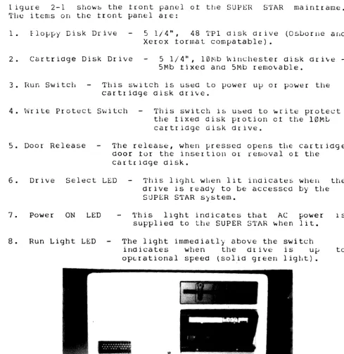
ligure 2-1 show~ the tront panel ot the SUPEH STAR maintrame.
frile items on the tront panel are:
1. flo~py Disk Drive 5 1/4", 48 'l'Pl disk Or ive (Osborne arld Xerox tormat compatable).
2. Cartridge Disk Drive 5 1 / 4
1\,
1 0 1Vi bw
i r 1 C 11 est e r dis k d r i \t e-5Mb tixed and -5Mb removable.
3. H.un Switcb Tbis switch is Lised to power ulJ or power the cartridge disk drive.
4. Wrlte Protect Switch This switch is used to ~rite protect the tixed disk protion ct the 10Mt cartridge disk drive.
5. Door Release The release, when pressed opens tl1e cartridge door tor the insertion Ot removal ot the
cartridge disk.
6. Drive Select LED This 1iqhL wilen l i t indicates WIlE=ll the drive is ready to be accessed by tbe SUPER STAR system.
7. Power ON LED
8. Run Light LED
This light indicates that AC power 1S supplied to tbe SUPER STAR when lit.
The light immeaiatly above the switch
indicates when the drivE: is up to 0pE.:rational speed (solid green light).
~li.'
[image:11.623.66.555.160.663.2]I
Supersta'..£J
2
SUPER STAR Physical Description
2.2 Maintrame Internal Parts
Figure 2-2 shows the major internal parts ot the SUPER STAR system maintrame.
1. Internal Card Cage - The SUPER STAR system can support up to six ditterent modules. One SUPER QUAD or SUPER SIX CPU module, one hard disk controller, and up to tour SUPER SLAVE modules tor mUlti-user applications. 2. Rear Panel Connector - Ribbon cables which connect the
internal mOdules ot the SUPER STAR system to the rear panel and external 1/0 devices. The maximum number ot 1/0 connectors is seven. NOTE
Care should be taken to assure the cable connector is properly connected. The red edge ot the ribbon cable always denotes Pin 1. You can assure proper connection by making sure that the ribbon cable is plugged into the connector with the pin 1 edge aligned with the" n on the connector receptacle. 3. Disk Drives - 5 1/4" and 10Mb disk drives.
4. Cooling Fan - The cooling tan circulates air to maintrame an operating temperature which averages below 115 F inside the SUPER STAR system maintrame.
5 • Power Supply - The power supply provides DC power to internal modules such as, the CPU, controller and any Slave modules present. It also provides power to disk drives.
SUPER STAR Pbysical Description
2.3 Maintrame Rear Panel
Figure 2-3 shows the rear panel ot the SUPER STAR maintrame. The items on the rear panel are:
1. Power On Switch Turns on the At power to the SUPER STAR system.
2. Reset Button When this button is pressed, the system is reset by the operating system and the operating system sottware is reloaded into system memory.
3. Power Cord Plug Supplies AC power connection tor the SUPER STAR.
4 • Fuse - The tuse provides line protection tor the SUPER system. See Section 4 tor the proper type ot to use and how to replace or change the requirement. The tuse section contains a printed-circuit board to support both 110V and AC power.
STAR tuse power small
220V
5. 1/0 Connectors These seven ports can support master console, tour additional slave consoles, a printerport and communications port. 6. Cooling Fan The cooling tan circulates air to maintain an
2
6
o(
)0
o(
)0
0\
)0
o(
/0
0\
-,0
I I O(--~O'i
o
U~, ]:~
Q)(:::::::~:':P
II
t
(Wi:>i.~J
Ii
;~
'"""..A.
r"-- ---
----~
3 4
SECTION 3
INTERFACE CONECTORS 3.1 1ntertace Connectors Location
The SUPER STAR system has seven I/O intertace connectors located on the rear panel as shown in Figure 2-3. Five connectors are 25-pin type OB-25 connectors, which require a type DB-25 mating connector tor intertace to serial peripheral devices. These tive connectors are tor RS-232C compatible serial 1/0 intertace. Two connectors are parallel intertace ports (Centronics compatible) and are 25-pin type DB-25 connectors that require type DB-25 mating connectors.
NOTE
Not a l l o t these seven 1/0 intertace are necessarily internally wirea to circuit boards in the SUPER STAR, depending upon the contiguration you have ordered.
See paragraph 3.4 entitled, 1/0 Connector Contigurations.
3.2 Serial I/O Port Connectors
One ot the tive serial 1/0 port connectors is intended tor intertacing a monitor/keyboard/terminal console. This connector is intendea as Jl. The other tour serial 1/0 port connectots (J2 through J5) are intended tor intertacing a serial printer and/or any other serial communications peripheral devices.
All tive serial 1/0 port connectors have the assignmentssince they are all RS-232C compatibe. identities the pin assignments tor these connectors.
same pin Table 3-1
Table 3-1.
Pin No. 1
2 3 4
Serial 1/0 Port Pin Assignm~nts
Signal Assignments System Ground
Interlace Connectors
3.2.1 Typical Three-Wire lntertace
The simplest 1/0 port intertace requires only three ot the serial 1/0 connector be wired. These three wires are: Pin 2-TxD, Pin 3-RxD ana Pin 7-Signal Ground. This three-wire contiguration will satisty many serial devices and most terminals.
3.2.2 Four-Wire 1ntertace
Some serial devices require a "handshake" signal tor normal protocol. In these cases the tour-wire intertace contiguration will normally work. This contiguration is the safiLe as the three-wire contiguration (pins 2,3 and 7 connected with the additional tourth wire being pin 20 - DTR).
3.2.3 Serial Printer lntertace
Most serial printers require a "Busy" signal to maintain data tlow. With such printers, the tour-wire contiguration will normally work where pin 20 - DTR, is used as the "Busy" signal.
3.3 Parallel I/O Port Connectors
The two parallel I/O port connectors (J6 and J7) have the pin assignments and are Centronic printer compatible. The assignments tor these two connectors are shown in Table 3-2.
same pin
One ot the parallel I/O port 25-pin connectors is driven by the SUPER QUAD PlO channel A, the other is driven by the PlO channel B. Table 3-2 does not distinguish between A or B since both are the same.
Interface Connectors
Table 3-2. Parallel 1/0 Port Pin Assignments
Pin Number PIO Signal Name Signal Function
1 ASTRB/BSTRB Strobe
2 PA2/PB2 Data Line 2
3 PAO/PBO Data Line (3
4 Not Used
5 PAI/PBI Data Line 1
6-8 Not Used
9 PA3/PB3 Data Line 3
10 Not Used
11 PA4/PB4 Data Line 4
12 Not Used
13 PA5/PB5 Data Line 5
14 Not Used
15 PA6/PS6 Data Line 6
16 Not Used
17 PA7/PB7 Data Line 7
18 Not Used
19 ACKNLG
20 Not Used
21 BUSY
22-24 Not Used
Intertace Connectors
3.4
1/0 Port ContigurationsThe number ot the I/O port connectors that are actually connected
(through ribbon cables) to printed circuit boards inside the
SUPER QUAD is dependent upon the ~articular contiguration you
have selected tor your SUPER STAR system.
A CP/M-based single-user SUPER STAR system has tour ot the seven
1/0 port connectors available to the user (see options). These
consist ot one parallel port connector and two serial ports (Jl
and J2). This contiguration will support a terminal/keyboard
(one ot the serial ports), one serial peripheral (perhaps a
printer) and a parallel peripheral (printer, plotter,' etc.).
A TurboDOS-baseo multi-user SUPER STAR system can have trom tive
to the total seven 1/0 connectors available to the user depending
upon the number ot SUPER SLAVE modules installed in the SUPER
STAR. A tully contigured TurboDOS-based multi-user SUPER STAR can
support a master terminal/keyboard (one ot the tive serial 1/0
ports), tour remote user stations (the other serial 1/0 ports)
and two parallel 1/0 peripheral devices.
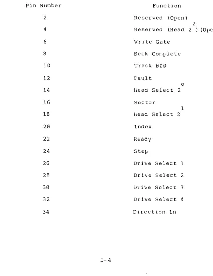
3.5 Internal Ribbon Cable Connectors
In case trouble is encountered with rear chassis 1/0 connectors
that requires an understanding ot the actual pin-to-pin
allocations ot ribbon cables trom the SUPER QUAD or SUPER SLAVE
modules to the 1/0 connectors, reter to Appendix E. Under normal
use, and during system contiguration this intormation is not
required and theretore is not presented in this section.
SECTION 4
SYSTEM SPECIFICATIONS
4.1 Introduction
This section presents speciticationjntormation on the overall
SUPER STAR system as well as individual subsystems (such as the
tloppy disk drive and the hard disk drive).
4.2 System Power Requirements
The SUPER STAR operates on 110 or 220 volts AC, 50-60 Hz power
and is contigured at the tactory tor the power requirements ot
the country ot destination.
When contigured tor 110 VAC, the SUPER STAR is rated at 5 amperes
max. (625 watts). When contigured tor 220 VAC, the SUPER STAR is
rated at 2.5 amperes max. (625 watts).
NOTE
I t the SUPER STAR is not contigured tor the AC power used at your tacility, reter to section
4.4, Changing AC Voltage, tor the proper procedure.
4.3 Specitication Tables
The tollowing tables present specitications (and operating
parameters) tor SUbsystems and circuit boards associated with the
SUPER STAR system. The subsystems covered by these tables are as
tollows:
Table 4-1 SUPER QUAD CPU Module
Table 4-2 SUPER SIX CPU Module (optional)
Table 4-3 Hard Disk Drive and Controller Subsystem
Table 4-4 Floppy Disk Drive
Table 4-5 SUPER SLAVE fvlodule
Table 4-6 SUPER STAR Overall Specitications
System Specitications
Table 4-1. SUPER QUAD CPU Module Specitications.
Parameter Specitication
Bus Structure
CPU
SIO, PIO
RAt-1
ROM
Floppy Disk Controller
Counter/Timer Controller
Motherboard Slot
5-100 Compatable, IEEE 696
zilog Z-80A, 4 MHz
zilog Z-80A, 4 MHz
(two Rs-232C serial ports and two parallel ports)
64K bytes, bank selectable (16K bytes)
2K (4K optional) 2716 EPROM
Monitor ~ontains BOOT
routine, momory FILL,
memory DUMP, PRINT, MOVE,
1/0 Read/Write, and
Executive Address. Occupies
memory address FOOO through
F800 (2K) or FOOO through
FFFF (4K). Also contains
SID and FDC initialization code.
WD1793 FDC. Supports
5 1/4" or 8" Floppy disk drives.
Zilog Z80A CTC tor 4 MHz
Real Time interrupt
clock.
System Specitications
Table 4-2. SUPER SIX CPU Module Specitications.
Parameter Specitication
Bus Structure 5-100 Compatable, IEEE 696
CPU Zilog Z-80B, 6 MHz
510, PIO Zilog Z-80B, 6 MHz
(two Rs-232C serial ports and two parallel ports)
RAM 64K or 128K bytes (optional),
bank selectable (16K bytes)
ROM .. 2K (4K optional) 2716 EPROM
Monitor· contains BOOT routine, memory FILL, memory DUMP, PRINT, MOVE, 1/0 Read/Write, and
Executive Address. Occupies memory address FOOO through FFFF (4K). Also contains 510 and FDC initialization code. Floppy Disk Controller
Counter/Timer Controller
Motherboard Slot
4-3
WD2793 FDC. Supports 5 1/4" or 8" Floppy disk drives simultaneously. Zilog Z80B CTC tor 6 MHz Real Time interrupt clock.
System Specitications
Table 4-3. Hard Disk Drive and Controller Subsystem Specitications
Parameter
Drive Type
Number ot Disk Drives
Number ot Heads/Surtaces
Storage Capacity
Subsystem Fixed Disk Removable Disk Sectors Per Track Bytes Per Sector Bytes Per Track
Data Transter Rate
Data EnCOding Method
Step Rates
Average Latency Time
Controller
Specitication
DMA System's Micro-Magnum 5/5 or any ST506 compatible
intertace.
Two 5 1/4" standard Winchester
type drives one tixed,
one removable.
4 (2 tixed, 2 removable)
Formatted
10.8 Mbytes 5.4 Mbytes 5.4 Mbytes 32+1 spare 256
8,192
5.0 Mbytes/sec
MFM
Untormatted
12.8 Mbytes 5.4 Mbytes 5.4 Mbytes 33
304 10,032
35 usecs (detault)
Selectable tor 0.5 to 7.5 usecs in 0.5 usec increments.
8.7 usec
System Specitications
Table 4-4. Floppy Disk Drive Specitications •
. Parameter Specitication
Disk Contiguration
Diskette Format
Tracks per Inch
4-5
Double-density,double-sided 5 1/4" tloppy diskette. Osborne cornpatable (single density)
Xerox cornpatable KayPro compatable
System Specitlcations
Table 45. SUPER SLAVE Module Specitications.
Parameter Specitications
Internal CPU Control
Serial I/O Ports
Parallel I/O Ports
Interrupt Control
Bus Intertace
Sottware Controll
RAM
ROM
Power Requirements
Zilog Z80A, 4 MHz CPU
6 MHz (optional) Four Serial 1/0 ports
(RS232C or RS422 compatible)
Two parallel 1/0 ports 25 pins each.
AMD9519 controller with vectorea interrupt contiguration possible.
S100, IEEE696
Standard bus compatible.
TurboDOS multi-user operating system.
64K or 128K bytes ot banked switched memory.
2K or 4K bytes ot EPROM.
+8 volt DC @ 1.5 Amps
System Specltlcations
Table 4-6. SUPER STAR Overall Specitications.
Parameter Specitications
CPU Moaule SUPER QUAD or optional
SUPER SIX module
Disk Controller HDC10015 Hard Disk Drive Controller module
1/0 Controller Modules
Number ot Motherboard Card Slots
Hard Disk Drive
Floppy Disk Drive
Operating System
Power Requirements
Dimensions
4-7
Up to tour SUPER SLAVE modules tor peripheral controller.
6
DMA MicroMagnum 5/5
5 1/4" 10 Mbyte (5 Mbyte tixed, 5 Mbyte removable) Disk Drive.
48 TPI Floppy Disk Drive 5 1/4", low protile, 308 bytes, double density,double sided diskette.
Single User MultiUser TurboDOS 1.30
CP/M 2.2
TurboDOS 1.30 CP/M 3.0
110 VAC, 5 A, 625 watts 220 VAC, 2.5 A, 625 watts
Height Width Length
6.5 inches (16.51 cm) 13.5 inches (34.29 cm)
System Specitications
4.4 Changing AC Input Voltage trom 110/220 to 220/110 1. Remove
connected. the lett. plug.
!
the power cord trom the rear ot the system it it is Slide the plastic cover which is covering the tuse to The plastic cover should now be covering the power
2. Gently pull on the black tab to remove the tuse. The tab releases the tuse trom its holder and will pivot tram the lett-hand end ot the tuse.
3. Remove the tuse and set it aside.
4.
Using a pair ot small pliers, gently pull ~he small circuit card straight out at the slot holding it. Be caretul not to bend the board as this may cause the board to maltunction, causing electrical damage to the SUPER STAR system.5. Orient the board as shown below to set the proper AC power specitication. You will notice that the number which- is rightside up, is the power speciticstion which the circuit board will operate under.
110 Setting 220 Setting
CAUTION
Do not use the incorrect setting on the circuit board as this may cause severe electrical damage to your system.
6. Gently reinsert the circuit board into the slot, again being caretul not to bend the board.
7. Press the tuse back in place. PreSSing the tuse into place causes the black tab to move back into its original position and
locks the tuse in place.
II
.:
3 ":. n .:i •. ;1;~)<3 H~~
l~ H ['i!-l r '_J :. E.
. "'11'
. .. .. '" ... .. ...
.. .. .. .. .. .. .. .. .. .. .. .. .. .. .. .. .. .. .. .. .. .. .. .. .. .. .. .. .. .. .. .. .. . ... ...... .. ... " " " " .. ..
.. . . . ..
I
I
.. .. .. .. .. .. ... .. .. .. .. .. .. .. .. .. .. .. .. .. .. .. ... .... .. .. .. .. .. .. .. .. .. .. .. .. .. .. ..
... .. .. .. .. .. .. .. .. .. .. .. ..
.. .. .. .. .. .. .. .. .. .. .. .. .. .. .. ..
.. .. . .. .. .. .. .. . .. .. .. .. .. .. .. .. .. .. .. .. .. .. .. .. .. .. .. ..
.. .. .. .. .. .. .. .. .. .. .. .. .. .. .. .. .. .. .. .. .. .. .. .. .. .. .. .. .. .. .. .. .. ... .. ... ..
SECTION 5
INSTALLATION AND INITIALIZATION
This section explains the procedures necessary to setup and
initialize the SUPER STAR system. There are operating system
backup procedures given tor both CP/M and TurboDOS operating
systems.
5.1 Installation Procedure
1. Betore removing the SUPER STAR maintrame trom its shipping
container, inspect the outside ot the container. It any damage
is tound, notity the shipping company and Advanced Digital
immediately.
2. Caretully remove the SUPER STAR trom the shipping container.
Inspect the exterior ot the maintrame tor any damage. It any
damage is tound, notity the shipping company and Advanced Digital immediately.
3. place the SUPER STAR maintrame on a level counter or desk
top.
4. Open the SUPER STAR maintrame by removing the cover and check
the seating ot the boards and cable connections.
5. Connect the master console to the proper rear panel 1/0
connector marked "1" at the rear ot the SUPER STAR system.
CAUTION
Check the tuse package at the rear ot the SUPER STAR system. You should be able to read the lettering on
the small circuit board which is inserted under the
tuse. It the number which you can read rightside up
is not the proper voltage STOP STOP STOP!!! Turn to
Installation and Initialization
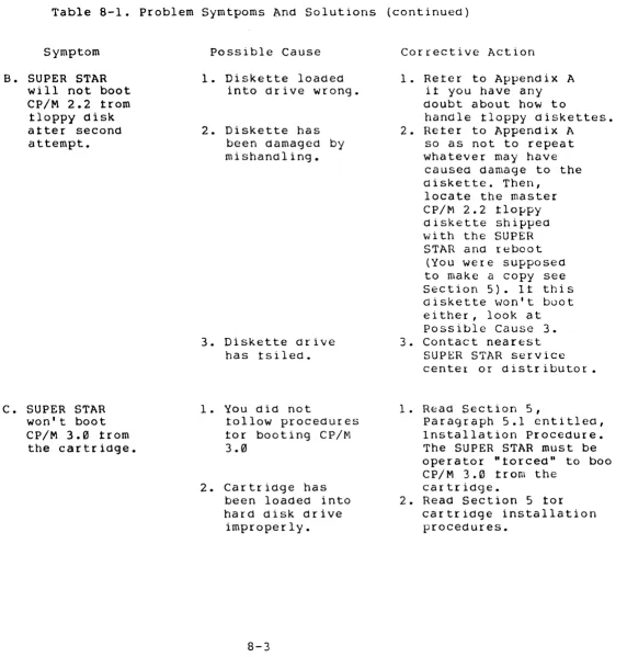
5.1 Installation Procedure (continued)
6. Turn the power switch to the OFF position on SUPER STAR it it is not already in that position. power cord to the rear ot the SUPER STAR system. power cord to the rear ot the console and plug it source, but do not power up the system console.
NOTE
the console and Connect the AC Connect the AC into a power
The power switch on the SUPER STAR system is in the OFF position it the power switch light is not l i t and ON when the the light in the power switch is l i t .
7. Press the power switch ot the SUPER STAR into - the ON position. The LED on the switch should light. The LED on the
tloppy disk drive should also be l i t . This indicates that the SUPER STAR is trying to access data trom the tloppy disk drive.
8. Open the cartridge drive door by pressing the disk release button (see Figure 2-1) and gently lowering the cartridge drive door.
9. Insert a cartridge, either blank (it using CP/M) or an
operating system (it using TurboDOS or CP/M 3.0) into the drive. Make sure that the red write protect tab is in the lower right-hand corner tacing you. The bottom ot the cartridge is the side which ahs the circular metal plate, this side must be tacing down when the cartridge is inserted into the drive. See Appendix A it you are not tamiliar with diskettes and cartridge disks. Gently slide the cartridge into the drive, pressing on the lett tront side ot the cartridge disk, until i t is properly seated.
10: Close the drive door. The cartridge should drop into position as the drive door is closed.
11. Set the Write Protect Switch to the ON position. The switch is in the "ON" position when the right-hand side ot the switch is t1ush with the tront ot the disk drive. This protects the data on the cartridge trom being damaged or being written on.
12. Press the RUN button to the ON position. The switch is in the "ON" position when the right-hand side ot the switch is tlush with the tront ot the drive. The green run light should begin to blink as the drive comes up to operating speed. When the drive is up to operating speed, the green light stops blinking and remains l i t and the red light or "ready" light comes on to indicate that the drive is ready.
Installation and Initialization
5.1 Installation Procedure (continued)
13. It you are using thr CP/M 2.2 operating system with the SUPER STAR, you could at this time insert a system diskette into the t10ppy disk drive and load the system sottware into memory. However, it you do not tollow the rest ot the procedure listed here you will not know it the hard disk drive is operational. 14. Turn on the power to the system console it you have not already done so.
15. Press the reset button on the back ot the SUPER STAR system (see Figure 2-3). The system then access the disk system in the tollowing manner:
1. Checks the tloppy drive tor a disk containing a system boot. This would be the drive which would have the CP/M operating system it you are using that operating system.
2. Checks the tixed hard disk tor a system boot. This may be where you would normally like to store your operating system whether it be CP/M 2.2, CP/M 3.0 or TurboDOS.
3. The system then retires in the sequence lidted above, tloppy, tixed disk, and back to the tloppy.
I t you wish to boot trom the cartridge you must use the tollowing procedure:
IMPORTANT - This procedured must be tollowed when booting the TurboDOS or CP/M 3.0 system contained on a cartridge tor the tirst time, i t is suggested that you copy the operating system to the tixed disk to save time under normal operation.
1. Hold the SPACE bar down and press the RESET button.
2. The system boots and calls a system monitor routine tollowed with a prompt
>.
Installation and Initialization
5.1 Installation Procedure (continued)
CP/M 2.2 Signon Message:
>ADVANCED DIGITAL CORPORATION Monitor Version n.n
April - 1983
Press "8" tor help
Attempting to boot •••••
Press any key to abnort boot
Super BIOS vn.nn Typeahead installed
60K CP/M 2.2 Installed
Detault console is serial port 1
CP/M 3.0 Signon M~ssage:
>ADVANCED DIGITAL CORPORATION
/ f't10nitor Version n.n
April - 1983
Press "H" tor help
Attempting to boot ••••• Press any key to abort boot
C P / tv! V 3 ." Lo ad e r
Copyr ight (C) 1982, Dic Res
BIOS3 SRP E500 1100
BIOS3 SPR C600 IF00
Detault printer is parallel driver 49K TPA
A> Super BIOS v.3.0
CP/M 3.0 Installed
Detault console is serial device 0 Detault printer is palallel device
A>
TurboDOS Single-User Terminal Signon Message:
>ADVANCED DIGITAL CORPORATION Monitoer Version 3.6
April - 1983
Press "8" tor help
Attempting to boot ••••• Press any key to abort boot
Copyright 1983, Sottware 2000, Inc. -(21/serial no.) A:OSMASTER,SYS loading trom EFF4 to FFFF, size 400C
TurboDOS 1.30, Copyright 1983, Sottware 2000, Inc. (serial no.) Super Six [or Quad] up.
OA}
NOTE
I t the system is being booted trom the cartridge the
prompt is OB}. The message "Super Six up" or "Super
Quad up" indicates the type at CPU module you are
using.
Installation and Initialization
5.1 Installation Procedures (continued) TurboDOS Multi-User Master Terminal Message:
>ADVANCED DIGITAL CORPORATION Monitor Version 3.6
April - 1983
Press "8" tor help
Attempting to boot ••••• Press any key to abort boot
Copyright 1983, Sottware 2000, Inc. (2l/serial no.) A:OSMASTER.SYS loading trom BFF4 to FFFF, size 400C
TurboDOS 1.30, Copyright 1983, Sottware 2000, Inc. (21/serial no.) Super Six [ or Quad] up.
OAl
TurboDOS Multi-User Slave Terminal Signon Message: >ADVANCED DIGITAL CORPORATION
Monitor Version n.n April - 1983
Press "B" tor help
~ttempting to boot ••••• Press any key to abort boot
Copyright 1983, Sottware 2000, Inc. (21/serial no.) Advanced Digital Copr. Super Slave Bank up.
OAl
NOTE
Installation and Initialization
5.2 Initial System Power-Up
When you tirst receive the Super Star system, a copy ot the
system sottwareshould be made by placing a blank cartridge into
the 10 MMb drive (hard disk) or a blank diskette into the tloppy
disk drive. The actual backup procedure tor both the TurboDOS
and CP/M operating systems are discussed in Sections 5.3 and 5.4,
respectively.
The Super Star system is designed to tirst, access the tloppy disk
drive to locate an operating system to be loaded into system
memory. It a disk or operating system is not tound in the tloppy
drive, the system then accesses the tixed portion ot the 10 Mb
hard disk drive.
When the Super Star is shipped to you, a copy ot the operating
system is provided on the cartridge disk tor TurboDOS or
cartridge tor CP/M 3.0 users, or tloppy disk tor CP/M 2.2 users.
The startup procedure discussed in Section 5.1 is the general
startup procedure tor either operating system (TurboDOS or
CP/M).
I t is suggested by Avanced Digital that you use the tixed
portion ot the hard disk as your normal operating system disk.
The cartridge disk and tloppy diskettes can be used tor storage
ot development sottware, applications and operating system backup sottware.
The cartridge disk is always used in the upper halt ot the hard
disk drive and must be inserted with the red write protect tab
in the lower right-hand corner. The side ot the cartridge with
the metal disc is termed the bottom side ot the cartridge.
Appendix A provides turther intormation on the proper use and
care ot cartridge disks.
NOTE
The tollowing paragraph applies to SUPER STAR systems which are developed with CP/M 2.2 operating system or
it you intend to use tloppy distettes with your system.
The tloppy diskettes are always used in the upper drive ot the
SUPER STAR and must be inserted with the level up. The lable
side ot the diskette is termed, the top side ot the diskette.
'Read Appendix A tor the prope~ care and handling ot tloppy
diskettes. All diskettes used in the SUPER STAR system must be
certitied tor use with double density, double-sided 48 TPI,
5 1/4" drives.
Installation and Initialization
5.3 Copying The System Disk (TurboDOS)
This section describes the protcedure tor copying the operating
system trom the cartridge disk to the tixed portion ot the hard
drive using the TurboDOS system. This procedure can also be
tollowed it the operating system on your tixed disk is damaged
and must be reloaded trom a backup cartridge or tloppy. It you
have a "SUPER STAR" system with the CP/M operating system, skip
to Section 5.4 tor the proper copy procedure.
To copy the system disk, proceed as tollows:
1. Power the system.
2. Power up the hard drive by pressing the run button on the
hard drive. When the drive is up to operating speed, reboot the
system by pressing the reset button on the back panel ot the
SUPER STAR system. Press the Run button and the R/W button on
the hard disk drive.
3. Insert a cartridge disk containing the operating system into
the 10 Mb drive it you have not already done so. This must be
done in order tor the system to boot.
4. Hold the SPACE bar down and press the RESET button.
5. The system boots and calls a system routine tollow with a
prompt -
>.
6. Typy H. When the menu is displayed, press C tor cartridge
boot tollowed by a RETURN.
7. The system reads the cartridge and loads the operating system
trom the ca~tridge disk.
8. The logon message is displayed and the TurboDOS command
prompt is displayed: OBI
9. Type, BUFFERS N2. This command initializes your terminal as
the master terminal or console.
OBI BUFFER2 N2[RETURN]
OBI BANK O[RETURN] (only it you are running with a SUPER
multi-Installation and Initialization
5.3 Copying The System Disk (TurboDOS) (continued)
10. Enter the command, FORHDC A. This command displays a menu ot ditterent types ot drives to tormat. This command tormats the tixed portion ot the hard disk. TurboDOS assigns the csrtridge portion ot the hard disk as drive B, the tixed portion drive A and the tloppy drive as drive C. NOTE: When running TurboDOS with slaves this operation must be done trom the master terminal. The tollowing set ot prompts shows the system displays:
OB}FORHDC A: [RETURN)
***
Hard Disko
=ST503selection choices
***
1 =ST506 ;Seagate Technology 2 =TM6015 3 =TM602S ;Tandon Magnetics 4 =TM603S 5 =TM603SE
6 =TM501 7 =TM502 8 =TM503
9 =SA602 10 =SA604 ;Shugart Associates 11 =SA606
12 =SA1002 13 =SA1004
14 =Q2010 15 =Q2020 iQuatum 16 =Q2030 17 =Q2040
18 =M4010 19 =M4020 ;MiniScribe
20 =DMA5/5 ;DMA System
?(tor DMA drive, you would enter 20 here) INSERT DISK TO BE FORMATTED IN DRIVE A ENTER <CR) TO BEGIN FORMATTING
·
.
. . .
.
. .
.
.
.
.
.
.
. .
. .
.
.
. . .
· .
.
. . .
.
.
.
. . .
.
. . .
. .
.
· . . . .
.
. .
.
. . .
. . . .
.
.
.
.
. .
.
Start verity
·
.
. . .
.
. . .
.
. .
.
. . .
.
·
.
.
.
.
.
.
. .
.
.
.
. .
.
. . .
. .
.
. .
OB}
11. Enter the command, ERASEDIR A:. This command clears or initializes a directory that may have been previously written on the disk. Press RETURN:
OB}ERASEDIR A: (RETURN)
12. The system displays a series ot questions, answers in the tollowing manner:
Hashea directory desired (YIN)? Y OK to erase directory on drive A? Y Erasing directory
Installation and Initialization
r
5.3 Copying The System Disk (TurboDOS) (continued)
13. The system then erases the directory and then displays: Directory erased, hashed
OB}
14. Enter the command, BACKUP B: A:. This command copies a l l o t the data currently stored on the cartridge disk (B) to the tixed disk (A):
OB}COPY B: A: [RETURN]
15. The system then displays the tollowing and waits tor you to press RETURN:
Insert source d~sk io dr~ve A. Insert dest1nat1on d1Sk 1n dr1ve B Enter (cr> to begin copying:
16. Enter TKOBOOT TRKOMA.LDR A: to copy the track zero loader onto the tixed disk.
OB}TKOBOOT TRKODMA.LDR A: [RETURN]
Installation and Initialization
5.4 Copying The System Disk (CP/M 3.0)
This section describes the procedure tor copying the operating
system trom the cartridge disk to the tixed portion ot the hard
drive using the CP/M 3.0 systems. This procedure can also be
tollowed it the operating system on your tixed disk is damaged
and must be relocated tram a backup cartridge or tloppy. It you
have a SUPER STAR system with the CP/M 2.2 operating system, skip to Section 5.5 tor additional intormation.
To copy the system disk, proceed as tallows:
1. Insert a cartridge disk containing the operating system into
the 10 Mb drive it you have rot already done so.
2. Power
hard drive. system.
up the hard drive by pressing the run button on the
When the drive is up to operating speed, reboot the
3. Hold the SPACE bar down and press the RESET button.
4. The system boots and calls a system monitor routine tollow
with a prompt -
>.
5. Type HELP. when the menu is displayed, press C tor cartridge
boot tollowed by a RETURN.
6. The system reads the cartridge and loads the operating system
trom the cartridge disk.
7. The logon message is displayed and the CP/M command prompt is
displayed:
A>
Installation and Initialization
- 5.4 Copying The System Disk (CP/M 3.0) (continued)
8. Enter the command, FMTHD. This command tormats the tixed portion ot the hard disk. CP/M assigns the cartridge portion ot the hard disk as drive A, the tixed portion drive B and the t10ppy drive as drive C. The tollowing prompts are displayed by the system:
A)FMTHD [RETURN]
***
***
Hard Disko
=ST503 2 =TM6015selection choices 1 =ST506
3 =TM602S
iSeagate Technology iTanaon Magnetics
4 =TM603S 5 =TM603SE 6 =TM501 7 =TM502 8 =TM503
9 =SA602 10 S1\604 iShugart Associates 11 =SA606
12 =SA1002 13 =SA104
14 =Q2010 15 =Q2020 iQuantum 16 =Q2030 17 =Q2040
18 =M4010 19 =M4020 iMiniScribe
20 =DMA5/5 ;DMA Systems
Enter Drive to Format: 20 (selection)
Do you want to tromat the Cartridge, Fixed or Both Which physical disk do you want to tormat (0-3)?0 This operation will destroy all data on drive 0. Hit return to continue or Control-C to abort.
OA)
[C, F or B]? F
9. The system tormats the tixed portion ot the hard disk and disp1ys the to11owint message:
Format complete
10. Enter the comand, ERA B:*.*. This command erases any entry in the current directory. This system asks it you want to erase all tiles:
~)ERA B:*.*[RETURN]
Installation and Intialization
5.4 Copying The System Disk (CP/M 3.0) (continued)
11. When the system has completed the tormatting ot the disk, enter the LDRGEN cgmmand. This command should only be used it you intend to boot trom the tixed drive when powering up the system. It you do not want the system to boot trom the tixed disk then skip to Step 13. The LDRGEN command puts a track zero loader onto the hard disk you are creating:
A)LDRGEN T30DMA55.LDR[RETURNl
Physical drive no. ot loader destination (0-3):0 Write loader to cartridge or tixed [C or Fl:F
12. Press RETURN. The system copies the loader trom the cartridge drive to the tixed hard disk.
13. Copy the tile CPM.SYS trom the cartridge to the tixed disk as to1lows:
A)PIP B:CPM.SYS=:CPMH.SYS[RETURNl
14. The tile CPM.SYS is copied to the tixed hard disk. 15. Next, set the tile CPM.SYS to read-only status:
A)STAT B:CPM.SYS $R/O[RETURN]
16. Once the CPM.SYS tile is set to read-only, copy the rest ot the system disk to the tixed disk.
A)PIP B:A:*.*[v] [RETURN] [v] - alows veritication
17. When this is complete compare the two disks, master and new copy using the directory command:
A)DIR A: [RETURN]
Directory A is displayed by the system A)DIR B:[RETURN]
Directory B is displayed by the system
This completes the copy procedure. Power down the drive and remove your cartridge with the operating system trom the drive. Store this in a sate location.
Installation and Initialization
5.5 Copying The System Disk (CP/M 2.2)
This section describes the procedure tor copying the operating
system trom the tloppy disk to the tixed portion ot the hard
drive using the CP/M system. This procedure can also be tollowed
it the operating system on your tixed disk is damaged and must be reloaded trom a backup tloppy.
To copy the system disk, proceed as tollows:
1. Insert a tloppy disk containing the operating system into the
tloppy disk drive it you have not already done so.
2. Power up the hard drive by pressing the run button on the
hard drive. Remember that you must have a cartridge disk
inserted betore the hard drive will operate. When the drive is
upto operating speed, reboot the system by preSSing the reset
button on the back panel ot the SUPER STAR system.
3. The logon message is displayed and the CP/M command is
displayed:
A)
4. Enter the command, FMTHD. This command tormats the tixed
portion ot the hard disk. CP/M assigns the c~rtrige portion ot
the hard disk as drive C, the tixed portion drive B and the
tloppy drive as drive A)
A)FMTHD (RETURN]
Do you want to tormat Cartridge, Fixed or Bottl[C, F or B]?F Which physical disk do you want to tormay (0-3)?0
This operation will destroy all data on arive 0. Hit return to continue or Control-C to abort.
OA)
5. The system tormats the tixed portion ot the hard disk
and displays the tollowing message:
Installation and Initialization
5.5 Copying The System Disk (CP/M 2.2) (continued)
7. When the system has completed the tormatting ot the disk,
enter the LDRGEN command. This command should only be used it
you intend to boot trom the tixed drive when powering up the
system. It you do not want the system to boot trom the tixed
disk then skip to Step 10. The LDRGEN command puts a tract zero
loader ono the hard disk you are creating:
A)LDRGEN TRKODMA55.LDR[RETURN1
8. The system displays a series ot questions which must be
answered as tallows:
Physical drive no. ot loader destination (0-3):0 Write loader to cartridge or tixed [C or F1:F
9. Press RETURN. The system copies the loader trom the tloppy
drive to the tixed disk.
10. Copy the tile CPM.SYS trom the tloppy to the tixed disk as
tollows:
A)PIP B:CPM.SYS=A:CPMH.SYS[RETURN1
11. The tile CPM.SYS is copied to the tixed hard disk.
12. Next, set the tile CPM.SYS to read-only status.
A)STAT B:CPM.SYS $R/O[RETURN1
13. Once the CPM.SYS tile is set to read-only, copy the rest ot
the system disk to the tixed disk:
A)PIP B:A:*.*[v1 [RETURN1
[v1 - allows veriticatian
Installation and Initialization
5.5 Copying The System Disk (CP/M 2.2) (continued)
14. When this is complete compare the two disks, master and new copy using the directory command:
A)DIR A: [RETURN]
Directory A is displayed by the system
A)DIR B:[RETURN]
Directory B is displayed by the system
SECTION 6
THE OPERATING SYSTEM
6.1 Introduction
This section describes the operating system sottware packages
under which the SUPER STAR system pertorms both inteInal and
external tunctions or operations. When contigured as a
single-user system, SUPER STAR operates under the control ot CP/M, a
Digital Research-developed sottware system. When contigured as a
multi-user system, the SUPER STAR operates using TurboDOS, a
CP/M-like operating system which supports multi-user operations.
These two operating system packages are brietly described in this
section. Each SUPER STAR system is delivered with a separate
user's document tor the system you have selected. In addition,
this section covers contiguration considerations and
initialization procedures, such as, copying ot diskettes and
transtering data trom one drive media to another.
6.2 Contiguring the SUPER STAR System
This section describes the standard contiguration ot the SUPER
STAR system under CP/M and TurboDOS. This section also provides
you with some helptul setup procedures you may want to use when
running TurboDOS. It you are presently running the CP/M
operating system on your SUPER STAR system, these setup ideas are
not needed. This section also provides some necessary
intormation about contiguring the SUPER SLAVE modules tor use in
the multi-user system.
6.2.1 SUPER STAR CP/M Hardware Contiguration
One SUPER QUAD CPU Module (CP/M 2.2 Operating System) One Hard Disk Controller Module
One Floppy Disk Drive, 5 1/4", 48TPI
One 10Mb Hard Disk Drive, 5Mb removable, 5Mb tixed
Optional ~ SUPER SIX CPU MOdule (CP/M 3.0 OPerating System)
The placement ot the modules within the SUPER STAR card cage is
not bus dependent and theretore, can be places in any slot you
wish.
The Operating System
6.2.2 SUPER STAR TurboDOS Hardware Contiguration
Standard:
One SUPER QUAD CPU MOdule
One Hard Disk Controller MOdule
One Floppy Disk Drive, 5 1/4", 48TPI
One 10Mb Hard Disk Drive, 5Mb removable, 5Mb tixed
Optional:
SUPER SIX CPU MOdule
Up to tour additional SUPER SLAVE Modules
As in the case ot the CP/M system, the placement ot the modules
within the SUPER STAR card cage is not bus dependent and
theretore, can be placed in any slot you wish.
Table 6-1 shows the switch settings tor the tour SUPER SLAVE
modules. The Sl-1 through Sl-8, located on the SUPER SLAVE
module, assigns a hardware address to each slave port.
Table 6-1. SUPER SLAVE Switch Sl Address Settings
Slave and Port Number S1-8 S1-7 S1-6 S1-5 Sl-4 Sl-3 S1-2 Sl-1
Slave 11 Port hex 70 ON ON OFF OFF OFF ON ON ON
Slave 12 Port hex 72 ON ON OFF OFF ON ON ON OFF
Slave 13 Port hex 74 ON ON OFF OFF OFF ON OFF ON
The Operating System
6.2.3 Helptul Hints When Setting Up a TurboDOS Multi-User System The tollowing is a list ot items which should implement prior to using the SUPER STAR system in a multi-user environment (i.e, TurboDOS operating system). Allot the items mentioned here are discussed in greater detail in the TurboDOS User's Manual.
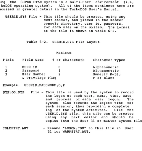
USERID.SYS File - This tile should be created, using any text editor, and placed in the master console directory, user id, password,
tor each user on the system. The tormat ot the tile is shown in Table 6-2.
Table 6-2. USERID.SYS File Layout
Maximum
Field Field Name
•
ot Characters Character Types1 USER ID 8 Alphanumeric
2 Password 8 Alphanumeric
3 User Number 2 Numer ,ic 0- 30 ,
& Privilage Flag P or blank Example: USERID,PASSWORD,O,P
SYSLOG .SYS
COLDSTRT.AUT
File - This tile is used by the system to record the logon ot each user, name, time, date and process ot each user logon. The system also records the logott time tor each session, thus providing a complete log ot the system activites. Like the USERID.SYS tile, this tile can be created using any text editor and should be
copied into the User 31 or master system tile. - Rename "LOGON.COM" to this tile in User
31 tor WARMSTRT.AUT.
[image:48.615.105.585.148.656.2]The Operating System
6.2.3 Helptul Hints When setting Up a TurboDOS Multi-User System (cont.)
WARMSTRT.AUT File - This tile is simply a tile with the
LOGON command copied into it. When this tile is present in the master system tile
(User 31), the system automatically
executes the LOGON command at system start-up and at the end ot each LOGOFF command
sequence. Simply copy the LOGOFF command into this tile and store it in the USER 31 system tile.
A sample dialog tor setting up your system with a user id tile: 1. Using a text editor create a tile called: USERID.SYS
2. Insert records tor each user, Examples: JIM,SAMPLE,O,P
SUSAN,MYFILE,IO,P
3. Copy the USERID,SYS tile to User 31 and LOGON.COM to WARMSTRT.AUT in User 31.
COpy USERID.SYS,D31
COpy LOGON.COM,WARMSTRT.AUT:D31
4. Edit the tile called SSLAVENBNK.PAR. Find the lable AUTOUSER and change as shown:
AUTOUSER
=
8~ ---) AUTOUSER=
OFF 5. Close this tile and enter the command:GEN SSLAVEBNK OSSLAVE.SYS
6.3 Basic Operating System Structure
The Operating System
6.3.1 CP/M
CP/M, Cont~ol Program tor Microprocessors, is the operating system which you will be using it you have a single-user SUPER STAR system. This operating system has been commersially available since 1975 and become a standard in the microcomputer
industry. It has been a wide variety ot disk management commands and usetul 1/0 commands tor the user. Because CP/M has become so popular there is an extencive library ot sottware, both business and scientitic available to you, the user. CP/M 2.2 is the standard operating system available with the SUPER STAR system, CP/M 3.0 are available as an option tor the SUPER STAR system.
6.3.2 TurboDOS
TurboDOS, like CP/M, is a computer operating system. TurboDOS is the system you will be using it you are going to operate the SUPER STAR system in a mUlti-user environment. This operating system is totally CP/M-compatable, thereby allowing you to load and execute any CP/M programs which you have developed. TurboDOS also provides increased disk storage capacity ot 25% to 35% over that ot the single user CP/M SUPER STAR system.
6.4 Single User System (CP/M 2.2)
The tollowing sections describe tunctions and the commandS that execute those tunctions using the CP/M 2.2 operating system. It you are currently using the CP/M 3.0 operating system skip to Section 6.7 tor the TurboDOS operating system.
6.4.1 Copying Hard Disk to Diskettes
This section d~scribes the procedure tor copying data trom the hard disk to ~-~loppy disk.
To COE~rthe hard disk to a diskette, proceed as tallows:
/
~~/ Power up the system it it is not already running. The /operating system is assumed to be currently loaded on the tixed // portion ot the hard diS'k drive.
2. Insert a tloppy disk you want to copy data into the tloppy disk drive it you have not already done so.
The
Operating
System6.4.1 Copying Hard Disk to Diskette (continued)
3. The logon message is displayed and the CP/M command prompt is displayed:
A) - Where A is the tixed disk. The system assigns A to the tixed disk when the system is booted trom the tixed disk. The system assigns the tloppy disk as drive C and cartridge disk as B.
4. Enter the command, FMT548. This command tormats the diskette currently installed in the tloppy disk drive. CP/M assigns the
tloppy disk drive C. A)FMT548 [RETURN]
Enter Disk Drive to be cormatted {0-3):0 Format Single or Double Sided (5,0):0 Format System Tracts only {Y:N):N Surpress Format Veritication (YiN):N
Insert Diskette Into Drive 0 and Press The Return Key
5. The system tormats the diskette installed in the tloppy disk drive and displayes the tollowing message:
Format complete
6. Use the PIP command to copy a l l o t the tiles trom your source diskette to the new one:
A)PIP C:=A:*.*[v] [RETURN] [v] - allows veritication
7. In order to assure that the copy was successtul, check both directories using the DIR command and compare them:
A)DIR A: [RETURN] A)DIR C:[RETURN]
The Operating System
6.4.2 Copying Hard Disk to Cartridge (continued)
6. In order to assure that the copy was successtul, check both directories using the DIR command and compare them:
A)DIR B:[RETURN] A)DIR A: [RETURN]
7. It you want to make the cartridge bootable use LDRGEN to write the track 0 loader:
A)LDRGEN TODMA5.LDR[RETURN]
Physical drive no. ot loader destination (0-3):0 Write loader to cartridge or tixed (C or F):C
This completes the copy procedure. Remove the copy and store this cartridge away in a sate location until i t is needed.
6.4.3 Copying Cartridge to Diskette
This section describes the procedure tor copying data trom the cartridge to the diskette drive.
To copy the cartridge disk, proceed as tollows:
1. Insert the cartridge to be copied into the hard disk drive i t you have not already done so.
2. Power up the hard drive by pressing the run button on the hard drive. Wait tor the run drive to come up to operating speed.
3. The logon message is displayed and the CP/M command is displayed:'
A) - Where A is the tixed disk. The system assigns A to the tixed disk when ·the system is booted trom the tixed disk. The systems assigns the tloppy disk as drive C and cartridge disk as B.
The Operating System
6.4.2 Copying Hard Disk to Cartridge
This section describes the procedure tor copying data trom the hard disk to a cartridge disk.
To·copy the hard disk to a cartridge, proceed as tollows:
1. Power up the system it it is not already running. The operating system is assumed to be currently loaded on the tixed portion ot the hard disk drive.
2. The logon message is displayed and the CP/M command is displayed:
A) - Where A is the tixed disk. The system assigns A to the tixed disk when the system is booted trom the tixed disk. The system assigns the tloppy disk as drive C and cartridge disk as B.
3. Enter the command, FMTHD. This command tormats the cartridge currently installed in the hard disk drive. CP/M assigns the cartridge disk drive B.
A)FMTHD [RETURN] [MENU DISPLAYED]
Enter drive to tormat: 20 (selection)
Do you want to tormat the Cartridge, Fixed or Both [C,F orB):C Which physical disk do you want to tormat (0-3)? 0
This operation will destroy all data on drive 0. Hit return to continue or Control-C to abort.
4. The system tormats the cartridge installed in the tixed disk drive and ~isplays the tollowing message;
Format complete
5. Erase any entries in the directory and use the PIP command to copy a l l o t the tiles trom your tixed disk to the cartridge:
The Operating System
6.4.3 Copying Cartridge to Diskette (continued)
4. Enter the command, FMT548. This command tormats the diskette currently installed in the tloppy disk drive. CP/M assigns the tloppy disk drive C.
A)FMT548 [RETURN]
Enter Disk Drive to be tormatted (0-3}:0 Format Single or Double Sided (S,D):D Format SYstem Tracts only (Y,N}:N Suppress Format Veritication (Y,N):N
Insert Diskette Into Drive 0 and Press The Return Key
5. The system tormats the diskette installed in the tloppy disk drive and displays the tollowing message:
Format complete
6. Copy the cartridge data to the tloppy disk using the PIP command:
A)PIP C:=B:*.*[v] [RETURN] [v] - allows veritication
7. When this is complete compare the two disk, master and new copy using the directory command, a l l o t the tiles trom the cartridge disk should now also be listed in the tloppy disk directory:
A)OIR B:[RETURN] A)DIR C:[RETURN]
This completes the copy procedure.
6.4.4 Copying Cartridge to Fixed Disk
This section describes the procedure tor copying data trom the cartridge to tixed portion ot the hard disk drive.
To copy the cartridge disk, proceed as tollows:
1. Insert the cartridge to be copied into the hard disk drive it you have not already done so.,