Apollo Computer Inc. 330 Billerica Road Chelmsford, MA 01824
Copyright © 1987 Apollo Computer Inc. All rights reserved. Printed in U.
s.
A. First Printing:Latest Printing:
July, 1985 January, 1987
This document was produced using the Interleaf Workstation Publishing Soft-ware (WPS). Interleaf and WPS are trademarks of Interleaf, Inc.
APOLLO and DOMAIN are registered trademarks of Apollo Computer Inc. AEGIS, DGR, DOMAIN/BRIDGE, DOMAIN/DFL-100, DOMAIN/DQC-100, DO-MAIN/Dialogue, DOMAIN/IX, DOMAIN/Laser-26, DOMAIN/PCI, DOMAIN/ SNA, D3M, DPSS, DSEE, GMR, and GPR are trademarks of Apollo Computer Inc.
Apollo Computer Inc. reserves the right to make changes In specifications and other Information contained In this publication without prior notice, and the reader should in all cases consult Apollo Computer Inc. to determine whether any such changes have been made.
THE TERMS AND CONDITIONS GOVERNING THE SALE OF APOLLO COM-PUTER INC. HARDWARE PRODUCTS AND THE LICENSING OF APOLLO COMPUTER INC. SOFTWARE CONSIST SOLELY OF THOSE SET FORTH IN THE WRITTEN CONTRACTS BETWEEN APOLLO COMPUTER INC. AND ITS CUSTOMERS. NO REPRESENTATION OR OTHER AFFIRMATION OF FACT CONTAINED IN THIS PUBLICATION, INCLUDING BUT NOT LIMITED TO STATEMENTS REGARDING CAPACITY , RESPONSE-TIME PERFORMANCE, SUITABILITY FOR USE OR PERFORMANCE OF PRODUCTS DESCRIBED HEREIN SHALL BE DEEMED TO BE A WARRANTY BY APOLLO COMPUTER INC. FOR ANY PURPOSE, OR GIVE RISE TO ANY LIABILITY BY APOLLO COMPUTER INC. WHATSOEVER.
The DOMAIN® System User's Guide is the second volume in the two-volume introduction to the DOMAIN® (Distributed On-line Multi-Access Interactive Network) Computing System. The first volume, Getting Started With Your DOMAIN System, introduces you to the basic concepts you'll need to use the DOMAIN system on your node. The DOMAIN System User's Guide follows with more detailed information about the system and describes how to use the system to perform various computing tasks.
The Organization of this Manual
We've divided this manual into three separate parts, each part describing a set of related topics. Part I describes the DOMAIN sys-tem. Part II and Part III describe how to perform various tasks using system commands and utilities. We've separated each part with a tabbed divider for easy access.
Chapter 1
Chapter 2
Provides an overview of the DOMAIN sys-tem and its distributed operating environ-ment. It describes how the system organizes objects in the system naming tree, and how to use pathnames to identify these objects.
-- The
Chapter 3
Chapter 4
Chapter 5
III
Chapter 6
Chapter 7
Chapter 8
Chapter 9
Environment
Explains the functions of the Display Manager (DM), describes how to use DM commands, and shows how to define keys to perform DM functions.
Describes how to use the DM to control your node's display. Each section describes a set of related display management tasks and the DM commands you use to perform them.
Describes how to use the DM to control the characteristics of edit pads and how to edit text. Each section in this chapter describes a set of editing tasks and the DM commands you use to perform them .
... V J I U . . . " " . . I\Ul Shell
Describes the command Shell environment that processes Shell commands. The chapter includes information on: Shell commands, controlling command input and output, the command line parser, and using pathname wildcards.
Describes how to use Shell commands to manage files, directories, and links on the system.
Describes Access Control Lists (ACLs) and how to use them to control access to files and directories.
Documentation Conventions
Unless otherwise noted in the text, this manual uses the following symbolic conventions.
UPPERCASE
lowercase
output
Bolded term or key
{ }
< >
Bold, uppercase words or characters in for-mats and command descriptions represent commands or keywords that you must use literally.
Bold, lowercase words or characters in for-mats and command descriptions represent values that you must supply.
Color words in command examples represent literal user keyboard input.
System output in command examples ap-pears in this font.
When new terms or keys are introduced, they appear in boldface.
Square brackets enclose optional items in formats and command descriptions. In sample Pascal statements, square brackets assume their Pascal meanings.
Braces enclose a list from which you must choose an item in formats and command descriptions. In sample Pascal statements, braces assume their Pascal meanings.
A vertical bar separates items in a list of choices.
CTRLI The notation CTRLI followed by the name of a key indicates a control character se-quence. You should hold down <CTRL> while typing the character.
Horizontal ellipsis points indicate that the preceding item can be repeated one or more times.
Vertical ellipsis points mean that irrelevant parts of a figure or example have been omit-ted.
Related Manuals
If you are using the DOMAIN system for the first time, you should read Getting Started With Your DOMAIN System (order number 002348) first. Getting Started With Your DOMAIN System teaches you the basics of using the DOMAIN system.
The DOMAIN System Command Reference (order number 002547) contains detailed descriptions of all DOMAIN system commands. The command descriptions are arranged alphabetically for quick and easy access.
For information on how to create the network environment, protect the network software, create servers, and maintain and troubleshoot the network, see Administering Your DOMAIN System (Order num-ber 001746).
Problems, Questions, and Suggestions
We appreciate comments from the people who use our system. In order to make it easy for you to communicate with us, we provide the Vser Change Request (VCR) system for software-related comments, and the Reader's Response form for documentation comments. By using these formal channels you make it easy for us to respond to your comments.
CRUCR (Create User Change Request) Shell command description. You can view the same description on-line by typing:
$
For your documentation comments, we've included a Reader's Response form at the back of each manual.
Using the Stand-Up Binder
Chapter 1 The DOMAIN System
Overview . . . 1-2 The Naming Tree . . . 1-4 Using Pathnames . . . 1-6 The Working Directory . . . 1-9 The Naming Directory . . . 1-11 The Parent Directory . . . 1-12 Pathname Summary . . . 1-13
Chapter 2 Start-Up and Log-In
Understanding the System at Start-Up ... 2-2 Disked Node Start-Up . . . 2-2 Diskless Node Start-Up . . . 2-8 Understanding the System at Log-In ... 2-13 Logging In . . . 2-20 Logging In as User . . . 2-20 Changing Your Password . . . 2-20 Changing Your Home Directory . . . 2-21 Logging Into a DOMAIN Server Processor (DSP) ... 2-22
Chapter 3 Using The Display Manager
Using DM Commands . . . 3-2 DM Command Conventions . . . 3-4 Defining Points and Regions . . . 3-6
Controlling Keys from Within a Program ... 3-21 Using DM Command Scripts . . . 3-22
Chapter 4 Controlling the Display
Controlling Cursor Movement . . . 4-2 Creating Processes . . . 4-4 Creating a Process with Pads and Windows ... 4-5 Creating a Process without Pads and Windows ... 4-7 Creating a Server Process . . . 4-8 Controlling a Process . . . 4-8 Stopping a Program or Process . . . 4-9 Suspending and Resuming a Process . . . 4-10
Chapter S Editing a Pad
Setting Edit Pad Modes . . . 5-2 Setting Read/Write Mode . . . 5 - 3 Setting Insert/Overstrike Mode . . . 5-4
Inserting Characters . . . 5-4 Inserting a Text String . . . 5-5 Inserting a NEWLINE Character . . . 5-5 Inserting a New Line . . . 5-6 Inserting an End-of-File Mark . . . 5-6
Deleting Text . . . 5-6 Deleting Characters . . . 5-7 Deleting Words . . . 5-7 Deleting Lines . . . 5-8
Defining a Range of Text . . . 5-9
Copying, Cutting, and Pasting Text . . . 5-10 Using Paste Buffers . . . 5-11 Copying Text . . . 5-12 Copying a Display Image . . . 5-13 Cutting Text . . . 5-14 Pasting Text . . . 5-15
U sing Regular Expressions . . . 5 -16
Searching for Text . . . 5-23 Repeating a Search Operation . . . 5-25 Cancelling a Search Operation . . . 5-25 Setting Case Comparison . . . 5-25
Substituting Text . . . 5-26 Substituting All Occurrences of a String . . . 5 - 27 Substituting the First Occurrence of a String . . . 5 - 28 Changing the Case of Letters . . . 5 - 28
Undoing Previous Commands . . . 5-29
Updating an Edit File . . . 5-29
Chapter 6 U sing the Shell
Command Search Rules . . . 6-5 Special Characters . . . 6-7 Creating and Invoking Shells . . . 6-7 Setting Up the Initial Shell Environment ... 6-8 Controlling Input and Output . . . 6-9 Reading Input from a File . . . 6-11 Writing Output to a File . . . 6-12 Appending Output to a File . . . 6-12 Redirecting Ouput to Other Commands ... 6-13 The Command Line Parser . . . 6-14 Using Query Options . . . 6-15 Reading Data from Standard Input . . . 6-16 Reading Pathnames from Standard Input ... 6-17 Using Pathname Wildcards . . . 6-18 Running Programs in a Background Process ... 6-22
Chapter 7 Managing Files, Directories, and Links
Displaying Directory Information . . . 7-28 Deleting Directory Trees . . . 7-30
Managing Links . . . 7-31 Creating Links . . . 7-32 Displaying Link Resolution Names . . . 7-33 Redefining Links . . . 7-33 Renaming Links . . . 7-34 Copying Links . . . .. 7-35 Deleting Links . . . 7-36
Chapter 8 Controlling Access to Files and Directories
ACL Structure . . . 8-2 The Subject Identifier (SID) . . . 8-3 Access Rights . . . 8-4 Understanding SEARCH and EXPUNGE Rights ... 8-7 Managing ACLs . . . 8-7
Displaying ACLs . . . 8-8
Editing ACLs . . . 8-9 Rules to Specify ACL Entries . . . 8-11 Adding ACL Entries . . . 8-15 Changing Entry Rights . . . 8 -15 Adding Entry Rights . . . 8-16 Deleting Entry Rights . . . 8-17 Deleting ACL Entries . . . 8-17
Copying ACLs . . . 8-18
Initial ACLs . . . 8-18 Editing Initial ACLs . . . 8-20 Copying Initial ACLs . . . 8-21
Chapter 9 Writing Shell Scripts
Creating Your Own Commands . . . 9-2 Creating Scripts . . . 9-2 Passing Arguments to Scripts . . . 9-4 Using Quoted Strings . . . 9-8 Using In-Line Data . . . 9-9 Executing DM Commands from Shell Scripts ... 9.-10 Debugging Shell Scripts . . . 9-10 Using Expressions . . . .. 9 -12 Operands in Expressions . . . 9-14 Mathematical Operators . . . 9-14 String Operators . . . 9-15 Comparison Operators . . . 9-16 Logical Operators . . . 9-17 Shell Variables . . . 9-18 Defining Variables . . . 9-18 Using Shell Variables . . . 9-19 Variable Commands . . . 9-21 Defining Variables Interactively . . . 9-22 Using Active Functions . . . 9-24 Controlling Script Execution . . . 9-25 Using the IF Statement . . . 9-28 Using the WHILE Statement . . . 9-29 Using the FOR Statement . . . 9-31 Using the SELECT Statement . . . 9-34
Appendix A Initial Directory and File Structure
Appendix B Summary of Predefined Key Definitions
Illustrations
Figure Page
1-1 A Simple DOMAIN Network . . . 1-2
1-2 A Sample Naming Tree ... . . 1-4
1-3 A Sample Path Through the Naming Tree ... 1-7
1-4 A Sample Path Beginning at the Node Entry
Directory . . . 1-8
1-5 A Sample Path Beginning at the Current
Working Directory . . . 1-10
1-6 A Sample Path Beginning at the Current
Naming Directory . . . 1-12
1-7 A Sample Path Beginning at the Parent
Directory . . . 1-13
2-1 The Start-Up Sequence for Disked Nodes ... 2-3
2-2 A Sample Boot Script (STARTUP.19L) . . . 2-6
2-3 The Start-Up Sequence for a Diskless Node ... 2-9
2-4 The Boot Script Search Sequence . . . 2-13
2-5 The Log-In Sequence . . . 2-14
2-6 A Sample Log-In Start-Up Script
(STARTUP_LOGIN. 19L) . . . 2-17
2-7 A Sample DM Start-Up Script
(STARTUP_DM.19L) . . . 2-19
3-1 Invoking a DM Command Interactively . . . 3-3
3-2 Defining a Display Region . . . 3-9
3-3 Key Names for the Low-Profile Type
Keyboards . . . 3-13
4-1 A Process Running the Shell . . . 4-6
4-2 Creating an Edit Pad and Window . . . 4-13
4-3 Copying a Pad and Window . . . 4-15
4-4 Growing a Window Using Rubberbanding ... 4-19
4-6 Process Window Legend . . . 4-23
4-7 Location of Pad Scroll Keys . . . 4-29
4-8 Default Icon for Shell Process Windows ... 4-34
5-1 The Edit Pad Window Legend . . . 5-3
5-2 Defining a Range of Text with <MARK> ... 5-10
5-3 Copying Text with the XC -R Command ... 5-13
6-1 The Shell Process . . . 6-2
6-2 Shell Command Line Components . . . 6-3
6-3 Sample Shell Start-Up Script . . . 6-9
7-1 The Print Menu . . . 7-13
7-2 Print "Commands" Submenu . . . 7-15
7-3 Sample Display Showing File Attributes ... 7-17
7-4 Comparing Two ASCII Files . . . 7-19
7-5 Sample Directory Tree . . . 7-23
7-6 Copying a Directory Tree . . . 7-24
7-7 Replacing a Directory Tree . . . 7-25
7-8 Comparing Directory Trees . . . 7-28
7-9 Sample Directory Display . . . 7-29
7-10 Deleting a Directory Tree . . . 7-30
7-11 Sample Display of Link Resolution Names ... 7-33
8-1 Structure of an ACL Entry . . . 8-2
8-2 Sample ACL Entries . . . 8-3
8-3 Sample ACL Display . . . 8-8
8-4 Initial ACLs for Files and Directories . . . 8-19
8-5 Controlling Access to Protected Subsystem Files .. 8-24
8-6 Sample of a Protected Subsystem Transcript ... 8-28
9-1 Including In-Line Data in a Script . . . 9-9
9-2 A Sample Script Using the READ Command .... 9-23
9-3 Flow of Execution in a Simple Script . . . 9-26
9-4 Flow of Execution with a Conditional Statement .. 9-27
A -1 The Node Entry Directory (I) and Subdirectories . A - 2
A-3 A-4
B-1
The Display Manager Directory (lSYS/DM) ... A-4 The Network Management Directory (lSYS/NET) A-5
Table
1-1
2-1 2-23-1
3-23-3
3-4
3-54-1
4-24-3
4-4
4-5 4-6 4-7 4-8 4-94-10
4-11
5-1
5-2
5-3 5-45-5
5-6
5-7 6-1Tables
PagePathname Symbols . . . 1-9 Node Boot Script Files . . . 2-5 Node Log-In Start-Up Script Files ... 2-16
Rules for Using DM Special Characters ... 3-5 Formats for Specifying Points on the Display ... 3-7 Default Mouse Key Functions . . . 3-11 Key Definition File Names . . . 3-14
Key Naming Conventions . . . 3-16 Cursor Control Commands . . . 4-2 Commands for Creating Processes ... 4-5 Commands for Controlling a Process ... 4-9 Commands for Creating Pads and Windows ... 4-10 DM Rules for Defining Window Boundaries ... 4-11
Commands for Closing Pads and Windows ... 4-16 Commands for Managing Windows ... 4-18 Process Window Modes . . . 4-23 Commands for Moving Pads . . . 4-27 Commands for Controlling Window Groups and
Icons . . . 4-31
Window Paste Buffers . . . 4-38 Commands for Setting Edit Modes ... 5-2 Commands for Inserting Characters ... 5-5
Commands for Deleting Text . . . 5-7 Commands for Copying, Cutting, and Pasting
6-2 I/O Control Characters . . . 6-11
6-3 Command Line Parser Options . . . 6-15
6-4 Command Query Responses . . . 6-16 6-5 Summary of Pathname Wildcards ... 6-19 7-1 Commands for Setting the Working and Naming
Directory . . . 7 - 2 7-2 Commands for Managing Files . . . 7-5 7-3 Print "Commands" Submenu Items ... 7-16 7-4 Commands for Managing Directories ... 7-20 7-5 Commands for Managing Links . . . 7-31
8-1 Access Rights for Files and Directories ... 8-6 8-2 Summary of Commands for Editing ACLs ... 8-10 8-3 Valid Rights for Files and Directories ... 8-12 8-4 Class Names for Commonly Assigned Rights ... 8-14 8-5 Summary of Commands for Editing and Copying
Initial ACLs . . . 8-20 8-6 Options for Copying Initial ACLs ... 8-22 9-1 Shell Parsing Operators . . . 9-3 9-2 Script Verification Options . . . 9-11
The DOMAIN system is a high-speed communications network con-necting two or more of our computers, called nodes. Each node loads programs into its own memory, and uses the computing func-tions of its own central processing unit (CPU) . Because the DOMAIN system enables nodes to share information, you can log into any node and access information stored anywhere in the net-work.
Many of the operations you'll perform on the system involve the use of objects (files, directories, and links) that store information such as programs, data, or text. Before you can work with these objects, you must understand how the system organizes and identifies them.
The DOMAIN system uses a physical network, in which member nodes can load data from the network into memory just as they would load data from their own disk.
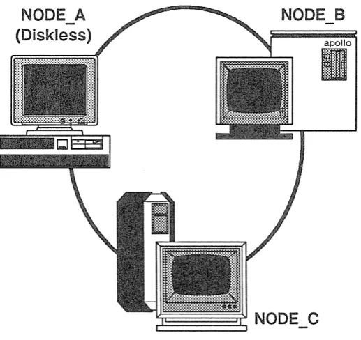
[image:21.421.71.330.200.444.2]The DOMAIN System Site Planning and Preparation Guide describes the DOMAIN network in much more detail. For our pur-poses, we're interested in the network to see how nodes use the sys-tem to share information. Figure 1-1 shows a simple DOMAIN net-work composed of three nodes and two disks.
The DOMAIN system makes the information on all disks available to any node in the DOMAIN network. For example, in Figure 1-1,
NODE_C can access information stored on its own disk, as well as
information stored on the disk connected to NODEJ3. Although
NODE_A doesn't have its own disk, it can, via the network, access
information stored on the disks connected to NODE_B or NODE_C.
Each node in the network requires the use of at least one disk, called a boot volume, that contains the operating system and other system software it needs to run. Some nodes, called disked nodes, are physically connected to the disk that they use as the boot volume. Other nodes, called diskless nodes, share the boot volume of some other disked node in the network, called a network partner. In Figure 1-1, NODE_B and NODE_C are disked nodes. Because
NODE_A is a diskless node, it must use either NODE_B or NODE_C
as its partner.
To run in the network, a diskless node must have a network partner. The network partner's disk provides all of the necessary operating system and support software for the diskless node. Because a disk-less node relies on its partner for system software, it can operate only when the partner node is operating. If the partner node is removed from the network while the diskless node is running, the diskless node will crash.
The operating system interface on each node, whether disked or diskless, is made up of two main programs: the Display Manager
(DM) and the Shell.
The DM is the system program that controls your node's display and enables you to create processes. The DM listens for DM commands that you specify in the DM command input pad of your display. Part II of this manual describes your node's display environment and how to use the DM to control this environment.
The Naming Tree
To make information available to all the nodes in the network, the DOMAIN system organizes objects in a hierarchical structure called a naming tree. The naming tree serves as a type of map that the sys-tem uses to keep track of where objects reside in the network. To access an object, you refer to its location in the naming tree. Figure 1-2 shows a sample naming tree.
Figure 1-2. A Sample Naming Tree
[image:23.422.41.354.149.408.2]network root directory containing the names of two node entry direc-tories: NODE_B and NODE_C.
Each disked node in the network has a node entry directory name associated with it. This name refers to the branch of the naming tree that resides on its disk. (Since diskless nodes don't have disks, they use the node entry directory of their partner.) In Figure 1-2, all of the objects under the node entry directory, NODE_B, reside on the disk NODE_B, while all of the objects under the node entry direc-tory NODE_C reside on the disk NODE_C. In other words, each disk in the network represents an entry directory in the system naming tree.
Entry directories contain one or more upper-level directories. An upper-level directory is one level below the entry directory and nor-mally serves as the main directory for a branch of logically related objects. For example, the /SYS directory that we supply is an upper-level directory that contains many of the system objects that make up the operating system. (Appendix A contains a set of figures that il-lustrate how the system organizes the software we supply with your node.) An upper-level directory can also serve as a user's main directory for storing files.
In Figure 1-2, the directories OWNER and USER_l are upper-level directories, one level below the entry directory NODE_B. The direc-tory OWNER serves as the main direcdirec-tory for all objects that belong to the owner of the node. The upper-level directory USER_l is the main directory for the user of a diskless node (NODE_A) that uses
NODE_B as its entry directory. The directory USER serves as the
main directory for the user on NODE _C.
In summary, the network root directory contains the names of node entry directories in the network. The system uses your node's net-work root directory to determine which node entry directories in the network it can access. Each node entry directory contains one or more upper-level directories. An upper-level directory serves as the main directory for logically related objects.
(CATALOG_NODE) described in the DOMAIN System Command Reference.
Some network sites use the NS_HELPER (Naming Server Helper) to maintain an up-to-date network root directory. If your site uses NS_HELPER, you don't need to use CTNODE to catalog nodes; NS_HELPER does it for you. To find out if your network site uses the NS_HELPER, ask your system administrator. Administering Your DOMAIN System describes NS_HELPER and explains how to catalog nodes to update the network root directory.
The system identifies each object in the naming tree by its unique location. Whenever you specify a command to create or access an object, you also specify a pathname that points to the object's loca-tion in the naming tree. The pathname tells the system what path to follow when searching for an object.
The commands you use to create and manage objects require you to specify a pathname as a command argument. When you invoke a command, the command specifies the operation, and the pathname tells the system where in the naming tree to perform it.
For example, the following Shell command deletes the file MEMO in the naming tree shown in Figure 1-3 :
$ DLF
T
command
IINODE_B/USER_1/MEMO I
pathname
The pathname directs the system to:
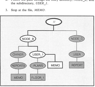
1. Start at the network root directory (! /) .
2. Follow the path through the entry directory, NODEJj, and the subdirectory, USER_I.
[image:26.421.65.380.96.381.2]3. Stop at the file, MEMO.
Figure 1-3. A Sample Path Through the Naming Tree
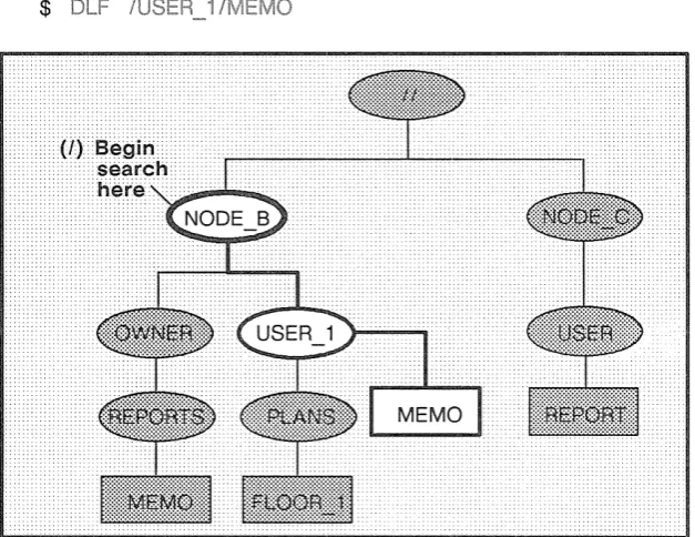
You don't have to begin pathnames with the network root directory specification. For example, the single slash (I) symbol directs the system to begin its search at your node's entry directory. Here is an example using the single slash to start a search at your node's entry directory:
$
Figure 1-4. A Sample Path Beginning at the Node Entry Directory
For this example, let's assume that your node's entry directory is
NODE B. As shown in Figure 1-4, the pathname directs the system
to:
1. Start at your node's entry directory, NODE_B.
2. Follow the path through the upper-level directory, USER_i.
[image:27.421.41.355.92.334.2]You can specify other starting points in the naming tree by beginning a pathname with any of the symbols in Table 1-1.
Table 1-1. Pathname Symbols
Symbol System starts search at:
II
Network root directory/
N ode entry directoryNo symbol or • Working directory
-
Naming directory\
Parent directoryThe Working Directory
If you specify a pathname without a symbol preceding it (or if you precede the pathname with a period) the system starts its search at a default location in the naming tree called the working directory. Think of the working directory as the directory location in which you are currently working. Each process that you create uses one of the directories in the naming tree as its working directory.
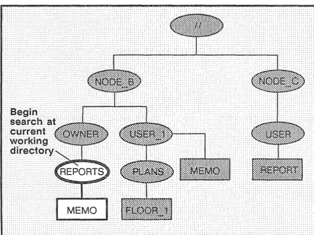
The following command deletes the file MEMO in the current work-ing directory:
$
In this example, let's assume that the current working directory is the directory REPORTS. As shown in Figure 1-5, the system begins its search at REPORTS and deletes the file MEMO.
Figure 1-5. A Sample Path Beginning at the Current Working Directory
[image:29.425.43.356.134.368.2]The Naming Directory
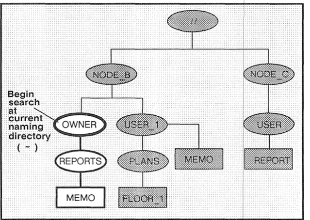
If you precede a pathname with the tilde ( ,., ) symbol, the system starts its search at a location in the naming tree called the naming directory. Like the working directory, each process has a naming directory that points to some directory in the naming tree.
When you log into a node, the system creates a process running the Shell program and sets that process's naming directory to the home directory name designated in your user account. The system uses this directory as your naming directory unless you change it to another directory. (Chapter 7 describes how to change your naming directory. )
The following command deletes the file MEMO in the current naming directory:
$ DLF -REPORTS/MEMO
In this example, let's assume that the current naming directory is the upper-level directory OWNER. As shown in Figure 1-6, the path-name directs the system to:
1. Start at your node's naming directory, OWNER. 2. Follow the path through the directory, REPORTS.
3. Stop at the file, MEMO.
Figure 1-6. A Sample Path Beginning at the Curr~nt Naming Directory
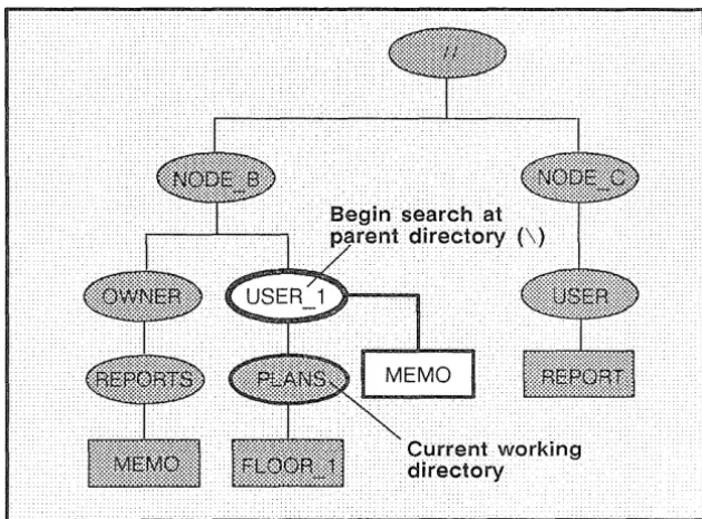
The Parent Directory
If you precede the pathname with a backslash (\) symDol, the system starts its search at a location called the parent
directJ~ry.
A parent directory is the directory one level above the current rorking direc-tory. For example, the following command uses th¢ \ symbol to delete the file MEMO in the directory USER_1:$
Figure 1-7. A Sample Path Beginning at the Parent Directory
Pathname Summary
In this section, you learned how to use pathnames to point to objects in the system naming tree. The examples showed you how to use pathnames with commands to tell the system the naming tree location where you want a particular operation performed.
[image:32.425.59.374.46.279.2]I
Each time you start up a node and log in to it, the DOMAIN system executes various programs that start the operating system, and scripts that set up the node's operating environment. You can tailor the operating environment on your node by modifying the scripts the sys-tem uses at start-up and log-in. For example, you may want to start specific server processes when you start up your node. Or, you may want your own specific key definitions, default window positions, and tabs defined each time you log in.
This chapter describes how the system functions at start-up and in, and describes the steps you can take to tailor your
vironment. The chapter also describes for vJ.iU.UF,.1.1.JLF,
The Owner's Guide for your node describes the proper procedure for starting it up. When you initiate the node's start-up by turning on the power, the node performs a series of operations to boot the operating system (load the operating system from disk into memory) and begin executing it. The operating system then executes a series of start-up files to set up the operating environment on your node.
This section explains the sequence of events occurring at start-up for both disked and diskless nodes.
Disked Node Start-Up
Figure 2-1. The Start-Up Sequence for Oisked Nodes
The descriptions that follow explain each step in the start-up se-quence shown in Figure 2-1.
resides in the node's boot PROM (Programmable Read-Only Memory).
2. The MD reads a program called SYSBOOT from your node's disk and loads it into the CPU's memory. The MD then transfers control to SYSBOOT. SYSBOOT, as its name indicates, is the program responsible for booting the operat-ing system.
3. The SYSBOOT program loads the operating system into the CPU's memory. Once loaded, the operating system begins executing and takes control.
4. The operating system starts either:
• The Display Manager (DM) on nodes with displays.
• The Server Process Manager on DOMAIN Server Processors (DSPs). The SPM is the server program that allows you to create a process on a DSP from a remote node in the network. (For more informa-tion about the SPM, see Administering Your DOMAIN System.)
5. The DM or the SPM executes a start-up file, called a boot that sets up the initial operating environment on your node. Table 2-1 lists the different boot script files used at start-up. As shown in Table 2-1, the system chooses which boot script file to execute according to the type of node.
All of the boot script files listed in Table 2-1 reside in the directory 'NODE_DATA. The grave accent (') that precedes the directory name is a special symbol that returns a value for . For example, on disked nodes,
'NODE_DATA points to the directory ISYSINODE_DATA
on the node's disk. On diskless
less Node
to the
Table 2-1. Node Boot Script Files
Node Type Boot Script Filename
800xl024 (Portrait) STARTUP
DN400
l024x800 (Landscape) STARTUP .19L DN420, DN460, DN3xx,
DN550, DN560, DN570, DN3000 (Color)
1280xlO24 STARTUP . 1280COLOR
(Color Landscape)
DN580
1280xlO24 STARTUP. 1280BW
(Black & White Landscape) DN3000 (Black & White)
l024xl024 (Color) STARTUP.COLOR DN600
Displayless STARTUP.SPM
DOMAIN Server Processors (DSPs)
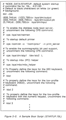
[image:38.421.100.376.66.395.2]# 'NODE_DATA/STARTUP, default system startup # command file for 19L, 4/21/83
# Default is black, characters on white (or green) # background.
INV -ON
(608,744)dr; (1023, 799)cv /sys/dm/output (556,744)dr; (608,799)cv /sys/dm/output;pb (0,744)dr; (556,799)cv /sys/dm/input
# To enable the diskless node boot server, # uncomment the following CPS command. #
# cps /sys/net/netman # To startup default printer #
# cps /com/sh -c '/com/prsvr' -n print_server # To enable the summagraphic bit pad support, # uncomment the following CPS command. #
# cps /sys/dm/sbp1 /dev/sio2 L # To startup mbx (IPC) helper #
# cps /sys/mbx/mbx_helper
# To Properly define the keys for the 880 keyboard, # uncomment the following command.
# # kbd
# To properly define the keys for the low-profile # keyboard (KBD2), uncomment the following # command.
#
# kbd 2
# To properly defin,f3 the keys for the low-profile # keyboard with the numeric keypad, uncomment the # following command.
#
# kbd 3
[image:39.422.78.354.23.524.2]III II
The boot script contains commands that start various server programs. These server programs run regardless of log-in and log-out activity and provide various system services to the node. For example, the NETMAN program makes the node available as a host for diskless partners, and the print server program (PRSVR) runs peripheral printers. For a description of these and all of the DOMAIN server programs, see Administering Your DOMAIN System.
If you want your node to automatically start any of these server programs, edit your node's boot script and remove the pound sign (#) from the command line that invokes the serv-er. Note, however, that the system will not start any of these servers until the next time you shut down and restart your node. (See your node's Owner's Guide for node startup and shutdown procedures.)
The boot scripts that run on nodes that have displays contain a set of commands that instruct the Display Manager to draw the initial display windows on the screen. One of the win-dows contains the "Please log in:" prompt.
These boot scripts also contain commands that specify which type of keyboard the node is using. If your node uses the DOMAIN Low-profile Model I keyboard, remove the # from the KBD2 command. If your node uses the low-profile keyboard with the numeric keypad (DOMAIN Low-profile Model II keyboard), remove the # from the KBD3 com-mand. See the "Using Keys to Perform DM Functions" sec-tion in Chapter 3 for a descripsec-tion of keyboard types.
Note: On DN3000 nodes, use of the KBD 3 command is optional; KBD 3 is assumed by default.
The STARTUP.SPM script used by DSPs is similar to the other start-up scripts. However, since DSPs don't have dis-plays, STARTUP.SPM doesn't contain commands for creat-ing windows.
The start-up sequence for diskless nodes is somewhat different than the start-up sequence for disked nodes. A diskless node does not have its own disk to store the operating system and other software files it needs to run. Therefore, each time it starts up, the diskless node must load parts of the operating system across the network from its partner node. The diskless node also relies on its partner for any utility programs and libraries it needs. Figure 2-3 presents a flowchart showing the start-up sequence for a diskless node.
1. When you power on your node in NORMAL mode (by fol-lowing the instructions in your Owner's Guide), a program called the Mnemonic Debugger (MD) begins executing. The MD resides in the node's boot PROM (Programmable Read-Only Memory).
2. Because a diskless node does not have a disk, the MD can-not load SYSBOOT and transfer control to it. Instead, the MD must boot the system from another disked node in the network. The MD then broadcasts a message across the net-work asking for a partner node to volunteer the use of its boot volume.
3. All nodes running the NETMAN program receive these re-quest messages (NETMAN's purpose is to respond to them). In response to the diskless node's request, NETMAN on a disked node checks the file ISYSINETIDISKLESS_LIST. This file on the disked node contains a list of hexadecimal node IDs for all nodes the disked node may offer partner-ship.
If the diskless list contains the ID of the diskless node re-questing partnership, NETMAN volunteers the node as a partner. The first disked node to volunteer becomes the partner of the diskless node. (It remains the diskless node's partner until the next time the diskless node boots.) At this point, the diskless node displays the partner node's node ID for your information.
You can take a look at a sample diskless list by reading the file ISYSINETISAMPLE_DISKLESS_LIST. For a complete description of how to create a diskless list and set up partners for diskless nodes, see Administering Your DOMAIN System.
network. The MD, when finished loading NETBOOT, trans-fers control to it.
5. The NETBOOT program, running on the diskless node, loads the operating system from the partner node's boot volume into memory.
6. The operating system starts either:
• The Display Manager (DM) on nodes with displays.
• The Server Process Manager (SPM) on DOMAIN Serv-er Processors (DSPs). The SPM is the sServ-ervServ-er program that allows you to create a process on a DSP from a remote node in the network. (Refer to Administering
Your DOMAIN System for more information about the
SPM.)
7. The DM or the SPM executes a start-up file, called a boot script, that sets up the initial operating environment on your node. Table 2-1 lists the different boot script files used at start-up. As shown in Table 2-1, the system chooses which boot script file to execute according to the type of node.
Since diskless nodes don't have files of their own, the DM or SPM must look to the partner node to find its boot script file. Just as on a disked node, the DM or SPM on a diskless node searches for the boot script file in the directory
'NODE_DATA. (The grave accent (') that precedes the directory name is a special symbol that returns a value for
NODE_DATA.) Unlike a disked node, however,
'NODE_DATA for the diskless node points to the directory ISYSINODE_DATA.node-id on the partner's disk. (The
node-id suffix is the hexadecimal node ID of your diskless
node.)
Once the DM or SPM finds the diskless node's boot script, the boot script executes. Figure 2-2 shows a sample boot script similar to the one we provide with DN3xx nodes. For information about this script refer to the "Understanding the System at Log-In" section.
"node-specific" boot script to set up its own unique operat-ing environment. Therefore, the system uses the node-id suffix to denote a unique boot script location for each disk-less node assigned to the partner.
At start-up, if the partner does not have a NODE DATA
directory set up for the diskless node, NETMAN creates one, copying it from a template stored in the partner's
'NODE_DATA directory. The NETMAN program then copies the partner node's boot script file into the diskless node's 'NODEYATA directory. If you want the newly created boot script to perform different operations at start-up than its partner, edit the boot script.
8. Once the boot script finishes executing, the node start-up completes, and the system prompts you to log in.
Figure 2-4. The Boot Script Search Sequence
en-vironment. The flowchart in Figure 2-5 shows the log-in sequence for a node.
The descriptions that follow explain each step in the log-in sequence shown in Figure 2-5.
1. After you enter your username and password, the operating system verifies your account. (Chapter 1 in Getting Started With Your DOMAIN System describes how to log in.)
The system verifies your account by checking the file AC-COUNT in the site registry directory. If the username and password match a valid account in the ACCOUNT file, the system executes the next step. If the system cannot verify the account, the log-in attempt fails, and the system displays a log-in error message in the DM output window. For more information about user accounts and registries, see Adminis-tering Your DOMAIN System.
2. The system sets your initial working directory and naming directory to the log-in home directory designated in your user account. You can change your log-in home directory anytime you log in. (See the "Changing Your Home Direc-tory" section later in this chapter.)
3. The DM (on nodes with displays) executes the node's log-in start-up script, which resides in one of the files listed in Table 2-2. As shown in Table 2-2, the system chooses which log-in start-up file to execute according to the type of node you are using. Note that on DSPs, the SPM does not execute a log-in start-up file.
Table 2-2. Node Log-In Start-Up Script Files
Node Type Boot Script Filename
800xlO24 (Portrait) STARTUP_LOGIN
DN400
l024x800 (Landscape) STARTUP_LOGIN.19L
DN420, DN460, DN3xx, DN550, DN560, DN570, DN3000 (Color)
1280xlO24 STARTUP_LOGIN. 1280COLOR
(Color Landscape) DN580
1280xl024 (B & W STARTUP_LOGIN. 1280BW
Landscape)
DN3000 (Black & White)
l024xl024 (Color) STARTUP_LOGIN. COLOR
DN600
You may want to create a log-in start-up script in
'NODE_DATA in cases where you don't want the DM to ex-ecute the default version. For example, a diskless node, by default, uses one of the log-in start-up scripts located in its partner's ISYSIDM directory. If you want the diskless node to execute its own unique log-in start-up script, you can create a copy in the diskless node's 'NODE _DATA direc-tory. For more information about 'NODE_DATA for diskless nodes, refer back to the "Diskless Node
section.
[image:49.425.85.361.57.330.2]When you log out, the DM stops the Shell process and deletes its pads and windows from the display. Figure 2-6 shows a sample log-in start-up script that we supply for DN300 nodes.
# STARTUP_LOGIN (the per_login startup file in # 'node_data or Isys/dm)
# main shell whose shape is generally agreeable to # users of this node
(0,300)dr; (700,700)cp Icom/sh
[image:50.423.96.375.89.348.2]## and the user's private dm command file from his # home directory's user_data sub-directory. Personal # key_defs file is also kept in user_data by OM. # cmdf user_data/startup_dm.19L
Figure 2-6. A Sample Log-In Start-Up Script (STARTUP _LOGIN. 19L)
As shown in Figure 2-6, the command that creates the initial Shell process is the only command not commented out in the script. You may leave it in, comment it out by adding the pound sign character (#), or change it to draw the process's windows in a different location. You can also add com-mands that will start certain processes that you want to run each time you log in.
You'll notice that the last line in the sample script shown in Figure 2-6 contains the DM command CMDF (COM-MAND _FILE) . This command invokes another script,
STARTUP _DM.19L. If you remove the # character from
the DM will not attempt to execute the script until the next time you log in.)
4. If no # character precedes the CMDF command line, the DM looks in the USER_DATA subdirectory of your log-in home directory for the specified file. If the DM finds the file, it executes the script; otherwise, it displays an error mes-sage in the DM output window when the log-in sequence completes.
This script, called the DM start-up script, is an optional script that you create to execute additional DM commands during log-in. For example, you may want to include com-mands that make specific key definitions or run specific programs. Figure 2-7 shows a sample DM start-up script.
# USER_DATA/STARTUP _DM (in login home directory) # Some personal preference keys:
#
# Define < F4 > and < F5 > for easy PASCAL # indenting and undenting:
#
KD F4 T1 ;S/% // KE KD F5 T1 ;S/%I 1 KE #
# Define CTRLI J to repeat previous substitution: #
KD "J S KE #
# Set tab every 5 spaces: #
TS 5 - R #
# Build a Shell window and execute a personal Shell # program
#
[image:52.422.98.368.45.330.2](0,500)dr; (799,955) cp Icom/sh -f -c 'user data/sh' (0, 770)dr; (600,110) wdf1
Figure 2-7. A Sample OM Start-Up Script (STARTUP _OM. 19L)
5. The DM reads the file KEY_DEFS3 (for nodes with DOMAIN Low-profile Model II keyboards), KEY_DEFS2 (for DOMAIN Low-profile Model I keyboards) or
KEY_DEFS (for nodes with 880 keyboards). These files, lo-cated in the USERJJATA directory of your log-in home directory, contain a record of any key definitions that you made the last time you were logged in. By reading these files, the DM carries over key definitions to the new log-in session. These files are non-ASCII files; therefore, you can-not edit them. The "Defining Keys" section in Chapter 3 describes the key definition files in more detail.
Chapter 1 in Getting Started With Your DOMAIN System describes the basic procedure for logging in to your node. This section describes the various log-in procedures you can use to log in as USER, change your password and log-in home directory, and log in to a DOMAIN Server Processor (DSP).
as
The registry file ACCOUNT, described earlier in the" Understanding the System at Log-In" section, contains a default account named USER.NONE.NONE, or simply USER. This default account allows any user anywhere in the network to log into the DOMAIN system.
To use the default account, log in with the username USER as fol-lows:
Please log in: USER <RETURN>
When the system prompts you for a password, simply press <RETURN>.
Password
You can change your password anytime you log in by typing -p after your username as follows:
Please log in: L USERNAME -p <RETURN>
After you specify your current password at the "Password: " prompt, the system displays the following prompt if the log-in is successful:
Enter new password:
If you want to maintain a secure account, avoid using obvious passwords such as your username or your initials. If security is not a high priority, you can use a blank password. (Note, however, that blank passwords violate system security.) To change your password to a blank, specify a space in quotation marks. For example:
Enter new password: " " <RETURN>
To enter a blank password when you log in, just press <RETURN>.
Each system account has a directory associated with it, called the home directory. Anytime you log in, the system sets your initial working and naming directories to your home directory. When you log in, you can change your home directory to another directory in the naming tree by specifying the -h option after your username as follows:
Please log in: L USERNAME -h
Specify your current password at the "Password: "prompt. If the log-·in is successful, the system displays the following prompt along with the pathname of your current home directory:
Change home directory:
To change your home directory, change the pathname to the path-name of the new home directory you want to use and press <RETURN>.
When you enter the pathname of your new home directory, the sys-tem. attempts to update the file ACCOUNT in your site registry direc-tory. This file contains information about your account, such as your username, password, and home directory. By updating the
AC-COUNT file, the system stores your new home directory for logging in
later. See Administering Your DOMAIN System~ for more informa-tion about the ACCOUNT file and system registries.
If the system succeeds in updating the ACCOUNT file, it displays a message in the DM output window verifying the update. If the sys-tem cannot update the ACCOUNT file, it displays a message in the
update the file, it still uses the new home directory during the current log-in session.
Logging Into a DOMAIN Server Processor
(DSP)
Unlike user nodes, a DOMAIN Server Processor (DSP) doesn't have a keyboard or display. Therefore, you must log into it from a user node in the network.
As described earlier in the "Disked Node Start-Up" section, when you start up a DSP, the system starts a program called the Server Process Manager (SPM). The SPM makes it possible for you to create a process on the DSP, log into the process, and execute programs and commands, all while you sit at a user node in the net-work.
i
The Display Manager (DM) is the operating system program that controls your node's display. Using DM commands, you can instruct the DM to perform specific display management operations, such as: moving the cursor around the display, creating and controlling processes, creating and manipulating pads and windows, and modify-ing display characteristics.
DM commands enable you to control your node's display by instruct-ing the DM to perform specific display management operations. To use a DM command, you normally perform two basic steps:
1. Point to the spot on the display where you want the DM operation performed.
2. Specify a DM command to execute the operation.
You point to a spot on the display either by moving the cursor to the desired spot, or by explicitly defining a point on the screen as a com-mand argument. If you don't perform a pointing operation using either method, the DM executes the command at the current cursor position.
Some DM commands require you to define an area, or region, on the screen instead of a single point. You define the size of a region by defining two points on the screen. The region is simply the area between the two points. The "Defining Points and Regions" section describes how to define points and regions.
To specify a DM command interactively:
1. Press <CMD> to move the cursor next to the Command:
prompt in the DM input pad. (The DM remembers where the cursor came from so it can apply the next command to that point.)
2. Type the command along with any arguments or options.
3. Press <RETURN> to invoke the command.
The method you use to define a point depends on the DM command you use, and how you use it. When you specify a command interac-tively, you usually point with the cursor. In scripts, you specify a point explicitly as a command argument. Figure 3-1 illustrates the interactive procedure for invoking the
we
command to delete a win-dow.Command: WC
Figure 3-1. Invoking a OM Command Interactively
OM Command Conventions
DM commands have the following general format:
[region] COMMAND [arguments ... ] [options ... ]
Separate the components of a command with the proper command line delimiters, as follows:
• Separate an argument from a command and any additional arguments or options with at least one blank space.
• Precede each option with a hyphen (-). Separate each op-tion from commands, arguments, or any addiop-tional opop-tions with at least one blank space.
• If you precede the command with a region, make sure you use the correct syntax to define each point (see Table 3-2). You can place multiple blanks before and after the region, although they are not required.
• You can string mutiple commands together on the same line by separating each command with a semicolon (;) as shown below:
PT;TT;TL
This command sequence executes three separate commands to move the cursor to the first character in a pad.
Table 3-1. Rules for Using OM Special Characters
@ The escape character (@) always nullifies the meaning of any special character (such as the input request character) it precedes. When the DM reads a command line containing the escape character, it strips off the @ character, and any special meaning of the character following its.
If you can't remember whether a character has some special meaning, it is safe to escape the character. If the character is not special, the DM still removes the @, so the character appears as it should. Character escaping is generally con-fined to search and substitute operations (see Chapter 5), commands requiring quoted strings, and key definitions.
# When the DM reads the pound sign (#) in a DM script, it ig-nores the information on the remainder of the line. Use this character to add comments to your DM script.
Use the semicolon (;) to separate commands that you specify on the same line.
& The input request character (&) enables you to supply keyboard input from the DM input pad to a command in a key definition or script. When the DM reads the &, it stops reading commands and moves the cursor to the DM input pad. When you enter input (usually a command argument), the DM replaces the & character with the specified input and continues reading commands. You can also specify a prompt in the form
& "prompt"
The following commands accept strings surrounded by single quotes: KD, ES, CP, CPO, CPS, and &. When you use single quotes, the only characters in the quoted string that retain their special meaning are @ and &; all other characters revert to their literal values. Note, however, that the KD command does not recognize single quotes within the definition string.
Points and Regions
Most DM commands require you to either point with the cursor or define a point or region on the display. To point, simply move the cursor to the desired location. For example, to point to a window, position the cursor anywhere inside the window. Commands that operate on windows read the cursor position to determine which win-dow you want to work on.
The block cursor actually occupies many individual screen points. When you use the block cursor to point to a spot on the screen, the lower left-hand corner of the block cursor designates the exact point. (When you point to the upper edge or right edge of a window, the DM adjusts the point position to account for the size of the cur-sor. See the "Creating Pads and Windows" section in Chapter 4 for more information on how the DM defines window boundaries.)
If you choose not to point with the cursor, you can explicitly define a point or pair of points (a region) using any of the point formats described in Table 3-2. Note that some formats define points in
pads, and others define points on the display as a whole. You
Table 3-2. Formats for Specifying Points on the Display
line-number
Specifies a line location in a pad. Line numbers begin at 1 and range upward to the last line in the pad. To refer to the last line in a pad, you may specify the dollar sign ($) symbol. The edit pad window legend displays the line number of the top line in a window. You can also display the line number (plus the column number, and x- and y- coordinates) of the current cursor position by using the DM command
=.
+1- n
Specifies a line location in a pad that is n lines before (-) or after (+) the current cursor position.
[ [ line-number] [ ,column-number] ]
Specifies a point in a pad by line and column number. The DM assumes the current line if you omit line-number; it as-sumes column 1 if you omit column-number. Line numbers range from 1 to the last line in the pad. Column numbers range from 1 to 256. Some examples are:
[ 127,14]
[ 53 ]
[ ,12 ]
Line 127, column 14.
Line 53, column 1.
Column 12 of the current line.
Note that you must use the outer set of square brackets; however, when you specify line-number only, the brackets are optional. When using this format, you cannot use the dollar sign ($) to specify the last line in a pad; you must specify the number of the last line.
Iregular-expressionl or \regular-expression\
Table 3-2. Formats for Specifying Points on the Display (continued)
[x-coordinate] [ , y-coordinate] )
Specifies a point on the display by screen coordinates. Screen coordinates indicate bit positions on the display. The origin (0,0) is at the extreme upper-left corner of the screen. Values for coordinates have the following ranges:
Display Type
x-coordinate
y-coordinate
1024x800
o
to 1023
o
to 799
1280x1024
o
to 1023
o
to 1279
(Landscape)
800x1024
o
to 799
o
to 1023
(Portrait)
1 024x1 024
o
to 1023
o
to 1023
(Square)
If you omit either coordinate from the specification, the DM uses the coordinates of the cursor. Note that you must enclose the coordinates in parentheses. Some examples are:
(200,450) Bit position with an x-coordinate of 200 and a y-coordinate of 450.
(135) Bit position with an x-coordinate of 135 and the same y-coordinate as the current cursor position.
When you specify any of the formats described in Table 3-2 in the DM input pad, the DM moves the cursor to the specified position. For example, to move the cursor to line 75, column 5 in an edit pad, specify the following in the DM input pad:
Command: [75,5]
You can also use any of the formats for defining points to define a region on the display. To define a region, you must define two points as follows:
[ point] DR; [ point]
The first point defines the beginning of the region and the DR com-mand marks it. The second comcom-mand defines the end of the region. When defining a two-dimensional region, the first point defines one corner, and the second point defines the opposite corner as shown in Figure 3-2.
Figure 3-2. Defining
a
Display RegionLike defining a single point, an easy way to define a region is to point with the cursor. For convenience, we defined the function key <MARK> to invoke the DR command, which marks the first point. To define a region using the cursor:
1. Move the cursor to the first point.
2. Press the <MARK> key.
3. Move the cursor to the second point.
4. Specify the DM command.
For a complete description of the DM commands used to control marks, see the DOMAIN System Command Reference.
For commands that require a region in which to operate, you have the option of specifying the region as part of the command. The CV (CREATE_VIEW) command, shown below, creates a read-only pad and window. It uses a region to define the size and location of the window it creates.
Command: (350,200) DR; (700,600) CV MY FILE
I I
T
-I
region command
You can also perform display management operations using keys, called function keys, that we've defined as specific DM commands. When you press a function key, it invokes its assigned DM command or command sequence.
By default, many keys perform DM operations when pressed simul-taneously with the <CTRL> key. Like function keys, these key combinations, called control key sequences, provide you with a "shorthand" method of specifying commands.
opera-tions. For example, the directional keys described in Chapter 1 in Getting Started With Your DOMAIN System are predefined keys that you'll use routinely to move the cursor.
We've also defined the mouse's function keys to perform three use-ful DM operations. Table 3-3 describes the default mouse key func-tions.
Table 3-3. Default Mouse Key Functions
Mouse Key
Left Key (Ml)
Center Key (M2)
Right Key (M3)
Function
This key performs a GROW/MARK opera-tion to change the size of windows. The sec-tion, "Changing Window Size" in Chapter 4 describes how to use the left mouse key to change the size of a window.
This key works just like the <POP> key. To use it, move the cursor inside the window you want to pop, then press the key. See the section, "Pushing and Popping Win-dows" in Chapter 4 for more information.
Keyboard Types and Key Definitions
The DOMAIN System supports two basic types of keyboards:
• DOMAIN low-profile keyboards
• The 880 keyboard
DOMAIN low-profile type keyboards (shown in Figure 3-3) include the DOMAIN Low-profile Model I keyboard and the DOMAIN Low-profile Model II keyboard. Notice that the key layout for both of these keyboards is the same except that the Model II keyboard has a numeric keypad and two additional function keys, FO and F9.
Note: The 880 keyboard is an older style keyboard that we no longer ship with new nodes. Appendix B describes the 880 keyboard and its predefined key functions. The command summary tables in this manual list the predefined function keys for the low-profile type keyboards only.
The system stores the definitions for its predefined keys in a keyboard-specific definition file. Table 3-4 lists the names of the definition file for each keyboard.
Modell
[image:68.597.137.487.70.343.2]Model II
Table 3-4. Key Defintion File Names
Keyboard
Key Definition File
880 ISYS/DM/STD KEYS
Low-profile Model I ISYS/DM/STD KEYS2
Low-profile Model II ISYS/DM/STD KEYS3
To direct the DM to execute the STD _KEYS2 file and establish key
definitions for the low-profile Model I keyboard, remove the com-ment character (#) from the KBD 2 command. To use a node with the low-profile Model II keyboard, remove the comment character from the KBD 3 command. To use a node with an 880 keyboard, uncomment the command KBD.
After you log in, if you find that the predefined keys do not work as described in this manual, you can execute the appropriate
STD _KEYS(n) file to set up the proper default key definitions for
your keyboard. For example, to set up the predefined key defini-tions for the Model I keyboard, specify the following in the DM input pad:
Command: CMOF ISYS/OM/STO_KEYS2
Key Naming Conventions
The DM identifies each key on your keyboard (and mouse) by a unique name. The names of the ordinary character keys (letters and numbers) have the same name as the characters they represent. For example, the A key has the name" A". Other keys, like the DM function keys, have special names that are different than the names written on them. The <READ> key, for example, has the name R2. Figure 3-3 shows the names and locations of the keys on both the low-profile type keyboards.
For example, the <CUT> / <COpy> function key (L1A) performs a different function when you use it with the <SHIFT> key. The name (L1A) identifies the key's normal function (when you press the key down). The name (L1AS), referred to as the key's shifted name, identifies the key's function when pressed simultaneously with the <SHIFT> key. The key's up-transition name (L1AU) identifies the function the key performs when released. Table 3-5 describes the key naming conventions you should use when defining keys.