City, University of London Institutional Repository
Citation
:
Ali, J., Youplao, P., Pornsuwancharoen, N., Jalil, M. A., Aziz, M. S., Chiangga,
S., Amiri, I. S., Punthawanunt, S., Singh, G., Yupapin, P. and Grattan, K. T. V. ORCID:
0000-0003-2250-3832 (2018). Novel Kerr-Vernier effects within the on-chip Si-ChG microring
circuits. Results in Physics, 11, pp. 144-147. doi: 10.1016/j.rinp.2018.08.052
This is the published version of the paper.
This version of the publication may differ from the final published
version.
Permanent repository link:
http://openaccess.city.ac.uk/20648/
Link to published version
:
http://dx.doi.org/10.1016/j.rinp.2018.08.052
Copyright and reuse:
City Research Online aims to make research
outputs of City, University of London available to a wider audience.
Copyright and Moral Rights remain with the author(s) and/or copyright
holders. URLs from City Research Online may be freely distributed and
linked to.
City Research Online:
http://openaccess.city.ac.uk/
publications@city.ac.uk
Contents lists available atScienceDirect
Results in Physics
journal homepage:www.elsevier.com/locate/rinp
Novel Kerr-Vernier e
ff
ects within the on-chip Si-ChG microring circuits
J. Ali
a, P. Youplao
b, N. Pornsuwancharoen
b, M.A. Jalil
c, M.S. Aziz
a, S. Chiangga
d, I.S. Amiri
e,
S. Punthawanunt
f, G. Singh
g, P. Yupapin
h,i,⁎, K.T.V. Grattan
jaLaser Centre, IBNU SINA ISIR, Universiti Teknologi Malaysia, 81310 Johor Bahru, Malaysia
bDepartment of Electrical Engineering, Faculty of Industry and Technology, Rajamangala University of Technology Isan, Sakon Nakhon Campus, 199 Phungkon, Sakon
Nakhon 47160, Thailand
cPhysics Department, Faculty of Science, Universiti Teknologi Malaysia, 81310 Johor Bahru, Malaysia dDepartment of Physics, Faculty of Science, Kasetsart University, Bangkok 10900, Thailand eDivision of Materials Science and Engineering, Boston University, Boston, MA 02215, USA
fMultidisciplinary Research Center, Faculty of Science and Technology, Kasem Bundit University, Bangkok 10250, Thailand gDepartment of Electronics and Communication Engineering, Malaviya National Institute of Technology Jaipur, 302017, India
hComputational Optics Research Group, Advanced Institute of Materials Science, Ton Duc Thang University, District 7, Ho Chi Minh City, Viet Nam iFaculty of Electrical & Electronics Engineering, Ton Duc Thang University, District 7, Ho Chi Minh City, Viet Nam
jDepartment of Electrical & Electronic Engineering, School of Mathematics, Computer Science & Engineering, City, University of London, EC1V 0HB, United Kingdom
A B S T R A C T
We propose a new concept of the nonlinear effect called the Kerr-Vernier effect by using cascaded Si-ChG microring circuits. The circuit is simulated for two materials of different refractive indices which results in phase difference in propagating light and hence observed in the output signal. By varying the input power into the system, the Vernier effects in terms of the Kerr-Vernier effects are seen. In application, the comparative results of the two-channel outputs are used to form the phase sensors, while the self-calibration between the two-channel outputs can be performed. The change in wavelength at the whispering gallery mode of 8 nm is achieved when the applied input power wasfixed at 10 mW. A sensitivity of∼120 µmW−1is obtained for this proposed sensor.
The Vernier effect is a well-known technique in coupled cavities passive systems to extend the free spectrum range (FSR) of band-pass filters. The Vernier effect is used in microring resonators photonics circuits to increase the FSR which in turns increase the capacity of the optical system thus contributing to embedding large channel count in DWDM system. It is widely used also for the design and fabrication of ultra-high performance telecommunication sensors. Vernier effect of the microring resonator may lead to a defect in the device fabrication which contributes to the error in light propagation phase and the overlapping in the output frequency comb [1]. However, the slight discrimination of the defect device from a required device can have the useful applications, for instance, for sensor applications [2–6]. There are the remarkable demonstrations on the Kerr switching in different materials found in the following Refs. [7–10]. By using the device called a Panda-ring resonator[11,12], the difference in the ring radii of two side rings introduces a similar Vernier effect as obtained by the defect device. However, the problem that it is difficult to overcome is the repeatability of the fabrication process. In this article, we have proposed that the ring radius is not required to change. Same results can be obtained by using the different ring materials or propagation
lengths. The Vernier effect can be induced by nonlinear Kerr effect, which is known as the Kerr-Vernier effect. By varying the input power, nonlinear refractive index of the ring material with different lengths causes changes in the propagation of light and hence in output signals. The comparative output from two systems can be used for two-channel phase change measurements. It is the two-channel phase sensor that can be compared for self-calibration.
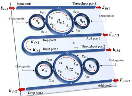
FromFig. 1, the electrical outputfield at the center ring is the electricalfield of the whispering gallery mode (EWGM), which is given in the cylindrical coordinates and found in the Refs.[12,13]. To sim-plify the equation, reflection from the reflector is neglected, whereas the reflection output is obtained as IWGMR=−RWGM IWGMR. RWGM. Here,RWGMis the reflectance of the applied material[14]. Finally, the simulation parameters were selected closer to the considered practical parameters[15]. The parameters used in simulations are given in the captions of relevantfigures. A selected light is fed into the system as the input electricfield (Ein). The electricfields are circulated within the system and described by the Eqs.(1) and (2) [16,17], the input electric field is fed into the z-axis, where Ein=EZ=E e0 −ik z ωt φz− + , E0is the initial electricfield amplitude, WhereE0is the electricfield amplitude
https://doi.org/10.1016/j.rinp.2018.08.052
Received 11 April 2018; Received in revised form 28 August 2018; Accepted 29 August 2018
⁎Corresponding author at: Computational Optics Research Group, Advanced Institute of Materials Science, Ton Duc Thang University, District 7, Ho Chi Minh City,
Viet Nam.
E-mail address:preecha.yupapin@tdtu.edu.vn(P. Yupapin).
Available online 05 September 2018
2211-3797/ © 2018 The Authors. Published by Elsevier B.V. This is an open access article under the CC BY license (http://creativecommons.org/licenses/BY/4.0/).
(real),kzis the wave number in the direction of propagation (z-axis),ω is the angular angular frequency, and is the initial phase.
The output intensity of the proposed single system is given by the transfer function of the output power (intensities) at through port and drop port given by Eqs.(1) and (2), respectively[17].
= −
− +
− −
E τ τ A
τ τ A E
κ κ A
τ τ A E
| | Φ
1 Φ
Φ
1 Φ
th2 2 1 in ad
1 2
1 2 1/2 1/2
1 2 2 (1) = − − + − −
E τ τ A
τ τ A E
κ κ A
τ τ A E
| | Φ
1 Φ
Φ
1 Φ
dr2 2 1 ad in
1 2
1 2 1/2 1/2
1 2
2
(2)
where A1/2=e(−αL/4) is the half-roundtrip amplitude (A =A1/22 ), Φ1/2=e(jωT/2) is the half-roundtrip phase contribution (Φ=Φ1/22 ), τ1/2=(1−κ1,22 )1/2,κ1andκ2are the coupling constants.
Before employing Eqs. (1) and (2) for simulations in MATLAB, preliminary results, as shown in Fig. 2, were obtained by using the graphical approach of the Optiwave program. Simulation of the laser input into thefirst system is illustrated inFig. 1. The center wavelength is 1.55 µm with a peak power of 10 mW. A fraction of this power is
coupled into the device that propagates throughout thefirst system and the output is obtained at the throughput port. Coupling constants and the other used parameters are given in the relatedfigure captions. Next, the output from the drop port is input into the second system and the processes repeat.
The output of the second system is also obtained at the throughput port. In application, the two-channel sensor mechanism can be formed by the Kerr-Vernier effect within the circuits, which isfirstly introduced by us in this work. InFig. 2, the plot shows graphical results obtained from the Optiwave program, where the input light wavelength center is at 1.55 µm,Rl1=Rr1=Rl2=Rr2= 1.2 µm,Rd1=Rd2= 2.0 µm, each of the coupling constant,κ1toκ8is 0.5, the refractive index;nChG= 2.9 [18],nSi= 3.47 (Si-Crystalline silicon).
The refractive index of Si is 3.47 The attenuation coefficient of the waveguide is 0.1 dB (mm)−1, Aeff= 0.50μm2. For simplicity, the wa-veguide loss is 0.5 for all wavelengths. The ChG dimension is given in the figure captions, the nonlinear refractive index n2= 10.20 × 10⁻¹⁸m2W−1 [20], linear refractive index n0= 2.90.
The fractional intensity lossγ= 0.1 and other parameters are given in the relatedfigure captions. The key parameter of such effects is the nonlinear refractive index (n2) of the ChG, which is the side ring (phase modulator) that induces the coupling of power into the centre ring (Si). This affects the output at the throughput and drop ports. Hence, the less input power from drop port is coupled into the second system and observed at the throughput and drop ports, A different amount of power is coupled into the two side rings (right and left rings of both system) that provides with different refractive index changes induced by the Kerr effect. The shift in wavelength (or frequency) between the throughput ports of the systems introduce different phase changes due to the refractive index changes and produce two-channel comparative results. In a similar manner, the Vernier effect of the two side rings is reported by Bahadoran et al.[1]. This is the on-chip scale circuit that can be used for two-channel measurements, where the shifts of the two comparative results can offer better measurement accuracy, in which self-calibration can be performed. Regarding Kerr effect, the change in the input power causes the change in the output of Kerr-Vernier effects output, which is a display of a two-channel sensor operation.
The Kerr-Vernier effects of the system can be seen by changing the input power into the system, from which the output signal of the second system will be shifted in phase (wavelength). In the microring system, which is ultimately reflected in the refractive index, given by the re-lationship as n =n0+n2I =n0+n P A2 / eff, where n0 and n2 are the linear and nonlinear refractive indexes, respectively. I is the optical intensity and P is the optical power.Aeff is the effective mode core area of the device. For the microring resonator, the effective mode core areas range from 0.1 to 0.5μm2[6]. The comparison of the results due to such effects is described in the following details.Fig. 3shows the simulations performed using MATLAB and the two-channel comparative results at (a) through ports, (b) the drop ports, (c) the WGM outputs. InFig. 4, the plot of the relationship between the input power and the changes in the output wavelengths with the two system outputs are compared, where the sensitivity of 1.2 Wm−1of the WGM output is obtained. In appli-cation, the initial measurement can be used as the off-set data before the sensing operation, therefore, if there is any change from the initial data will be the measurement values. Moreover, the shift in phase (optical path difference) from the two systems can be compared with each other, i.e. self-calibration. Moreover, the two-system can be used to form a sensor system in which one is the sensing unit and another one is performed the sensing unit, which has the potential of various sensor applications such as bio-sensors, mechanical sensors and other forms of sensor that requires the sensing and reference system com-parison (seeTable 1).
[image:3.595.50.279.56.223.2]To the best of our knowledge, this is thefirst time the concept of the double effects called the Kerr-Vernier effects is introduced by using the material device size and refractive indices. The concept is demonstrated by using the two coupling panda-ring resonators, where the nonlinear Fig. 1.A schematic of the on-chip Si-ChG microring circuits, whereRr,Rd,Rl
are the ring radii of the center ring and two side rings, right (Rr) and left (Rl)
hands, RSi: silicon ring radius.ESubs are the electrical fields in the related
[image:3.595.45.286.495.687.2]system.
Fig. 2.The grapical results of the wave propagation in the system inFig. 1
using the Optiwave program, where the input light source wavelength cenetr is at 1.55 µm, Rl1=Rr1=Rl2=Rr2= 1.2 µm, Rd1=Rd2= 2.0 µm, each of the
coupling constant,κ1toκ8is 0.5, the refractive index;nChG= 2.9,nSi= 3.47
(Si-Crystalline silicon).
J. Ali et al. Results in Physics 11 (2018) 144–147
material is the ChG. When light is input into the two systems, the Kerr effect is induced in both systems. By the difference in the propagation lengths, the longer length results in lower optical, which is observed by the phase differences. We have shown that the Kerr-Vernier effects within the microring resonator with the materials can be easily changed by applying the input power into the system, which is the external application. The comparison of the two outputs has shown that a phase shift of ∼120 µmW−1 is obtained with an applied input power was
fixed at 10 mW.
Acknowledgments
The authors would like to give the appreciation for the research
financial support and the research facilities andfinancial support from the Universiti Teknologi Malaysia, Johor Bahru, Malaysia through Flagship UTM shine project (03G82), Tier 1 (16H44) and Tier 2 (15J57) grants.
Appendix A. Supplementary material
Supplementary data associated with this article can be found, in the online version, athttps://doi.org/10.1016/j.rinp.2018.08.052.
References
[1] Sirawattananon C, Bahadoran M, Ali J, Mitatha S, Yupapin PP. Analytical Vernier effects of a Panda-ring resonator for microforce sensing application. IEEE Trans Nanotechnol 2012;11(4):707–12.
[2] Bahadoran M, Ali J, Yupapin PP. Ultrafast all-optical switching using signalflow graph for Panda resonator. Appl Opt 2013;52(12):2866–73.
[3] Bahadoran M, Ali J, Yupapin PP. Graphical approach for nonlinear optical switching by Panda Vernierfilter. IEEE Photon Technol Lett 2013;25(15):1470–3. [4] Sa-Ngiamsak W, Sirawattananon C, Srinuanjan K, Mitatha S, Yupapin PP.
Micro-optical gyroscope using a Panda-ring resonator. IEEE Sens J 2012;12(8):2609–13. [5] Chantanetra S, Teeka C, Mitatha S, Jomtarak R, Yupapin PP. Hybrid transistor
manipulation controlled by light within a Panda microring resonator. IEEE Trans NanoBiosci 2012;11(2):125–30.
[6] Phatharaworamet T, Teeka C, Jomtarak R, Mitatha S, Yupapin PP. Random binary code generation using dark-bright soliton conversion control within a panda ring resonator. J Lightwave Technol 2010;28(19):2804–9.
[7] Wu CL, Su SP, Lin GR. All-optical modulation based on silicon quantum dot doped SiOx:Si-QD waveguide. Laser Photon Rev 2014;8(5):766–76.
[8] Wu CL, Lin YH, Su SP, Huang BJ, Tsai CT, Wang HY, et al. Enhancing optical nonlinearity in a nonstoichiometric SiN waveguide for cross-wavelength all-optical data processing. ACS Photon 2015;2(8):1141–54.
[9] Wu CL, Chen BT, Lin YY, Tien WC, Lin GR, Chiu YJ, et al. Low-loss and high-Q Ta2O5based micro-ring resonator with inverse taper structure. Opt Express
2015;23(20):26268–75.
[10] Su SP, Wu CL, Cheng CH, Huang BJ, Wang HY, Tsai CT, et al. Nonstoichiometric SiC bus/ring waveguide based all-optical data format follower and inverter. ACS Photon 2016;3(5):806–18.
[11] Saktioto T, Irawan I, Yupapin P, Phatharacorn P. A single eye 3D image perception device using vertical double ring resonator construction. Microwave Opt Technol Lett 2015;57(8):1802–5.
[image:4.595.45.284.55.548.2][12] Phatharacorn P, Chiangga S, Yupapin P. Analytical and simulation results of a triple Fig. 3.Plot of the simulation results of the used parameters inFig. 2using the
[image:4.595.312.553.56.185.2]MATLAB program, where comparative results of the two-channel outputs at the (a) through ports, (b) the drop ports, (c) the WGM outputs. The through port signals present the Kerr-Vernier transmission outputs of the system.
Fig. 4.The free spectrum range (FSR) of the output peak signals of the different input light sources from 1.0 to 2.0 µm. The plot (Δ /λ λ) has shown the trend of linearity. The comparative results from (a) Th1 and Th2 in blue, (b) Dr1 and Dr2 in red, and (c) WGM1 and WGM2 in black, the data points and the solid lines are the simulation and the curvefitting point, respectively.
Table 1
Relative parameters of the Si-ChG microring system.
Rl1,Rl2 Rr1,Rr2 Rd1,Rd2 Waveguide κ1-κ8
Radius [µm] 1.2 1.2 2.0 – –
Aeff[µm2] 0.25 0.25 0.25 0.25 –
nSi – – 3.47 3.47 –
n0 2.9 2.9 – – –
nChG [m2 W−1] 10.2 × 10⁻¹⁸ 10.2 × 10⁻¹⁸ – – –
Q[19] ∼603 ∼603 ∼103 – –
[image:4.595.308.558.277.361.2]micro whispering gallery mode probe system for a 3D bloodflow rate sensor. Appl Opt 2016;55(33):9504–13.
[13] Ali J, Youplao P, Pornsuwancharoen N, Aziz MS, Chiangga S, Amiri IS, et al. On-chip remote charger model using plasmonic island circuit’. Results Phys 2018;9:815–8.
[14] Chaiwong K, Tamee K, Punthawanunt S, Suhailin FH, Aziz MS, Ali J, et al. Naked-eye 3D imaging model using the embedded micro conjugate mirrors within the medical micro-needle device. Microsyst Technol 2018;24(6):2695–9.
[15] Wang W, Chu ST, Little BE, Pasquazi A, Wang Y, Wang L, et al. Dual-pump Kerr micro-cavity optical frequency comb with varying FSR spacing. Sci Rep 2016;6:28501.
[16] Soysouvanh S, Jalil MA, Amiri IS, et al. Ultra-fast electro-optic switching control
using a soliton pulse within a modified add-drop multiplexer. Microsyst Technol 2018;24(9):3777–37782.
[17] Amiri IS, Ali J, Yupapin PP. Enhancement of FSR andfinesse using add-dropfilter and panda ring resonator system. Int J Mod Phys 2012;B 26:1250034. [18] Zakery A, Elliott SR. Optical nonlinearities in chalcogenide glasses and their
ap-plications, IX; 2007. 202 p., ISBN: 978-3-540-71066-0.
[19] Bogaerts W, Heyn PD, Vaerenbergh TV, Vos KD, Selvaraja SK, Claes T, et al. Silicon microring resonators. Laser Photon Rev 2012;6(1):47–73.
[20] Smektala F, Quemard C, Leneindre L, Lucas J, Barthélémy A, De Angelis C. Chalcogenide glasses with large non-linear refractive indices. J Non-Cryst Solids 1998;239(1–3):139–42.
J. Ali et al. Results in Physics 11 (2018) 144–147