Abstract—Acoustic metamaterials have recently become of interest for their ability to attenuate sound by breaking the mass-density law. In this paper, acoustic metamaterials based on Helmholtz resonators and capable of attenuating sound up to 30 dB are fabricated for sound absorption applications in the small-scale. The proposed metamaterials are subwavelength at a factor of 𝝀/𝟏𝟐 with respect to the lateral dimension of the units. The directional response due to the position of the acoustic source on the sound attenuation provided by the metamaterial is investigated by controlling the location of a loudspeaker with a robot arm. To enhance and broaden the absorption bands, structural modifications are added such that overtones are tuned to selected frequencies, and membranes are included at the base of the resonators. This design is made possible by innovative 3D printing techniques based on stereolithography and on the use of specific UV-curable resins. These results show that these designs could be used for sound control in small-scale electroacoustic devices and sensors.
Index Terms—Acoustic Metamaterials – Helmholtz Resonators – Overtones – Membranes – Sound Absorption – Stop Bands – 3D Printing
INTRODUCTION
he attenuation of sound in small-scale devices is not a trivial endeavour, since acoustic waves can easily penetrate thin walls. According to the mass-density law, the transmission of sound T is proportional to the inverse of density 𝜌, thickness 𝑑 of the material and to the angular frequency 𝜔 of the sound wave [1], [2]:
𝑇 ∝ (𝜌𝜔𝑑)-. . (1)
Therefore, to halve the sound transmission of a material, i.e. to decrease it by 6 dB, it is necessary to double its thickness, density or the acoustic frequency. In recent years, acoustic
Manuscript submitted April 17, 2018. This research is funded by the European Research Council under the European Union’s Seventh Framework Programme (FP/2007-2013) / ERC Grant Agreement n. [615030].
Cecilia Casarini, Ben Tiller, Carmelo Mineo, Charles N. MacLeod, James F. C. Windmill and Joseph C. Jackson are members of the Centre for Ultrasonic Engineering, Electronic and Electrical Engineering Department, University of Strathclyde, Glasgow, Scotland, UK. e-mail: cecilia.casarini@strath.ac.uk. An earlier version of this paper was presented at the IEEE Sensors Conference 2017 in Glasgow (UK) and was published in its Proceedings (IEEEXplore URL: https://ieeexplore.ieee.org/abstract/document/8234381/).
metamaterials have been studied because of their ability to control sound waves in unusual ways, thanks to their properties such as negative effective density and bulk modulus [3], [4]. When these parameters are negative, stop bands are formed where the sound at specific frequencies is deeply attenuated. Acoustic metamaterials can break the mass-density law by exploiting the stop bands formed in the proximity of the resonance frequencies of their unit cells.
These material structures are often based on Helmholtz resonators [5], [6], [7], [8] and membranes [9], [10], [11], [12], [13]. The frequency band that is attenuated by using these kind of unit cells is nevertheless narrow, hence solutions such as coupling of multiple resonances and leveraging the losses of the materials are generally used to make the attenuation broadband [14], [15], [16], [17], [18] .
In this paper, we present subwavelength small-scale 3D printed acoustic metamaterials based on Helmholtz resonators capable of generating stop bands where the sound is attenuated. In Section II a basic design of the metamaterials is presented, where Helmholtz resonators arrays are shown to generate stop bands where sound attenuation increases with the number of unit cells. By using a robot arm [19] guiding a loudspeaker through a quarter-hemisphere trajectory, we show in Section III that an absorption band is formed for every angle of incidence of the impinging sound wave. In order to obtain a broadband sound attenuation, we then present two ways to enhance the stop band in Section IV and V. Firstly, the overtones of the resonators are tuned to be closer to the fundamental frequency and thus the stop band becomes wider. Secondly, membranes are printed at the base of the resonators to obtain a similar broadband attenuation.
In recent years acoustic metamaterials have seen advancement in sound focusing and waveguiding, acoustic cloaking, imaging and computation [20], [21], [22], [23], [24], [25]. However, the results often still remain confined in a laboratory environment and have not been fully integrated into functional devices. In this work a novel fabrication technique is used, where thin membranes are fabricated inside Helmholtz resonators, the two units consisting of different materials. The presented manufacturing technique could result in rapid prototyping of metamaterials and contribute to the advancement of this field into the industrial environment. Simple physical models of the presented metamaterials are included in each section, nevertheless this work is mostly based on experimental results and aims at developing
Enhancing the Sound Absorption of Small-Scale
3D Printed Acoustic Metamaterials Based on
Helmholtz Resonators
Cecilia Casarini, Student Member, IEEE, Ben Tiller, Carmelo Mineo, Charles N. MacLeod, James F. C. Windmill, SeniorMember, IEEE and Joseph C. Jackson
metamaterials that could be included in real devices. Potential applications of this work include noise cancellation for devices such as headphones, hearing aids and other sensors [26], [27].
SMALL-SCALE HELMHOLTZ RESONATORS
A. Sample Design and Fabrication
In previous studies soda cans were successfully used as acoustic metamaterials to generate stop band and attenuate sound [6]. Therefore, we designed the unit cell of the acoustic metamaterial as a Helmholtz resonator having the dimensions of a soda can scaled down by a factor of 20. The neck of the resonator has an inner radius of 0.564 mm and a length of 0.5 mm, the cavity has an inner radius of 1.6 mm and a length of 5.8 mm. The thickness of the walls is 0.5 mm. The fundamental frequency of each resonator is at 6.8 kHz and is given by:
where 𝑐 is the speed of sound in the air, 𝑆 is the cross-sectional area of the neck, 𝑎 is the radius of the neck, 𝑙 is the length of the neck, 𝐿5= 𝑙 + 1.7𝑎 is the extended length of the neck, and 𝑉 is the volume of the cavity [28].
The Asiga (Sydney, Australia) Freeform Pico Plus 3D printer used to fabricate the metamaterials described in this paper is based on an upside-down stereolithography system. The X-Y plane pixel resolution is 27 µm and the Z-axis scale can be set in 1 µm increments. To obtain the material to fabricate the resonators we mixed the clear resin (Formlabs, Somerville, Massachusetts, U.S.) with 0.15% of Sudan I (SI) and 1% of Irgacure 819 (Sigma-Aldrich, St. Luis, Missouri, U.S.). The clear resin was chosen as monomer for its large Young’s Modulus that allowed us to consider the walls of the resonators as rigid structures that do not influence their resonances. Autodesk Inventor 2018 was used to design the CAD model of the resonators.
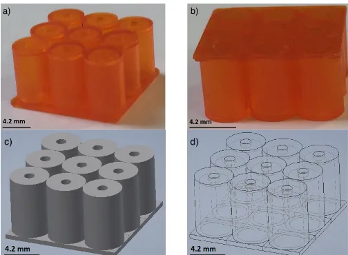
Fig. 1 Front view (a) and bottom view (b) of the small-scale acoustic metamaterials based on a 3´3 array of Helmholtz resonators. Equivalent CAD model (c) and wireframe view (d).
B. Measurements and Results
A periodic chirp between 100 Hz and 20 kHz was generated by a function generator (Keysight Technologies, Santa Rosa CA, U.S.) and emitted by a 8 Ω, 2″ loudspeaker (Visaton, Haan, Germany). A Bruel & Kjaer (B&K, Nærum, Denmark) 1/8” pressure-field microphone connected to a pre-amplifier (B&K Nexus Microphone Conditioner) and positioned above the metamaterials, transmitted the acquired signal to a laptop running a MATLAB session-based interface via a National Instruments (Austin, Texas, U.S.) data acquisition system. We tested metamaterials composed of 3´3, 3´6 and 6´6 arrays of the unit cells. A reference signal was gathered without the samples and a measurement was taken above each unit. The two signals, in dB, were then subtracted to obtain the normalized sound transmission.
As shown in Figure 2, above the resonance frequency, 5.9% lower than one analytically predicted, a stop band is generated where the sound is attenuated. The sound transmission was measured above a 3´3, 3´6 and 6´6 array of resonators and was found that by increasing the number of resonators, the stop band becomes deeper and the incoming sound wave is attenuated approximately 10 dB, 20 dB and 30 dB respectively (Fig. 2).
These stop bands are a byproduct of interferences: when the frequency of the sound wave driving the metamaterial corresponds to one of its resonances, the mass of air in the neck of the resonator oscillates at a high amplitude and at the same time a change in phase occurs. At a frequency right above the resonance, the mass of air still presents a high oscillation amplitude, but in antiphase with the impinging wave, resulting in destructive interference between the incoming sound and the acoustic wave generated by the resonator. Therefore, the sound is attenuated without doubling the thickness of the material, its density or the frequency of interest, hence the metamaterials are capable of breaking the mass-density law [6].
If we consider a Helmholtz resonator as a simple harmonic oscillator, it can be described by the equation of motion of the driven damped harmonic oscillator [29]:
𝑥̈ + 𝛾𝑥̇ + 𝜔?@𝑥 = 𝐹(𝑡), (3)
where 𝛾 represents damping, 𝜔? is the fundamental angular resonance frequency of the system and 𝐹(𝑡) is the driving force per unit mass (i.e. driving acceleration). To illustrate the phenomenon, we consider the driven harmonic oscillator (Eq. 3) in which the response of 𝑁 Helmholtz resonators is added to the input forcing, such that we can describe a variable
𝑦(𝑡) = 𝐹(𝑡)/𝜔?@+ α𝑁𝑥(𝑡) where 𝑁 is the number of Helmholtz resonators and 𝛼 is a the ratio of pressure from the field generated by the Helmholtz resonators and the external field, chosen arbitrarily to match experimental data. The variable 𝑦(𝑡) represents the sum of the external driving force and the motion of the oscillator, which can be considered to be analogous to the acoustic pressure summed from both an external field and the pressure output from a driven Helmholtz resonator. Assuming that the external drive is sinusoidal, i.e.
𝑓?=
𝑐 2𝜋K
𝑆
[image:2.612.47.299.512.697.2]𝐹(𝑡) = 𝐹𝑒MNO, we can solve for 𝑦(𝑡) in the complex domain such that the spectral response of 𝑦(𝑡) is given by:
𝑌(𝜔) = 𝐹
𝜔?@
K𝛾@𝜔@+ (𝜔@− (1 + 𝛼𝑁)𝜔?@)@
𝛾@𝜔@+ (𝜔@− 𝜔
?@)@ .
(4)
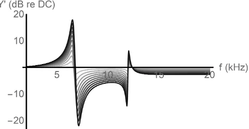
Figure 3 shows the existence of the stop band just beyond the resonance of the Helmholtz resonator(s), chosen to be 6.6kHz. Given that the lateral distance between the centers of the units is 4.2 mm, the metamaterials are subwavelength at a factor of
𝜆/12. Data in this graph is normalized to the Helmholtz resonator response at 0 Hz and scaled to match real measured values. Clearly the effect of the resonator is to attenuate sharply the response immediately after the resonance frequency. There is a concomitant increase in response before resonance, and an asymmetry in the relative gain or attenuation below or above resonance. This model therefore explains simply how a Helmholtz resonator can be used to generate a stop band.
Fig. 2 Graph of normalized sound transmission as a function of frequency, showing an increase in sound attenuation with higher number of resonators. It can be noticed that the band gap is detuned with increased number of resonators. This could be due to some imperfections in the fabrication process and this problem will be addressed in future designs of the metamaterials.
Fig. 3 Plot of the sum of the response of N oscillators and an external sinusoidal driving force. The values of 𝛼 (1%) and 𝛾 (2500) have been
scaled to correlate with experimentally determined responses. Each curve represents the range of N from 1 to 10, with 10 being the darkest.
MAPPING THE STOP BAND
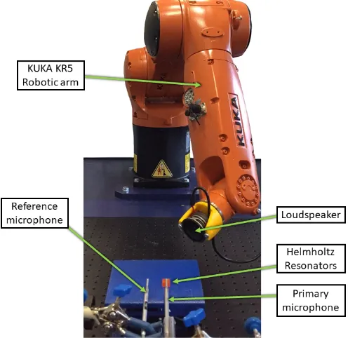
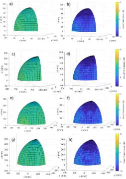
A study on the effects of the position of the source with respect to the stop band was conducted by utilizing an industrial six Degree of Freedom (D.O.F.) robot [30]. This approach allowed for controlled and repeatable scanning not only of traditional 3 DOF (x, y, z) positions but also in roll, pitch and yaw orientations (Fig. 4). The robot arm was programmed to trace a quarter hemisphere around the sample, at a distance of 100, 200, 300 and 400 mm. A loudspeaker was mounted on the robot arm, and the execution of the robot path was controlled by custom MATLAB code interfaced with the robot controller through the KUKA Robot Sensor Interface (RSI) [31]. The data acquisition was synchronized with the progression of the robot path. Thus, the collected data was encoded with the robot positional feedback, received through RSI. Two calibrated microphones measured the response above the sample and outside its nearfield as a reference. As shown in Fig. 5, the sound is attenuated in the stop band (i.e. at 6600 Hz) for each source position, with an increasing attenuation when the loudspeaker is above the sample, i.e. facing the front of the aperture of the neck of the resonators. The effect of sound attenuation is present for measurement spheres of different radiuses, namely 100, 200, 300 and 400 mm and it is consistent for all the chosen distances.
[image:3.612.57.294.310.494.2] [image:3.612.316.564.387.628.2] [image:3.612.47.299.571.703.2]Fig. 5 Sound transmission of the sample at 5000 Hz (left) and 6600 Hz (right)
with respect to the source position along a quarter hemisphere with a radius of 100, 200, 300 and 400 mm.
ENHANCING THE STOP BAND WITH TUNED OVERTONES
The first method to enhance the stop band was to modify the dimensions of the resonators in order to tune the overtones to a frequency closer to the fundamental. In fact, while the resonance frequency of Helmholtz resonators is the result of oscillation of air in the neck, acting as an inertial ‘mass’, and in the cavity, which functions as a mechanical spring, the overtones are a result of standing waves in the cavity alone. Their frequencies can be approximated to the resonances of a pipe open at both ends when the volume is large, and to the ones of the pipe closed at one end for smaller volumes [29]. In the first case, the overtones are given by:
𝑓V= (𝑛 − 1)
𝑐
2ℎ′ . (5)
(n = 2, 3, 4, ...) In the second case, the overtones are given by:
𝑓V= (2𝑛 − 1)
𝑐
4ℎ′ , (6)
(n = 1, 2, 3, …) where 𝑐 is the speed of sound in air, ℎ5= ℎ + 0.6𝑟 is the effective length of the cavity and r is its radius. We fabricated acoustic metamaterials based on Helmholtz resonators having a neck radius of 1 mm and a length of 0.5 mm, and a cavity with a radius of 1.6 mm and a length of 10.8 mm. As
[image:4.612.323.562.157.543.2]expected, the fundamental frequency and the first overtone in this metamaterials structure were closer than in the one with the dimensions of a soda can scaled down by a factor of 20. In the latter case, the two stop bands were narrow, 15 dB and 20 dB deep and separated by a frequency band 6.5 kHz wide where the sound was not attenuated. In the case of metamaterials with tuned overtones, the two stop bands were 2.5 kHz apart, 20 dB and 25 dB deep and separated by a frequency band where the sound was still attenuated by 10 dB (See Fig. 6).
Fig. 6 Narrow stop bands 6.5 kHz apart, originated in acoustic metamaterials with unit cells having the dimensions of a soda can scaled down by a factor of 20 (a). Closer stop bands 2.5 kHz apart and joined by an absorption band where the sound is still attenuated by 10 dB, generated by acoustic metamaterials with tuned overtones (b).
ENHANCING THE STOP BAND WITH MEMBRANES
The second method to enhance the stop band of the acoustic metamaterials consisted of 3D printing a thin membrane instead of a rigid wall at the base of each Helmholtz resonator. Following the method in section II, we again consider a simple harmonic oscillator driven by an external sound field, representing a forced Helmholtz resonator. With a membrane however, there is a second oscillator, with pressure z(t), driven by the pressure of the Helmholtz resonator, such that the sound field near the resonator can be given by 𝑦′(𝑡) =](O)N
^
α𝑁𝑥(𝑡) + 𝜔?@α𝑁𝑧(𝑡), which is the sum of the external field, the resonator pressure, and the membrane contribution to pressure. This system was solved with Mathematica (Champaign, Illinois, US), and while the solution is analytic, it is complicated and not presented here. However, Figure 7 shows the additional effect of a membrane, if the membrane’s resonance was 12kHz.
Fig. 7 Graph showing the frequency response of an array of Helmholtz resonators with membranes. The parameters are the same as in Figure 3. Note that the addition of membranes deepens and widens the stop band.
This simple model serves as an illustration of the potential for a membrane to widen the band gap if its resonant frequency was chosen appropriately.
Before fabricating this structure, a process of trial and error to print just the membranes was first developed. We tested three different monomers, namely the Formlabs clear resin, polyethylene glycol diacrylate (PEGDA) and bisphenol A ethoxylate dimethacrylate (BEMA) each of them having different parameters, as reported in Table 1. PEGDA and BEMA were purchased from Sigma-Aldrich, St. Luis, Missouri, U.S. Each of these monomers was mixed with the photoinitiator Irgacure 819 (1%) and with different amounts of the absorber Sudan I. During the 3D printing process, the CAD model is split by the printer software into several layers with a chosen thickness. The light injected into the build tray containing the fluid polymerizes it according to the CAD model, and each layer is formed. When part of a layer is not standing above a previous one (i.e. is printed on a void), a membrane can be formed of a thickness dependent on the chosen exposure time and on the amount of Sudan I in the fluid [32]. Different amounts of Sudan I were added to the main monomers to obtain the most suitable results for exposure times between 1 s and 5 s. The three finalized fluids were respectively clear resin with 0.15% Sudan I, PEGDA with 0.2% Sudan I and BEMA with 0.125% Sudan I. It is important to note that the amount of absorber material can be changed in order to match the exposure times between different resins and hence print objects formed of multiple fluids. In this case we chose the amount of Sudan I to be added to the BEMA to match the optimal exposure time of PEGDA, to be able to print a metamaterial based on PEGDA with BEMA membranes. We then printed the membranes of the three resins with various exposure times to achieve different thicknesses. Figure 8 represents the thickness of the three membranes in relation to the exposure time. Different thicknesses can be obtained by varying the exposure time or the amount of absorber in the fluids.
For this design the resonators were made of PEGDA and the wall thickness was 1 mm, to overcome the lower Young’s Modulus of PEGDA in comparison to the clear resin and hence to consider the walls as rigid. The membrane's resonance frequency 𝑓? for the 01 mode is given by [33]:
𝑓? =
0.4694𝑑
𝑟@ K
𝐸
𝜌(1 − ν@) , (7)
where 𝑑 is the thickness of the membrane, 𝑟 is its radius, 𝐸 is the Young’s modulus of the material, 𝜌 is the density and ν is the Poisson’s ratio. After 3D printing the metamaterials described above with the three fluids, we observed a stress was added in the manufacturing process that in this case resulted in a fundamental frequency augmented by a factor of 2.5. At present this stress is unquantifiable. The metamaterials made of PEGDA with membranes in BEMA gave us the best results in terms of manufacturing and acoustic properties. Therefore, we present results for metamaterials made of PEGDA Helmholtz resonators with a membrane in BEMA on the bottom, having a thickness of 170 µm.
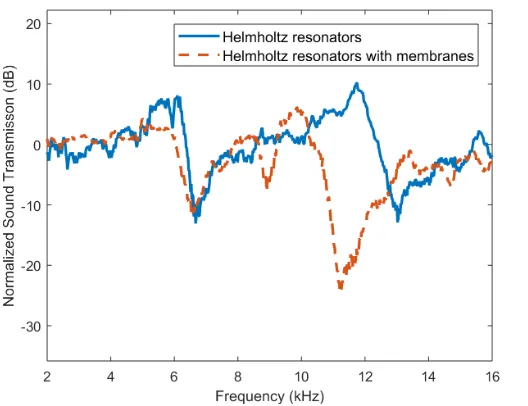
[image:5.612.311.573.73.133.2]We first measured the sound transmission in metamaterials composed of simple Helmholtz resonators made with PEGDA. As shown in Figure 10, the resonances of the membranes widened the stop bands produced by the resonators alone: a stop band at 9 kHz that was not present in the first sample is visible and the stop band of the first overtone is shifted onto a 2 kHz lower band and enhanced by 10 dB.
Fig. 8 Thickness of the membranes against exposure time of UV light during the 3D printing process. Longer exposure times will result in thicker membranes. The relation between these two parameters varies with the material used and the amount of absorber in the fluid.
TABLEI MATERIAL PROPERTIES
Symbol Quantity Clear PEGDA BEMA
𝐸 Young’s Modulus (Pa) 2.8´109 250´106 12.8´106
𝜌 Density (Kg/m3) 1180 1180 1099
ν Poisson’s Ratio 0.33 0.35 0.4
[image:5.612.50.300.133.263.2]Fig. 9 Front view (a) and bottom view (b) of acoustic metamaterials based on membranes and Helmholtz resonators. Equivalent CAD model with cut away section (c) and bottom view (d). The membranes have been highlighted in yellow for a better understanding of the design.
Fig. 10 Sound transmission of the acoustic metamaterials based Helmholtz resonators (blue) and based on Helmholtz resonators with membranes (red). The signal has been acquired above the resonator in the middle of a 3´3 array.
CONCLUSIONS AND FURTHER WORK
We successfully 3D printed small-scale acoustic metamaterials capable of breaking the mass-density law and of deeply attenuating sound in specific frequency bands. We also showed that, for every source position along a quarter hemisphere, the sound above the metamaterials is attenuated in the generated stop bands. However, when the source is situated above the aperture of the neck, the sound attenuation becomes higher. In order to absorb sound in broader and deeper frequency bands we tuned the overtones of the Helmholtz resonators and moved them closer to the fundamental frequency. A similar effect was also obtained by 3D printing membranes at the base of the resonators.
Additive manufacturing technology based on stereolithography was confirmed to be a reliable and
promising way to manufacture acoustic metamaterials, since it allowed us to choose the resonators parameters that were most convenient for our purposes. Through this manufacturing technique, it was also possible to use different materials to fabricate membranes and resonators in the same build. Future work will exploit the capabilities of 3D printing to fabricate acoustic metamaterials based on different shapes and containing more resonances.
This type of acoustic metamaterials for sound control could be integrated in electroacoustic devices such as headphones and hearing aids. For example, to eliminate feedback in electroacoustic devices containing both a microphone and a loudspeaker porous materials such as foam and gel are often used. Metamaterials could be preferable in certain applications where the corruption of foam over time or the movement of gel to neighboring locations could be difficult to contain. Moreover, metamaterials could be used to attenuate a specific frequency band instead of the full spectrum as in traditional absorbers. In-ear headphones could be 3D printed with a shape corresponding to the listener external ear and designed according to the proposed metamaterials. This light-weight design could be preferable to sealed in-ear headphones as they would not have to be inserted in the ear-canal. Further work will consist in prototyping the ideas above and test them both experimentally and through user studies.
ACKNOWLEDGMENT
The authors would like to thank the researchers within the Centre for Ultrasonic Engineering at Strathclyde University for their support during this work.
REFERENCES
[1] P. Sheng, X. X. Zhang, Z. Liu, and C. T. Chan, “Locally resonant sonic materials,” in Physica B: Condensed Matter, 2003.
[2] Z. Yang, H. M. Dai, N. H. Chan, G. C. Ma, and P. Sheng, “Acoustic metamaterial panels for sound attenuation in the 50–1000 Hz regime,” Appl. Phys. Lett., vol. 96, no. 4, p. 41906, 2010. [3] G. Ma and P. Sheng, “Acoustic metamaterials: From local
resonances to broad horizons,” Sci. Adv., vol. 2, no. 2, pp. e1501595–e1501595, 2016.
[4] S. A. Cummer, J. Christensen, and A. Alù, “Controlling sound with acoustic metamaterials,” Nat. Rev. Mater., vol. 1, no. 3, p. 16001, 2016.
[5] N. Fang et al., “Ultrasonic metamaterials with negative modulus,”
Nat. Mater., vol. 5, no. 6, pp. 452–456, 2006.
[6] F. Lemoult, N. Kaina, M. Fink, and G. Lerosey, “Wave propagation control at the deep subwavelength scale in metamaterials,” Nat Phys, vol. 9, no. 1, pp. 55–60, Jan. 2013.
[7] N. Jiménez, T. J. Cox, V. Romero-García, and J.-P. Groby, “Metadiffusers: Deep-subwavelength sound diffusers,” Sci. Rep., vol. 7, no. 1, p. 5389, 2017.
[8] S. Zhang, L. Yin, and N. Fang, “Focusing Ultrasound with an Acoustic Metamaterial Network,” Phys. Rev. Lett., vol. 102, no. 19, p. 194301, May 2009.
[9] Z. Yang, J. Mei, M. Yang, N. H. Chan, and P. Sheng, “Membrane-type acoustic metamaterial with negative dynamic mass,” Phys. Rev. Lett., 2008.
[10] T.-Y. Huang, C. Shen, and Y. Jing, “Membrane- and plate-type acoustic metamaterials,” J. Acoust. Soc. Am., vol. 139, no. 6, pp. 3240–3250, 2016.
[11] F. Bongard, H. Lissek, and J. R. Mosig, “Acoustic transmission line metamaterial with negative/zero/positive refractive index,” Phys. Rev. B, vol. 82, no. 9, p. 94306, Sep. 2010.
[image:6.612.48.312.311.514.2]sound,” Nat. Commun., 2012.
[13] B. I. Popa and S. A. Cummer, “Non-reciprocal and highly nonlinear active acoustic metamaterials,” Nat. Commun., 2014.
[14] J. Fey and W. M. Robertson, “Compact acoustic bandgap material based on a subwavelength collection of detuned Helmholtz resonators,” J. Appl. Phys., vol. 109, no. 11, p. 114903, Jun. 2011. [15] C. Casarini, J. F. C. Windmill, and J. C. Jackson, “3D printed
small-scale acoustic metamaterials based on Helmholtz resonators with tuned overtones,” in IEEE Sensors Conference, 2017.
[16] V. Romero-Garciá, G. Theocharis, O. Richoux, A. Merkel, V. Tournat, and V. Pagneux, “Perfect and broadband acoustic absorption by critically coupled sub-wavelength resonators,” Sci. Rep., 2016.
[17] Y. Tang et al., “Hybrid acoustic metamaterial as super absorber for broadband low-frequency sound,” Sci. Rep., 2017.
[18] X. Fang, J. Wen, B. Bonello, J. Yin, and D. Yu, “Ultra-low and ultra-broad-band nonlinear acoustic metamaterials,” Nat. Commun., 2017.
[19] B. D. Chivers et al., “Distribution of sound pressure around a singing cricket: radiation pattern and asymmetry in the sound field,”
Bioacoustics, vol. 25, no. 2, pp. 161–176, May 2016.
[20] S. Guenneau, A. Movchan, G. Pétursson, and S. A. Ramakrishna, “Acoustic metamaterials for sound focusing and confinement,” New J. Phys., 2007.
[21] S. H. Lee and O. B. Wright, “Origin of negative density and modulus in acoustic metamaterials,” Phys. Rev. B, vol. 93, 2016. [22] F. Zangeneh-Nejad and R. Fleury, “Acoustic Analogues of
High-Index Optical Waveguide Devices,” Feb. 2018.
[23] H. Chen and C. T. Chan, “Acoustic cloaking in three dimensions using acoustic metamaterials,” Appl. Phys. Lett., 2007. [24] F. Zangeneh-Nejad and R. Fleury, “Performing Mathematical
Operations using High-Index Acoustic Metamaterials,” Mar. 2018. [25] J. Zhu et al., “A holey-structured metamaterial for acoustic
deep-subwavelength imaging,” Nat. Phys., 2011.
[26] H. Esfahlani, S. Karkar, H. Lissek, and J. R. Mosig, “Exploiting the leaky-wave properties of transmission-line metamaterials for single-microphone direction finding,” J. Acoust. Soc. Am., vol. 139, no. 6, pp. 3259–3266, 2016.
[27] Y. Xie, T.-H. Tsai, A. Konneker, B.-I. Popa, D. J. Brady, and S. A. Cummer, “Single-sensor multispeaker listening with acoustic metamaterials,” Proc. Natl. Acad. Sci. , vol. 112, no. 34, pp. 10595– 10598, Aug. 2015.
[28] L. E. Kinsler, A. R. Frey, A. B. Coppens, and V. Sanders, James,
Fundamentals of acoustics. Wiley, 2000.
[29] N. H. (Neville H. Fletcher, Acoustic systems in biology. Oxford University Press, 1992.
[30] C. N. MacLeod, R. Summan, G. Dobie, and S. G. Pierce, “Quantifying and Improving Laser Range Data When Scanning Industrial Materials,” IEEE Sens. J., vol. 16, no. 22, pp. 7999–8009, 2016.
[31] C. Mineo, S. G. Pierce, P. I. Nicholson, and I. Cooper, “Robotic path planning for non-destructive testing – A custom MATLAB toolbox approach,” Robot. Comput. Integr. Manuf., vol. 37, pp. 1– 12, 2016.
[32] H. Gong, M. Beauchamp, S. Perry, A. T. Woolley, and G. P. Nordin, “Optical Approach to Resin Formulation for 3D Printed Microfluidics.,” RSC Adv., vol. 5, no. 129, pp. 106621–106632, Dec. 2015.
[33] P. M. C. Morse, Vibration and Sound. McGraw-Hill Book Company, 1948.
Cecilia Casarini (S’17) is a PhD
student in Electronic & Electrical Engineering within the Centre for Ultrasonic Engineering at the University of Strathclyde in Glasgow, UK. Her research focuses on 3D printed acoustic metamaterials for applications to noise and sound control for electroacoustic devices and sensors. In 2018 she was intern in the Acoustics Hardware team at Apple, Inc. in Cupertino, CA.
She received a MSc degree in Acoustics and Music Technology in 2016 at the University of Edinburgh, UK.
Benjamin Tiller is a Postdoctoral
researcher in the Department of Electronic and Electrical Engineering at the University of Strathclyde, Glasgow, United Kingdom. He graduated from the University of Nottingham with an MSci degree in Physics and then received his PhD degree in Biomedical Engineering from University of Glasgow In 2016. His PhD research focused on the Physics of acoustic streaming in microfluidic channels, and phononic sensors. His current research interests focus on 3D printing of functional materials and novel acoustic sensors.
Carmelo Mineo is a Research Fellow
in the Centre for Ultrasonic Engineering (CUE) of the department of Electrical and Electronic Engineering at the University of Strathclyde. With a background in mechanical engineering and laser ultrasound, he joined CUE in 2012 to undertake a PhD in Automated Non-Destructive Inspection of Large and Complex Geometries of Composite Materials. His current research interests comprise all aspects of the operation of robotic cells, including programming, instrument interfacing and data collection. Carmelo has vast experience in industrial engineering areas such as robotics, sensors, mechanical design, software, system integration, interfacing and control.
Charles MacLeod is a Lecturer in the
Centre for Ultrasonic Engineering. After being awarded a Masters in Electrical and Mechanical Engineering with Distinction at Strathclyde, Charles then went on to undertake a PhD in Automated Non – Destructive Evaluation. While undertaking his PhD Charles, was seconded to Spirit AeroSystems, in Prestwick to undertake Knowledge Exchange activities built on fundamental EPSRC funded research. Charles was awarded the prestigious University of Strathclyde EPSRC Doctoral Prize for 2014, for his work investigating automated NDE. Charles has vast experience in electrical and mechanical engineering areas such as robotics, sensors, electronics, mechanical fixturing and software.
James F. C. Windmill (M’99-SM’17)
acoustic systems, from the fundamental biology to various engineering application topics.
Joseph C. Jackson is a Lecturer in