This is a repository copy of Synthesis and characterisation of the hollandite solid solution Ba1.2-xCsxFe2.4-xTi5.6+xO16 for partitioning and conditioning of radiocaesium .
White Rose Research Online URL for this paper: http://eprints.whiterose.ac.uk/128864/
Version: Accepted Version
Article:
Bailey, D.J., Stennett, M.C., Mason, A.R. et al. (1 more author) (2018) Synthesis and characterisation of the hollandite solid solution Ba1.2-xCsxFe2.4-xTi5.6+xO16 for partitioning and conditioning of radiocaesium. Journal of Nuclear Materials, 503. pp. 164-170. ISSN 0022-3115
https://doi.org/10.1016/j.jnucmat.2018.03.005
[email protected] https://eprints.whiterose.ac.uk/
Reuse
Items deposited in White Rose Research Online are protected by copyright, with all rights reserved unless indicated otherwise. They may be downloaded and/or printed for private study, or other acts as permitted by national copyright laws. The publisher or other rights holders may allow further reproduction and re-use of the full text version. This is indicated by the licence information on the White Rose Research Online record for the item.
Takedown
If you consider content in White Rose Research Online to be in breach of UK law, please notify us by
Synthesis and characterisation of the hollandite solid solution
Ba
1.2-xCs
xFe
2.4-xTi
5.6+xO
16for partitioning and conditioning of radiocaesium
Daniel J. Bailey1, Martin C. Stennett1, Amber R. Mason1 and Neil C. Hyatt1
1- Immobilisation Science Laboratory, Department of Materials Science and Engineering, University of Sheffield, United Kingdom
Abstract
The geological disposal of high level radioactive waste requires careful budgeting of the heat load produced by radiogenic decay. Removal of high-heat generating radionuclides, such as
137Cs, reduces the heat load in the repository allowing the remaining high level waste to be
packed closer together therefore reducing demand for repository space and the cost of the disposal of the remaining wastes. Hollandites have been proposed as a possible host matrix for the long-term disposal of Cs separated from HLW raffinate. The incorporation of Cs into the hollandite phase is aided by substitution of cations on the B-site of the hollandite structure, including iron. A range of Cs containing iron hollandites were synthesised via an alkoxide-nitrate route and the structural environment of Fe in the resultant material characterised by Mössbauer and X-ray Absorption Near Edge Spectroscopy. The results of spectroscopic analysis found that Fe was present as octahedrally co-ordinated Fe (III) in all cases and acts as an effective charge compensator over a wide solid solution range.
1. Introduction
To improve the thermal budgeting of a future geological disposal facility (GDF) there is interest in the separation of high heat generating radionuclides from high level radioactive wastes (HLW). 137Cs is considered to be a suitable candidate for such a “partition and condition” concept due its short half-life, high fission yield and heat output (t1/2 = 30.17 years, 6.15 %
fission yield, 0.417 Wg-1 1,2). 137Cs can be separated from the wastestream by solvent extraction, however, other Cs isotopes are co-extracted and separation is impractical. These additional isotopes include 135Cs, a long-lived isotope with t1/2 = 2.3 million years.
Consequently, in a partition and condition approach separated Cs must be immobilised in a robust host matrix suitable for a period of decay storage and ultimate disposal. Cs is currently vitrified with the rest of HLW raffinatehowever, a tailored ceramic offers the potential of a more durable wasteform with higher Cs waste loading 3.
A proposed host for separated caesium is hollandite, AxByC8-yO16, where x ≤ 2 4. A site cations
are large and either monovalent or divalent (Na+, Ag+, K+, Rb+, Tl+, Cs+, Sr2+, Ba2+, Ra2+, Pb2+). B and C site cations are more varied with the accommodation of di, tri, tetra, and pentavalent cations possible e.g. Mg2+, Al3+, Ti4+, Sb5+ 4,5. The structure comprises corner and edge sharing BO6 and CO6 octahedra forming tunnels along the c-axis of the structure, A site ions are located
within these tunnels and are typically eight-fold coordinated by oxygen preventing free migration along the tunnels 6. The radius ratio of A and B site cations dictates the crystal symmetry of the system and when RA/RB > 2.08 tetragonal symmetry results (I4/m). For
reduce the volume of the tunnel resulting in the distortion of the unit cell and the reduction of symmetry to a monoclinic system (C2/m) 7,8. Barium titanate hollandites are the basis for many wasteform formulations and have previously been synthesised using a range of additional B site cations including Fe3+, Al3+, Ga3+, Zn2+, Cr3+ and Ni2+9,10.
Previous work has synthesised hollandites containing iron and caesium however, the influence of varying Cs content on the local Fe structural environment has not been investigated 2,9,11–13. This study was devised to investigate the stability of the structure, in particular Fe charge compensation, with respect to Cs substitution. We present a comprehensive study of the structural environment of Fe in hollandites in the hollandite system Ba1.2-xCsxFe2.4-xTi5.6+xO16
where 0 ≤ x ≤ 0.6 as determined by Mössbauer and X-ray absorption spectroscopy measurements.
2. Experimental methods
2.1Material synthesis
Hollandite precursors were produced via the alkoxide route in 10 g batches. Stoichiometric amounts of Ba, Cs and Fe (III) nitrates were dissolved in warm water (~ 50 mL) and mixed with a solution consisting of equal parts titanium (IV) isopropoxide and isopropanol. The resultant slurry was stir dried on a hot plate to remove the majority of excess water and then dried in an oven at 95 °C. The dried powder cake was broken up by passing through a 250 µm sieve and then calcined at 750 °C for one hour. The calcined material was mixed with isopropanol to form a thick slurry and ball milled for 16 hours in a HDPE vessel with yttria-stabilised zirconia milling media. After milling, the slurries were dried and passed through a 250 µm sieve prior to further processing.
Consolidated hollandites were produced by cold uniaxial pressing and sintering (CUP). Hollandites were uniaxially pressed in a 10 mm hardened steel die with a load of 2 atmospheres and reacted for 4 hours in air at 1,250 °C (ramp rate = 5 ºCmin-1).
2.2Material characterisation
Reacted pellets were ground into a fine powder and characterised by powder X-ray diffraction (XRD). XRD was performed using a Bruker D2 Phaser diffractometer utilising Cu K radiation, utilising a Ni foil K filter and a point step of 0.02 from 10 – 70 ° 2 . Lattice parameters were determined by performing Le Bail fitting of XRD data using Bruker TOPAS software.
The composition of synthesised hollandites was determined by energy dispersive X-ray fluorescence spectroscopy using a Panalytical Zetium instrument. Measurements were made on sintered, polished pellets under vacuum using Rh X-rays.
57Fe transmission Mössbauer spectra of powdered samples were acquired at room temperature
using a 57Co/Rh source. Samples were calibrated relative to an -Fe foil reference and spectra were measured using a constant acceleration waveform with velocity range ± 10 mm s-1. Data were deconvoluted by assigning Lorentzian doublets to represent different Fe oxidation states and co-ordination environments using the Recoil analysis software 14.
The density of synthesised hollandites was determined by helium gas pycnometry. Sample volume was determined using a Micromeritics Accupyc 1340 II pycnometer and sample mass was measured to an accuracy of ±0.0001 g prior to measurement.
2.3X-ray absorption spectroscopy (XAS)
Fe oxidation state and co-ordination environment were determined by Fe K-edge XANES (7112 eV). Samples were measured at Beamline 10 of the Dortmund Electron Accelerator (DELTA), University of Dortmund. Incident (I0) and transmitted (It) X-ray intensities were
measured using ion chambers, energy calibration was performed using XANES spectra measured with a reference ion chamber (Ir) of a standard placed after the transmission ion
chamber in the beam path. X-ray energies were tuned with a channel cut Si (111) monochromator and spectra were acquired from 7000 – 7500 eV. Data were acquired in transmission mode. Samples were measured alongside standards of well defined oxidation state and co-ordination environment by oxygen: staurolite (Fe(II) – tetrahedral, Fe2Al9O6(SiO4)4(O,OH)2), siderite (Fe(II) – octahedral, FeCO3), synthetic FePO4 (Fe(III) –
tetrahedral) and aegerine (Fe(III) – octahedral, NaFeSi2O6). Fits to Fe pre-edge data of
hollandite samples and standards were performed in the energy range 7104-7119 eV (0.3 eV energy resolution) to reveal oxidation state and co-ordination environment information.
The pre-edge features observed in the XANES spectra were fitted following the method proposed by Wilke et al 15, such fitting permitting direct comparison with other data gathered in previous studies regarding Fe co-ordination in minerals and glass melts. Data were normalised to a unit edge step using the Athena software package 16, and the rising edge background was fit using an arctangent function. Gaussian components were then fit to the data to describe the components of the pre-edge features. The height and position of the weighted mean centroids of the functions were taken to be representative of the pre-edge feature.
3. Results and discussion
Figure 1: XRD patterns of synthesised Ba-Cs-Fe hollandites. Tick marks show allowed
reflections for reference materials. Miller indices refer to the I4/m structure. Reference patterns were obtained from the ICSD database (Hollandite I4/m- ICSD 418150, Hollandite C2/m- ICSD 60792 and Rutile- ICSD 33837).
[image:5.595.113.481.75.433.2]Diffuse intensity and several satellite peaks were observed in the XRD data for x = 0.0 and x = 0.1 compositions, these have been reported in previous studies and are attributed to incommensurate ordering of the A-site cations with satellite peaks becoming sharper with increased ordering 7,18–20. Unit cell parameters were found by performing a Le Bail fitting of XRD data, the results are given in Table 1.
Table 1: Lattice parameters and density of synthesised hollandites as determined by Le Bail
refinement and helium pycnometry.
Nominal composition rB (Å) a (Å) b (Å) c (Å) (°) V (g.cm-3)
Ba1.2Fe2.4Ti5.6O16 0.6170 10.184(1) 2.9735(3) 9.974(1) 90.789(6) 302.321(6) 4.59 (1)
Ba1.1Cs0.1Fe2.3Ti5.7O16 0.6165 10.106(1) 2.9726(2) - - 303.592(2) 4.57 (1)
Ba1.0Cs0.2Fe2.2Ti5.8O16 0.6160 10.091(1) 2.9681(1) - - 302.696(1) 4.54 (1)
Ba0.9Cs0.3Fe2.1Ti5.9O16 0.6155 10.128(1) 2.9688(1) - - 304.541(1) 4.48 (1)
Ba0.8Cs0.4Fe2.0Ti6.0O16 0.6150 10.128(1) 2.9686(1) - - 305.297(1) 4.46 (1)
Ba0.7Cs0.5Fe1.9Ti6.1O16 0.6145 10.143(1) 2.9680(1) - - 305.451(1) 4.49 (5)
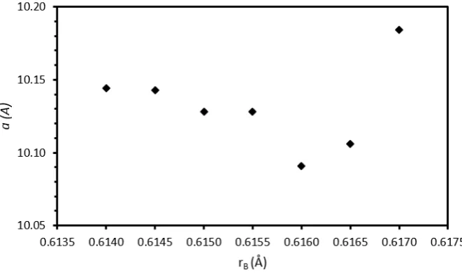
[image:5.595.39.561.650.770.2]As can be seen from Table 1, at the monoclinic-tetragonal transformation there is sharp decrease in the unit cell a parameter. With increasing Cs and Ti substitution (for Ba and Fe respectively) there is a general trend of increasing a parameter after an initial decrease resulting from the change in symmetry (see Figure 2). The b lattice parameter shows a general decreasing trend with increasing Cs and Ti substitution. The ionic radii of Cs and Ba in eight-fold coordination are 1.74 and 1.42 Å respectively 21, therefore the general trend of increasing unit cell volume is indicative of increasing amounts of Cs being incorporated in the structure, see Table 1.
Figure 2: Variation of a lattice parameter with average B-site ionic radius.
Figure 3: Representative backscattered electron micrographs of “well-sintered” regions of cold uniaxially pressed hollandites, Ba1.2-xCsxFe2.4-xTi5.6+xO16: a) x = 0.0, b) x = 0.1, c) x =
0.2, d) x = 0.3, e) x = 0.4, f) x = 0.5 and g) x = 0.6.
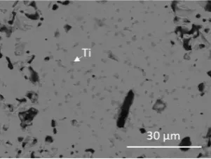
Figure 4: Typical rutile cluster in Ba0.9Cs0.3Fe2.1Ti5.9O16.
[image:7.595.222.373.473.587.2]optimised. A possible method of improving retention of the Cs inventory would be to hot isostatically press samples, the use of a hermetically sealed can prevents Cs volatilisation.
Figure 5: Cs content in synthesised hollandites (wt %): target (black squares) and as
determined by XRF (open diamonds).
3.1Mössbauer spectroscopy
[image:8.595.131.462.120.318.2]Table 2: Mössbauer parameters for Ba1.2-xCsxFe2.4-xTi5.6+xO16 hollandites: = isomer shift,
= quadrupolar splitting and = full width at half maximum.
x (mm.s-1) (mm.s-1) (mm.s-1)
0 0.385(1) 0.551(2) 0.180(1) 0.1 0.388(1) 0.541(2) 0.176(2) 0.2 0.380(2) 0.542(3) 0.187(2) 0.3 0.385(2) 0.522(3) 0.172(2) 0.4 0.386(2) 0.517(3) 0.174(2) 0.5 0.388(2) 0.514(3) 0.172(2) 0.6 0.391(2) 0.517(4) 0.176(3)
The hyperfine parameters show variation with Cs substitution similar to the refined lattice parameters. The quadrupolar splitting follows a generally decreasing trend and this implies that the Fe site is becoming progressively less distorted from ideal octahedral symmetry.
The Mössbauer data are in agreement with the results previously reported by Leinekugel-le-Cocq et al. for a hollandite with the composition Ba1Cs0.28Fe0.82Al1.46Ti5.72O16.
Leinekugel-le-Cocq et al determined that Fe was present in the Fe (III) oxidation state 2. Fe (III) in octahedral co-ordination has also previously been observed in Fe-bearing hollandites by both Birchall et al (1969) for Cs and Cs-Sc containing ferric hollandites (Cs0.7Fe0.7Ti3.3O8)
and by Drofenik and Hanžel (1982) for K containing ferric hollandites (K1.45Fe1.45Ti6.55O16) 12,13. However, our results are somewhat in contrast to those reported by Nguyen et al (2005)
who found that Fe3+ occupied two distinct sites in ferric Ba-Cs hollandite structures (Ba1Cs0.28Al1.46Fe0.82Ti5.72O16, the most analogous to the compositions studied in this
Figure 6: Room temperature Mössbauer spectra of Cs substituted Fe-hollandites
[image:10.595.229.373.69.643.2]3.2X-ray absorption spectroscopy
Figure 7a shows the measured XANES spectra of the hollandite samples and standards (FePO4,
NaFeSi2O6, Fe2Al9O6(SiO4)4(O,OH)2) and FeCO3). Figure 7b shows a detailed view of the
pre-edge region of the XANES spectra in Figure 7a.
Figure 7: (a) Fe K-edge XANES spectra of hollandite samples and standards; (b) detail of
pre-edge XANES features. FePO4 (i), NaFeSi2O6 (ii), Fe2Al9O6(SiO4)4(O,OH)2) (iii), FeCO3
(iv), Ba0.6Cs0.6Fe1.8Ti6.2O16 (v), Ba0.8Cs0.4Fe2Ti6O16 (vi), BaCs0.2Fe2.2Ti5.8O16 (vii),
Ba1.2Fe2.4Ti5.6O16 (viii).
Fe K edge XANES data show that the predominant oxidation state of Fe in all hollandite samples is Fe (III). The pre-edge feature is attributed to quadrupolar transitions from bound Fe 1s to 3d states or dipolar transitions from bound 1s to 4p states 15. The 1s to 3d transition is formally forbidden by the dipole selection rule l = ±1. This rule is relaxed when Fe is located in a non-centrosymmetric co-ordination environment resulting in 4p-3d mixing and intensified absorption22. Although the weighted mean centroid position and height of the pre-edge feature are related to site symmetry, it has been shown that these features show a linear relationship for average co-ordination number, assuming Fe oxidation state is constant 15. As can be seen there is no significant variation in the pre-edge height or position of this feature for the hollandite samples, as a function of composition and it can therefore be concluded that Fe exists in the same co-ordination environment in all hollandite samples.
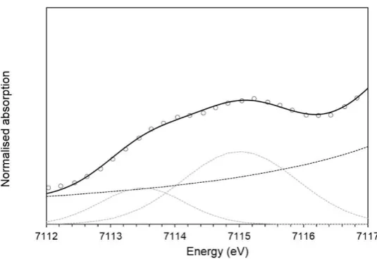
The measured XANES spectra were fitted according to the method described by Wilke et al 15.
Figure 7: Fitting of XANES features for BaCs0.2Fe2.2Ti5.8O16 sample measured in fluorescence
[image:12.595.85.513.369.500.2]mode. Gaussian (dashed grey lines) and arctangent (dashed black line) functions were used to fit the pre-edge and background features respectively. Data are shown by open symbols, fit is shown by a solid black line.
Table 3: Integrated pre-edge intensity and energies of fitted Fe XANES spectra
Sample Energy (eV) (± 0.3) Integrated pre-edge intensity (± 0.03) Ba1.2Fe2.4Ti5.6O16 7114.5 0.06
BaCs0.2Fe2.2Ti5.8O16 7114.6 0.08
Ba0.8Cs0.4Fe2Ti6O16 7114.4 0.06
Ba0.6Cs0.6Fe1.8Ti6.2O16 7114.6 0.06
FeCO3 7112.8 0.07
Staurolite 7112.9 0.19
NaFeSi2O6 7114.3 0.08
FePO4 7114.3 0.33
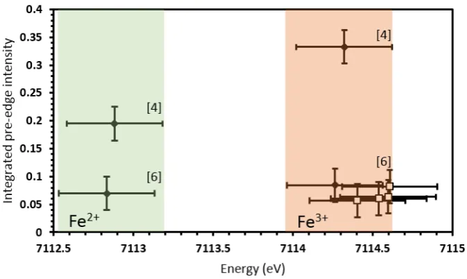
Figure 9: Fe co-ordination environment as speciated by pre-edge energy position and
integrated pre-edge intensity in Fe K edge XANES. Solid diamonds show data for standards Fe2Al9O6(SiO4)4(O,OH)2), FeCO3, FePO4 and NaFeSi2O6. Open squares show data for
synthesised hollandites.
4. Conclusions
Ferric hollandites in the system Ba1.2-xCsxFe2.4-xTi5.6+xO16 were synthesised with Cs substitution
for Ba ranging from 0.0 < x < 0.6 formula units. XRD analysis has found that there is a phase transition from a monoclinic to tetragonal unit cell upon the substitution of Cs with a general trend of increasing lattice parameters with increasing substitution of Cs consistent with the incorporation of Cs into the hollandite structure. Although increased amounts of Cs were incorporated into the hollandite structure it was evident from XRF analysis that a significant portion of the Cs inventory was volatilised during synthesis and that if retention were to be improved a different synthesis procedure, such as hot isostatic pressing, is required. 57Fe Mössbauer and XANES analysis has confirmed that all Fe within the synthesised hollandites is in the Fe (III) oxidation state and is randomised across a single, six-fold co-ordinated crystallographic site within the structure.
Acknowledgements
[image:13.595.131.468.76.277.2]References
1 P. D. Wilson, The Nuclear Fuel Cycle: From Ore to Waste, Oxford University Press, Oxford, 1st edn., 1996.
2 A. Y. Leinekugel-le-Cocq, P. Deniard, S. Jobic, R. Cerny, F. Bart and H. Emerich, J. Solid State Chem., 2006, 179, 3196–3208.
3 W. E. Lee, M. I. Ojovan, M. C. Stennett and N. C. Hyatt, Adv. Appl. Ceram., 2006,
105, 3–12.
4 A. Byström and A. M. Byström, Acta Crystallogr., 1950, 3, 146–154.
5 A. E. Ringwood, K. D. Reeve, D. M. Levins and E. J. Ramm, in Radioactive Waste Forms for the Future, eds. R. C. Ewing and W. Lutze, North Holland Physics Publishing, New York, 1988, pp. 233–335.
6 W. Sinclair, G. M. McLaughlin and a. E. Ringwood, Acta Crystallogr. Sect. B Struct. Crystallogr. Cryst. Chem., 1980, 36, 2913–2918.
7 M. L. Carter and R. L. Withers, J. Solid State Chem., 2005, 178, 1903–1914.
8 J. E. Post, R. B. Von Dreele and P. R. Buseck, Acta Crystallogr. Sect. B Struct. Crystallogr. Cryst. Chem., 1982, 38, 1056–1065.
9 N. C. Hyatt, M. C. Stennett, S. G. Fiddy, J. S. Wellings, S. S. Dutton, E. R. Maddrell, A. J. Connelly and W. E. Lee, Mater. Res. Soc. Symp. Proc., 2006, 932.
10 V. Aubin-Chevaldonnet, D. Caurant, a. Dannoux, D. Gourier, T. Charpentier, L. Mazerolles and T. Advocat, J. Nucl. Mater., 2007, 366, 137–160.
11 N. Nguyen, a. Ducouret, F. Studer, V. Aubin, D. Caurant, D. Gourier and J. M. Costantini, Hyperfine Interact., 2005, 166, 489–493.
12 M. Drofenik and D. Hanzel, Mater. Res. Bull., 1982, 17, 1457–1460.
13 T. Birchall, N. N. Greenwood and A. F. Reid, J. Chem. Soc. A Inorganic, Phys. Theor., 1969, 2382.
14 D. G. Rancourt and K. Lagarec, "Recoil, Mössbauer Spectral Analysis Software
for Windows", 1998.
15 M. Wilke, F. Farges, P. E. Petit, G. E. Brown and F. Martin, Am. Mineral., 2001, 86, 714–730.
16 B. Ravel and M. Newville, Phys. Scr., 2005, 1007.
17 R. W. Cheary, Acta Crystallogr. Sect. B Struct. Sci., 1986, 42, 229–236.
18 F. C. Mijlhoff, D. J. W. IJdo and H. W. Zandbergen, Acta Crystallogr. Sect. B Struct. Sci., 1985, 41, 98–101.
19 L. A. Bursill and J. Kwiatkowska, J. Solid State Chem., 1984, 52, 45–52.
20 X. J. Wu, F. H. Li and H. Hashimoto, Acta Crystallogr. Sect. B Struct. Sci., 1990, 46, 111–117.
21 R. D. Shannon, Acta Crystallogr., 1976, 32, 751–767.