Int. J. Electrochem. Sci., 8 (2013) 7713 - 7723
International Journal of
ELECTROCHEMICAL
SCIENCE
www.electrochemsci.org
Evaluation of The Cathodic Protection Applied to Steel
Embedded in the AAS Using the Finite Element Method
W. Aperador1,*, A. Delgado1,2, J. Carrillo1
1
Departament of Engineering, Universidad Militar Nueva Granada, Carrera 11 No. 101-80, Fax:+57(1) 6343200, Bogotá, Colombia.
2Escuela Colombiana de Ingeniería – Julio Garavito, Bogotá, Colombia. *
E-mail: [email protected]
Received: 20 April 2013 / Accepted: 10 May 2013 / Published: 1 June 2013
In the present work using mortar samples of slag activated with alkaline solution (AAS) to which chloride induces a corrosive process by entering the chloride ion. After that cathode protection was applied to steel bars and then applied cathodic protection on steel bars ASTM A706 seismic resistant earthquake resistant embedded in the mortar with and without process of carbonization. For comparative purposes, ordinary Portland cement mortars were used (OPC) and exposed to the same experimental conditions.By means of the design through the numeric method based on finite elements (FEM) and the method of finite difference (FDM) applied to the cathodic protection and the electrochemical system, consists consisting of a simple geometry using the finite difference method (FDM), the influence of the conductivity was investigated on the cathodic protection in the of AAS mortars AAS. The study shows as a result was investigated, obtaining that the carbonation process has a positive influence in the conductivity favoring the cathodic protection.
Keywords: cathode protection, chloride ion, AAS, finite element method.
1. INTRODUCTION
preventive actions by expensive repairs or inclusive or even reach radical decisions as the demolition of the structures that have been affected.
The cathodic protection (CP) is considerate as the only one rehabilitation technique that has demonstrated avoid the corrosion process in the contaminated bridge decks with the salinity of the environment [4-6]. The CP is very useful due that extents the service life of the steel pipes; in special the buried that are used in the transport of oil and gas as well as in structures offshore oil drilling, hoofs seagoing vessels, marine pilings, water tanks and chemical recipients. The concept behind the CP consists in displace the potential of a metal electrode to a value more negative where the corrosion velocity is low enough inhibiting to the corrosive process [7].
In the case of structures base on concrete, is affected by the exposition to aggressive saline environments, the convectional procedure of reparation implies the elimination of the concrete armors contaminated with chlorides; cleaning in the whole perimeter, replacement of the affected concrete and the application of some kind of protection which avoid new repairs [8]. This process is very expensive from the economic standpoint and harmful for both workers and the environment.
There is a very special type of Alkali-activated slag concrete (AAS). This type of concrete is conformed by a mixture of ground granulated slag, fine aggregates, thick aggregates and alkali solution (sodium silicate) in the required quantity for the mixture. Those have been studied object by a large number of researchers in the field of new construction materials [9]. The AAS present technologic and economic advantages in comparison with the traditional Portland cements (OPC), among which stand: lower hydration heat, low permeability, greater high temperature resistance, greater resistance to chemical attack and improvement of the mechanical resistance. Likewise, present some disadvantages such as: faster curing, more formation of microfissures and resistance variability [10]. The reinforced concrete is one of the materials for construction more versatile, for its service properties and wide variety of applications, and low cost. Nevertheless, the rebar in this type of structures has susceptibility to corrode decreasing considerably the service life of the composed material concrete-steel [11-15].
The corrosion in the rebar is one of the causes more likeable of the wear of the concrete structures. In the Portland concretes the free chloride ions trigger corrosion process by pitting; that attack directly the passive layer of the steel and impedes its regeneration.
The aim of this work is applies the cathodic protection (CP) in each system conformated by Alkali-activated slag concrete and exposed to the solution with chlorine ions and determinate its behavior against aggressive environment. Furthermore, a mathematical model was applied based on the finite element method to study the behavior of the CP embedded in AAS and OPC mortars.
2. EXPERIMENTAL PROCEDURE
Fort the development of the present study was used: a Colombian steelmaker slag of blast furnace with a chemical composition of 33.7% SiO2, 12.8% Al2O3, 45,4% CaO, 0,5% TiO2 and 1.00%
MgO as cementitious; The basicity coefficient (CaO+MgO/SiO2+Al2O3) and the quality
solution with concentration of 5% Na2O expressed as percentage by weight of slag. The used
aggregates correspond to river sand with density of 2410 kg/m3 and 2.9% of absorption. The OPC mixtures used commercial Portland cement without additive. The conformation of the mortar mixtures in both cases content 400 kg/m3 of cementitious material dosage. It was assummed that the relation water/cement and solution water+ activating/slag are equivalent, in both cases the relation was 0.4 [16-18].
It was managed mortars mixtures with Alkali Activated Slag without the carbonation process (AAS) and Alkali Activated Slag completely carbonated (AASC). For the process of carbon dioxide inclusion was used in a carnation chamber at controlled conditions (3%CO2, 65% relative humility and
20ºC of temperature); for the OPC mortars the conditions were similar to AAS: mortar of ordinary Portland cement without carbonation (OPC) and mortar of ordinary Portland cement carbonated (OPCC). The working conditions for each mixture were:
Mortar subjected to accelerated carbonation and chloride ion attack. The concretes were immersing in a solution with 3.5% of analytical sodium chloride Panreac PA131655.1211 NaCl 99.0%) for 60 days, subsequently was applied a cathodic protection. The purpose is to begin the process of corrosion with the carbonation; then with the chlorine is performed the propagation process and with the cathodic protection is generated the anticorrosive defense.
Mortar without accelerated carbonation, with chloride ion exposition and application of cathodic protection.
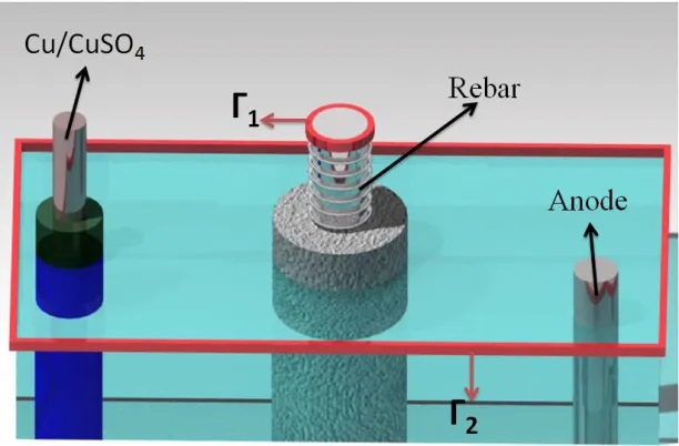
For the tests were made cylindrical specimens with 12.5 mm of diameter by 25 mm height, with a ASTM A 706 structural steel bar placed in the center of the specimen. The rebar diameter is 6.15 mm. The used electrochemical cell is composed by an auxiliary electrode of stainless steel, a reference electrode of Cu/CuSO4 and as a working electrode the ASTM A 706 structural steel with an
[image:3.596.146.452.529.730.2]exposed area of 10 cm2 [19]. The mounting for the cathodic protection implementation is shown in the figure 1. The impressed current applied on the auxiliary electrode (Anode AISI 304 SS) in each one of the cases was 55x10-6 A cm-2.
3. RESULTS AND DISCUSSION
3.1 Numeric method
One of the applications of the numeric methods is to predict the behavior of the steel corrosion with a configuration of coplanar electrodes without variations of polarization effects. Analyses were limited to a one-dimensional approach in the rectangular coordinate systems. These mathematical treatments used the Poisson and Laplace equations:
x y z
f z yx 2 , ,
2 2 2 2 2 2 (1) Where x y z2 fx,y,z
2 2 2 2 2 2
[image:4.596.55.529.388.773.2]correspond to the Laplace and f
x,y,z
0 for the Poisson equation. The variational formulation for the unidimensional limit is the problem approached by the simplifying of Butler-Volmer equation [20]. Considering the physic situation that is shown in the figure 1, in where a plastic container contents the reinforced mortar and an anode situated at the corner x12.5 cm and in the y axis y12.5 cm, the boundary value of this situation is given by the equation 2:
x yf
k ,
(2)
With the boundary condition: 0
n
k en 1, y h
nk
in 2, where h
Is the function that represents the polarization curve of the embedded and immersed rebar in an electrolyte of 3.5% NaCl and f
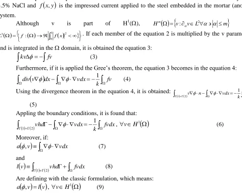
x,y is the impressed current applied to the steel embedded in the mortar (anode) system.Although v is part of H1(), Hm
v vL m
2 : and
10 2 2
: f x
f
L . If each member of the equation 2 is multiplied by the v parameter and is integrated in the domain, it is obtained the equation 3:
kv fv (3)Furthermore, if it is applied the Gree’s theorem, the equation 3 becomes in the equation 4:
div v dx vdxk fv1
(4)
Using the divergence theorem in the equation 4, it is obtained:
v n vdxk fv 12
1
(5)
Appling the boundary conditions, it is found that:
12
1
fvdx k
vdx
vhd , vH1
(6) Moreover, if:
vdx
v
a, (7)
and
2
1 vhd fvdx
v
l (8)
Are defining with the classic formulation, which means:
v l v
Finding the exact solution in two dimensions is arduous work, therefore is constructed an approximation calledN, which stands a unidimensional problem in the finite space. One part of the domain is divided in N parts and one finite dimension of sub-space H1
called CN and formed by the functioni:. Where i is a polynomial in 2(Euclidean vector space bidimensional) fori1,...,N.
The problem focuses on findingNCN, thus:
f vk v
aN, 1 , , vCN
(10)
As,i, i=1,…,N is the base of CN2. Therefore, the solution is expressed as lineal combination ofi. Reminding that one of the fundamental tasks of FEM is created and selected an adequate base, hence, if:
N M
i i i N a 1 (11)
It is defined the coefficient aias the unknown quantity to evaluate, in this manner the numeric solutions is simplified to the following expression:
2 1 1 , , , , , , dA k y x v y x f vhd dA y x v y x y y x x a N i i i i (12)In particular, although v is replaced by the base elements, then:
2 1 1 , , , , , , , , dA k y x y x f vhd dA y x y y x x y x y y x x a j N i j j i i i N
j1,..., (13) or in matrix form
2 1 2 1 1 1 1 1 1 1 1 1 1 1 1 , , 1 h y x f h y x f k a a dx y y x x dx y y x x dx y y x x dx y y x x N N N N N N N N N N N
3.2 Distributions of Isopotential Lines
Cu/CuSO4) [21]. The potential measurements were registered when the equilibrium conditions were
[image:6.596.72.529.160.665.2]achieved.
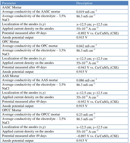
Table 1. Used design parameters, in the protection of impressed current for the embedded steel bars in mortar AAS and OPC subjected to natural carbonation and accelerated carbonation.
Parameter Description
AASC Mortar
Average conductivity of the AASC mortar 0.019 mS cm1 Average conductivity of the electrolyte – 3,5%
NaCl
86.3 mS cm1
Localization of the anodes (x,y) x12.5 cm; y12.5 cm Applied current density on the anodes 55106 A cm2
Potential measured after 49 days 0.892 V vs. Cu/CuSO4 (CSE)
Anode potential output 0.915 V
OPC Mortar
Average conductivity of the OPC mortar 0.042 mS cm1 Average conductivity of the electrolyte – 3,5%
NaCl
86.3 mS cm1
Localization of the anodes (x,y) x12.5 cm; y12.5 cm Applied current density on the anodes 55106 A cm2
Potential measured after 49 days 0.943 V vs. Cu/CuSO4 (CSE)
Anode potential output 0.915 V
AAS Mortar
Average conductivity of the AAS mortar 0.086 mS cm1 Average conductivity of the electrolyte – 3,5%
NaCl
86.3 mS cm1
Localization of the anodes (x,y) x12.5 cm; y12.5 cm Applied current density on the anodes 55106 A cm2
Potential measured after 49 days 0.952 V vs. Cu/CuSO4 (CSE)
Anode potential output 0.915 V
OPCC Mortar
Average conductivity of the OPCC mortar 0.23 mS cm1 Average conductivity of the electrolyte – 3,5%
NaCl
86.3 mS cm1
Localization of the anodes (x,y) x12.5 cm; y12.5 cm Applied current density on the anodes 55106 A cm2
Potential measured after 49 days 0.897 V vs. Cu/CuSO4 (CSE)
Anode potential output 0.915 V
resolves the established system. The approximation mathematical function used in each one of the embedded steels in the mortars is:
2
0 *
2 0 *
exp
,y r s x x s y y
x
f (15)
Where r is a factor that involves the polarization potential of the steel bar, s* is the factor which relates the anode diameter, x0 and y0 are the rectangular coordinates of the ASTM 706 steel bar
center.
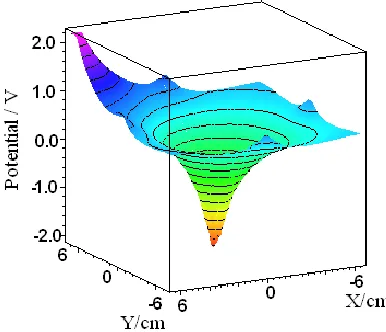
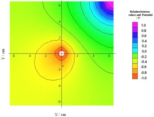
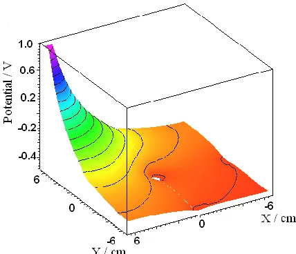
[image:7.596.200.393.316.482.2]In the figure 2 and 3 are observed the iso-potential lines distribution of the embedded rebar in an AASC mortar with a potential variation among the lines of 0.2 vs reference electrode. The bar is protected according to the criteria of potential value indicating between -0.85 and -1.0 V vs. reference electrode. In the case of AASC, the figure 2 and 3, the impressed current of 55106 A cm2 generates a potential change of 4 volts vs. reference electrode approximately indicating that the structure is protected against the corrosion. However, it is possible to observe that by applying a less impressed current quantity for the embedded steel in AASC is generated a good cathodic protection as well [22].
Figure 2. Calculation of potential distribution for AASC mortars, for a bidimensional model.
[image:7.596.185.418.537.721.2][image:8.596.158.439.164.355.2]
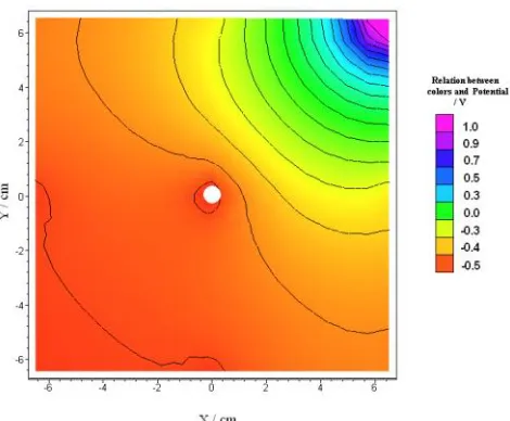
In the figure 4 and 5 is observed the calculation and the distribution of iso-potential lines of the embedded rebar in an AAS mortar, it is obtained a potential difference of 0.2 V vs. reference electrode. The cathodic protection reached in the AAS is 1 V vs. reference electrode. This result leads to stand that the impressed current protects the structure cathodically [23].
Figure 4. Calculation of potential distribution for AAS mortars using a bidimensional model.
Figure 5. Calculation of iso-potential lines distribution by rectangular coordinates for the steel bar embedded in AAS mortar.
[image:8.596.167.429.412.611.2]
Figure 6. Calculation of potential distribution for OPCC mortars using a bidimensional model.
Figure 7. Calculation of iso-potential lines distribution by rectangular coordinates for the steel bar embedded in OPCC mortar.
[image:9.596.181.417.71.247.2] [image:9.596.173.426.300.498.2] [image:9.596.191.405.555.739.2]
Figure 9. Calculation of iso-potential lines distribution by rectangular coordinates for the steel bar embedded in OPC mortar.
In the figure 8 and 9 is observed the calculation and distribution of the iso-potential lines of the embedded rebar in the OPC mortar. It is obtained a potential difference of 0.1 V vs. reference electrode. The cathodic protection indicates a potential of 1 V vs. reference electrode; this shows that with the impressed current the structure is cathodically protected [25].
4. CONCLUSIONS
Este resultado es de gran importancia en el empleo en ingeniería del proceso de protección catódica para disminuir la energía utilizada en estructuras de concreto. Adicionalmente mediante los modelos matemáticos y el cálculo FEM se permite evaluar el rendimiento de la PC usando el parámetro de la conductividad. Por último la técnica de protección catódica permite concluir que el proceso de carbonatación tiene una influencia positiva en la conductividad el cual es el parámetro de diseño que favorece la implementación de esta técnica.
The AASC mortar presents the highest conductivity value (twelve times superior tan OPCC) which is the responsible of the good cathodic protection generated in this material. The mortars OPC and AAS have a higher conductivity value (0.042 for the OPC and 0.086 for the AAS) indicating that the necessary current increases to generation of the cathodic protection. This result is of great importance to the engineering of the cathodic protection process, to decrease the used energy in concrete structures. Furthermore, using mathematical model and the FEM calculation, is allowed to evaluate the PC performance by conductivity parameters. Lastly, the cathodic protection technique allows standing that the carbonation process has a positive influence in the conductivity which is the design parameter that favors the implementation of this technique.
References
[image:10.596.181.416.68.262.2]
2. J. G Newton, J. M Sykes, Corrosion Science; 28 (1989) 1051.
3. R. D Brownea, R. Blundell, Nuclear Engineering and Design, 20 (1972), 429. 4. B. S. Wyatt, Corrosion Science, 35 (1993) 1601.
5. A. M Hassanein, G. K Glass, N. R Buenfeld, Cement and Concrete Composites, 24 (2002) 159. 6. Xu Jing, Yao Wu, Construction and Building Materials, 25 (2011) 2655.
7. J.H Morgan, Journal of Electroanalytical Chemistry and Interfacial Electrochemistry, 118 (1981) 251.
8. N. Hackerman, Langmuir , 3 (1987) 922.
9. S. Caijun, Cement Concrete Res, 26 (1996) 1789.
10.S. Caijun, Q. Jueshi, Conservation and Recycling, 29 (2000) 195. 11.M. Holloway, J. M Sykes, Corrosion Science, 47 (2000) 3097.
12.A. Allahverdi, B. Shaverdi, B, Kani, International Journal of Civil Engineering, 8 (2010) 304. 13.W. Aperador, R. Vera, A. M. Carvajal, Int. J. Electrochem. Sci., 7 (2012) 12870.
14.F. Puertas, Materiales de Construcción, 45 (1995) 53.
15.E. P. Reyes-Diaz, E. Maldonado, F. Almeray, D. M. Bastidas, M. Baltazar, J. Chacón, A. Martínez-Villafañe, J. M. Bastidas, C. Gaona Tiburcio, Int. J. Electrochem. Sci, 6 (2011) 1892.
16.16. W. Aperador, R. Mejía de Gutiérrez, D. M Bastidas, Corrosion Science, 51 (2009), 2027. 17.W. Aperador, E. Delgado, E. Vera, Revista Ingeniería de Construcción, 26 (2011) 81.
18.W. A Chaparro, J.H.B Ruiz, R De Jesús Torres Gómez, Materials Research, 15 (2012) 57. 19.ASTM A706/A706M - 09b Standard Specification for Low-Alloy Steel Deformed and Plain Bars
for Concrete Reinforcement, Vol. 1.04, Filadelfia (EE.UU.): American Society for Testing and Materials, (2009).
20.R. Montoya, W. Aperador, D.M. Bastidas, Corrosion Science, Volume 51, Issue 12, December 2009, Pages 2857–2862
21.NACE Standard RP0290-90 (1990) Item No. 53072.
22.W. Aperador; A. Delgado, J. Bautista, Ingeniería y Universidad, 16 (2012) 77.
23. G.T.Parthiban, K.Bharanidharan, D.Dhayanand, Thirumalai Parthiban, N.Palaniswamy, V.Sivan, Int. J. Electrochem. Sci., 3 (2008) 1162 – 1168.
24. A.S.S.Sekar, V.Saraswathy, G.T.Parthiban, Int. J. Electrochem. Sci., 2 (2007) 872 – 882. 25. Ha-Won Song, Velu Saraswathy, Int. J. Electrochem. Sci., 2 (2007) 1- 28.