Validation of a fully integrated platform and disposable
microfluidic chips enabling parallel purification of genome
segments for assembly
M. Kersaudy-Kerhoas1, F. Amalou 1, Y.Liu 1, A. Che2, J. Kelly2, M.P.Y. Desmulliez 3
and W. Shu 1,a)
1 Institute of Biological Chemistry, Biochemistry and Bioengineering, Heriot-Watt University,
Edinburgh, United Kingdom.
2 Gingko Bioworks, 27 Drydock Avenue Floor , Boston, MA, USA
3 Institute of Sensors, Signals and Systems, Heriot-Watt University, Edinburgh, United
Kingdom.
Abstract
Recent progress in the field of genetic engineering has opened up the door to novel synthetic
biology applications. Microfluidic technology has been emphasized as a key technology to
support the development of these applications. While several important synthetic biology
protocols have been developed in microfluidic format, no study has yet demonstrated on-chip
error control. In synthetic biology protocols, the purification phase is a critical error control
process which enhances the reliability of the genome segment assembly by removing
undesired oligos. In this context, we report the design and characterization of a fully
integrated platform, demonstrating the purification of up to 4 genome segments in parallel,
prior to their off-chip assembly. The key innovation of this platform is the decoupling control
strategy which eliminates the need to integrate expensive components onto the microfluidic
device, enabling lower cost, disposability and rapid operation. Unlike most microfluidic chips
where fluid connector plugs are needed to connect external pumps, this approach is plug-less
and the chips are simply connected to the control breadboard by clamping. Furthermore the
passive chip is isolated from the active control layer thereby eliminating the risk of
sample-to-sample contamination in the reusable parts. As a validation of this fully-integrated system,
the parallel on-chip purification of genome segments was demonstrated with purity up to
20% superior to the bench controls, proving thereby the suitability of the platform for
synthetic biology applications.
I. Introduction
Synthetic Biology encompasses techniques and methods used to re-engineer biological units
such as cells or organisms (Carr and Church 2009). To achieve this, synthetic biology
engineers have created standardized biological units: bioparts or biobricks which assembly
can be changed on demand using a standard, predictable, and therefore more reliable
protocol. By being able to tune living systems, or create new synthetic biological systems, the
production of materials such as medicines or biofuels from biological living organisms could
be transformed or dramatically improved. In that respect synthetic genome segment assembly
is currently used for the optimisation of various enzymatic pathways (Boehm et al. 2013;
Smolke and Silver 2011). As an example, the variation of major transcriptional regulators to
perturb metabolisms is deemed to increase the yield of bacteria producing biofuels (Colin et
al. 2011).
The design of genetic systems involves the synthesis and assembly of genome segments.
While the oligo synthesis is performed by organic chemical reactions, a greater variety of
protocols exist for joining or assembling larger DNA segments (Carr and Church 2009).
Among others, ligation allows pooling assembly organisation and is the fastest method
compared to serial, parallel or hierarchical assembly (Carr and Church 2009). At the heart of
the ligation process is the use of short specific overhangs (commonly referred to as “sticky ends”, usually 2 to 4 nucleotides) and a DNA ligase enzyme to assemble DNA segments.
After or during assembly, some kind of error control needs to be put into place to remove
unwanted or surplus oligos from the reaction mix and improve the reliability of the gene
synthesis. This purification phase itself has also been reported to considerably enhance the
reliability of the DNA assembly (Tian et al. 2004) and is the targeted application of the
disposable chip presented in this article.
alteration needs automation and scale-up. Current mainstream technologies for automation
involve conventional liquid handling robots which tend to be expensive. However, a series of
new technologies, namely DNA microchips and microfluidic technologies have emerged in
the last decade as a smart alternative to existing conventional technology (Fu et al. 2002; Wu
et al. 2009a). These platforms allow bioengineers (1) to go beyond the current throughput
threshold in genome sequence assembly, (2) to provide reproducible and reliable processes,
and (3) to reduce costs of failure and repeats due to human errors. To address these
challenges, microfluidic platforms offer rapid and practical automation fully compatible with
existing laboratory infrastructures such as liquid handling robots and microplate standards.
Hence, microfluidic tools are highly desirable for automating biological and chemical
protocols in order to avoid human errors, cross-contamination and lengthy procedures (Gulati
et al. 2009; Szita et al. 2010; Vinuselvi et al. 2011). In comparison to automated liquid
handling robots, microfluidic systems also offer great advantages in parallelisation,
throughput, miniaturisation and cost.
Several microfluidic platforms for biological protocol automation have been developed over
the last decade (Balagadde et al. 2005; Gomez-Sjoeberg et al. 2007; Hong and Quake 2003;
Lee et al. 2010; Wu et al. 2009b). Microfluidic large scale integration (µLSI) was developed
using pneumatically controlled micromechanical valves and pumps, enabling highly complex
biological automation in parallel (Hong and Quake 2003). The microfluidic valves are
manufactured using multilayer soft-lithography with superimposed polydimethysiloxane
(PDMS) layers for manipulating liquids and gases (Squires and Quake 2005; Xia and
Whitesides 1998). The gas in the control channel applies a pneumatic pressure which bends
the elastomer membrane over the flow channel in order to precisely control the flow of
liquids. Similarly, microfluidic latches were developed using pneumatic vacuum (Grover et
been demonstrated for synthetic biology applications. Zhou and colleagues demonstrated the
synthesis and assembly of multiple DNA sequences in a microfluidic picoarray (Zhou et al.
2004). Kong et al demonstrated a parallel gene synthesis in 500 nL chambers which
dramatically reduced by two orders of magnitude the volumes of reagents used (Kong et al.
2007). Multiplex gene synthesis have also been achieved using adapted protocols partly
performed on DNA microchips (Tian et al. 2004), (Richmond et al. 2004). A platform using
electrowetting as the actuation method has demonstrated parallel DNA ligation in a 2.1µL
reaction chamber (Lin et al.). Another PDMS/glass chip assembly has recently demonstrated
successful DNA ligation with optimised protocol timing (5 min) compared to its benchtop
counterpart (4h) (Ko et al.). However, these devices did not incorporate DNA error correction
protocol.
Despite interesting characteristics, the use of PDMS presents several disadvantages: (i) high
permeability of the material means that some specific design must be implemented to
counteract the fast evaporation of small volumes of liquid (Kong et al. 2007), (ii) its
compliance induces large variations in device performance (ie flow rate variability) and
consequently PDMS is rarely a material of choice in industry unless for use of specific properties such as in Quakes’ valves (Becker). Although practical in terms of
rapid-prototyping and its low cost, the use of PDMS in research laboratories has been largely
questioned in recent years, and several alternatives providing higher Young’s modulus have
been proposed (Sollier et al. 2011).
Packaging is also a serious commercialisation issue for microfluidic systems (Webb et al.
2009), and for all of the techniques described above, common features such as direct plugs on
chip for fluid introduction or pneumatic control bonded on chip are required. For some
systems, up to hundreds of tubing connections have to be plugged onto a microfluidic chip
prone to human errors. In addition, fluidic connectors plugged directly on the chip hinder the
direct loading or recovery of products by manual or robotic liquid systems. There is a real
need for microfluidic platforms offering greater compatibility with high throughput robotic
liquid systems for full automation.
To address these challenges, an alternative approach, named ‘Clamp n’Play’ is proposed. The
Clamp n’Play approach is a plug-less clamped-based microfluidic chip, for full-scale
biological protocol automation, using an integrated platform system with a user-friendly
interface. Modular platforms based on pneumatic fluid actuation have been demonstrated in
the past but they often integrate passive and active layers in one monolithic block. Some
decoupled concepts have been proposed. For example, a modular platform and chips made of
PDMS and silicon allowed the separation of actuators (active chip) from reactor (passive
chips)(Shaikh et al. 2005). However, the fluid circulates in the passive as well as the active
re-usable chip, therefore contamination may occur in the non-disposable parts of the system.
Clamping systems have been in use in several microfluidic groups (Skafte-Pedersen et al.
2013), although no fully integrated platform with electro-mechanical actuators has been
reported and validated with a synthetic biology application. The unique features of our
approach are the combination of the following: (i) the separation or decoupling of the
microfluidic device from its flow control components and microactuators allowing
modularity, (ii) the isolation of the reaction layer from the actuation layer, eliminating sample
contamination in the reusable parts (iii) high-throughput capabilities and (iv) compatibility
with automated pipette loading. The functionality of the platform is successfully validated via
the parallel purification of genome segments, using a 4-channel chip, prior to the complete
assembly of a recombinant plasmid.
2. Materials and Methods
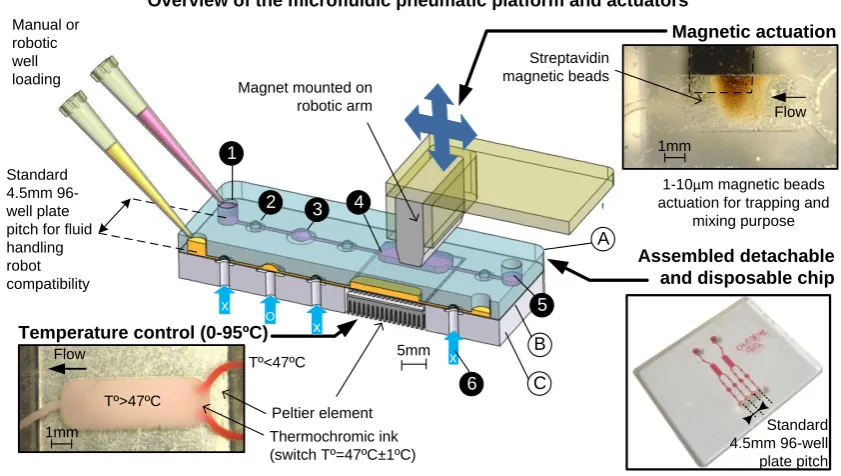
The decoupling concept, illustrated in Fig.1, employs a multi-layer, but physically detachable
system. The chip contains a rigid layer (A) for the accurate alignment of the chip with the
underlying platform, combined with an elastic and deformable layer (B) acting as a
membrane for closing valves via pneumatic actuation as well as sealing the chip and isolating
it from the platform. The membrane is flexible enough to bend and close the valve fully, yet
strong enough to sustain repeated actuations. The flow inside the microfluidic channels is
accurately controlled by a separate underlying control platform (C) which integrates an array
of pneumatic microactuators for actuating the various elastic membranes of the system and
magnetic and thermal actuators for performing biological reactions. No tubing connection is
necessary on the microfluidic chip and the disposable passive part is simply clamped on a
layer of silicone O-rings (Polymax, UK) embedded in the integrated control platform (not
shown in Figure 1). Silicone O-rings allow a good seal at each of the chip-to-platform
pneumatic connections. For scale-up purpose, the o-ring layer may be replaceable by a
moulded elastomer layer. By decoupling the functions pertinent to the chip and control
system, a simple low-cost polymeric chip can perform complex biological protocols
involving pumping, mixing, reaction, and purification in a fully automated way.
2.2. Purification chip design
The architecture of the purification chip consists of four independent channels (250 µm
width, 39 mm length), each having (i) an input and output well (4 mm in diameter, 4 mm
depth), (ii) a pump featuring two valves and an actuation chamber, (iii) a reaction chamber (9
mm x 3 mm x 0.2 mm) and (iv) a back valve to isolate the reaction chamber from the output
well. To make the chip fully compatible with existing fluid handling robotic solution, input
and output holes or wells have been spaced with the standard 96-well plate pitch (Fig 1,
bottom-right insert). The reservoirs on the microfluidic chip can be prefilled using manual or
number of channels was kept to four for simplicity and allowing for the parallel purification
of the three genome segments (c.f. Biological Materials), plus a negative control. The chip
footprint allows potential for scaling-up the number of channels to accommodate 16
channels. The chip fabrication is described in supplementary material.
2.3. Pneumatic, thermal and magnetic actuators and control
Accurate control of the micro-actuators is essential to the overall performance of the
microfluidic device. In this study, compressed air actuators have been chosen for their
maximal force and displacement. The platform itself includes the pneumatic channel layers,
which have been cut in three 2mm thick PMMA layers bonded using Epoxy glue. This unit
fits on a larger base with threaded ports to accommodate air connectors. This base is itself
fixated on an optical table for ease of use and great stability. The electrovalves (D123201,
Dynamco, US) placed on each side of the base were controlled via a Data Acquisition (NI
cDAQ-9172, DAQ-9403) Card (NI, USA) and fed with 2 bar compressed air redistributed to
the platform via several permanently attached tubing segments. Using the decoupling
concept, other microcomponents can be added to the control platform without raising the cost
of the disposable plastic chip. A Peltier device (ThermaTec HtHot, Melcor, UK) measuring
6mm x 6mm was mounted with a thermo couple (Labfacility, Farnell, UK). The Peltier
device and thermo couple were placed below the reaction chambers to provide a specific
temperature profile. Similarly, a magnetic control device was mounted on the platform for
mixing and trapping purpose. Fig.1 shows the integration of a strong magnet on a robotic arm
above the reaction chamber. Streptavidin coated magnetic beads (NEB, USA) were pumped
into the reaction chamber with a conventional pumping cycle and trapped there via the
placement of the magnet close to the chamber. The use of the magnetic beads is multifold.
The motion of magnetic beads inside the reaction chamber increases the mixing and they
automate protocols and control in parallel the thermal profile, magnetic actuation and
pumping, a custom-made Labview algorithm (LabVIEW 2008, NI) and a user-interface were
developed. A snap-shot of the user-interface panel can be seen in supplementary information.
To assess the performance of the control platform and chip, a digital USB microscope
(Dinolite, Big C, USA) was placed above the device to visualise real-time variations of the
flow.
2.5. Biological Materials
For the genome segment assembly and purification experiments, DNA inserts and vectors,
oligos and reagents were supplied by Gingko Inc. (Boston, USA) which included: (i) The
high copy BioBrickTM assembly pSB1C3 plasmid (Che 2008) predigested with EarI used as a “backbone” vector for the assembly and carrying chloramphenicol resistance (ii) inserts
coding for the green fluorescent protein (GFP) or red fluorescent protein (RFP), (iii) 4 part
linkers or overhangs, and 4 purification oligos. Additionally, 15 to 30 µL of streptavidin
coated magnetic beads solution (NEB, USA) with a diameter of 1µm were used for DNA
capture during the purification experiment. NEB 10-beta competent E.Coli cells (NEB, USA)
were used for the transformation of the genome assembly obtained and the verification of the
functionality and purity of the off-chip and on-chip protocols. The high efficiency
transformation protocol suggested by the manufacturer was followed. Cells were plated on
Lysogeny broth (LB) Agar Plate with chloramphenicol (Technova, USA) and cultured for
approximately 12 hours (overnight) at 37ºC. After 12 hours, plates were removed from the
incubator and placed in a refrigerator for 4 hours. This step increased the fluorescence of the
colonies. Colonies on each plate were inspected under UV light and counted. All cells visible
on the plate carry chloramphenicol resistance, which mean they have been successfully
transformed with the plasmid. Successful purification and final assembly of plasmid vector
modified strain (green or red colonies). Gel electrophoresis was first considered for a direct
quantification of various DNA segment levels in and out of the chip. However, the detection
of small levels of DNA segments was found be impossible to obtain, while a single plasmid
can successfully transform one single cell. Therefore, the success of the purification was
verified indirectly by establishing the ratio of colonies with the correct phenotype versus the
total number of colonies in the plate after assembly. For illustration, a 50% ratio corresponds
to half of the cell population being transformed by a plasmid exhibiting the antibiotic
resistance and the modified strain (successful purification and ligation), while the other half
of the population is exhibiting only the antibiotic resistance (unsuccessful purification leads
to failed ligation between the plasmid backbone and RFP or GFP parts).
2.6. Genome segment assembly and two-part purification
In order to demonstrate the full functionality of the chip, the parallel purification of several
genome segments was demonstrated and validated through the assembly of a plasmid
backbone and a part coding for the red or green fluorescent protein, (RFP or GFP) as
presented in Fig.2A. The pre-assembly, two-step purification and final assembly are briefly
described. The first part of the assembly consists of a ligation to combine RFP and GFP parts
with part linkers. This step is performed off-chip as described in (Che et al. 2012). This is
followed by a two-step sequential purification of the pre-assembled parts. The purpose of the
purification is to wash and remove the unwanted or unbound oligos from the pre-assembled
part mix. In a first instance, purification oligos and magnetic beads bind to one end of the
pre-assembled parts (RFP or GFP parts and part linkers) and are retained via magnetic
actuation in the reaction chamber, while unwanted and unbound oligos (part linkers) are
washed away. In the second purification step, purification oligos and magnetic beads bind to
the other end of the pre-assembled part and the remaining unbound oligos are washed away.
2.7. On-chip purification protocol
The microfluidic purification protocol detailed in Fig 2.b. is carried out in two chips to avoid
contamination between the two steps. The second step of the on-chip purification protocol is
identical to the first one but for two points. Firstly, the ligation mix was replaced by the
elution product from the first step of the purification protocol and the purification oligos are
different. Following the two-step microfluidic purification, a ligation reaction combines the
purified plasmid and parts (GFP or RFP coding parts) into recombinant DNA which is
transformed into competent E.Coli cells as described in the biological materials section. In
parallel to all microfluidic experiments, bench-top controls using conventional bench fluid
handling procedures such as pipettes and plate heaters were performed to provide
performance comparison. For a fair comparison, the bench protocol followed closely the
microfluidic protocol, using the same reagents volumes and waiting time. A negative control
consisting of water was used in all experiments to verify the risk of contamination across the
channels.
3. Results and discussion
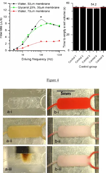
3.1. Flow rate measurements
The effects of the pneumatic actuation frequency, fluid viscosity and thickness on the
membrane on the flow rate produced were investigated. For this purpose, chips comprising
two inlets, one outlet and a reaction chamber (as shown in the photograph insert in Figure 1)
were fabricated. The chips were loaded with either water mixed with food dyes for
visualisation or with 20% glycerol (V/V) (Sigma-Aldricht, UK) in water to assess the effect
of liquid viscosity on the pumping performance. Investigating the chip performance under
different viscosity is especially important for biological applications where products may be
pumping flow rate as a function of the pumping frequency for different configurations. The
highest pumping rate of 10 µLs-1 was achieved for a pumping frequency of 100Hz, a
membrane thickness of 50 µm and water. Above 100 Hz, the flow rate decreases as the
membrane does not have the time to close properly the cavity during the pulse. Additionally
the optimal frequency is also restricted by the solenoid valve response time, which was 9 ms
for 111 Hz (Figure 3a). The same set-up was tested with a solution of glycerol in water
(20%). Glycerol is commonly used in biological protocols, and we wanted to demonstrate the
possibility to pump this material through the same system. The higher viscosity in the latter
case reduced the flow rate to 8 µL/s and the optimal frequency was slightly shifted (110 Hz).
However, due to a small data set, it is impossible to conclude whether this flow rate
difference seen between the water and 20% glycerol mixture is statically significant and
generalise this observation. The same chip design was tested with a thicker membrane (70
µm), however, the flow rate performance of the chip dropped dramatically below 3 µLs-1. For
the remainder of the study and biological characterisation, 50 µm thick membranes were
used. A reliability study to compare the performance of a pump run after run was carried out.
The inlet well was loaded with the same set volume each time, actuated with the same
frequency and the time to empty the well was recorded. The inlet well was rinsed and
carefully dried before a new run was started. The best reliability was achieved at low
frequency (Relative Standard Deviation (RSD) as little as 1.1% for a pumping frequency of
1Hz (Figure 3.b))and therefore the remainder of the study was performed between 1 and 5Hz.
3.2.Characterisation of Magnetic control
The use of streptavidin-coated magnetic beads is a central element of various biological
purification protocols. Here the genome segments to be purified are captured and hold in the
each purification step. A magnet was brought in close proximity to the reaction chambers
(approximately 4mm). After a few seconds, all the magnetic beads were trapped in the
chamber and the flow was reactivated. This succession of events is illustrated in Figure 4b.
As the strength of the magnetic capture depends on the thickness of the PMMA substrate and
the flow rate used, a window might be created in the PMMA substrate base layer above the
chamber to allow a better magnetic trapping. In turn, a higher trapping force allows for the
use of higher flow rate for washing steps. For a distance of 2 mm between the magnet and the
chamber, the beads were held up to a driving frequency of approximately 4 Hz, effectively
limiting the use of magnetic capture to flow rate below 1 µL.s-1 [A video of the magnetic
trapping under a 4Hz flow rate is showed in supplementary information]. Above this
threshold, a proportion of the beads is slowly washed away towards the output well at each
pump stroke and at flow rate. Above 20 µL.s-1, magnetic beads can easily be flushed if the
chip needs to be re-used.
3.3.Characterisation of temperature control
The elution of DNA molecules from Streptavidin coated magnetic beads necessitates a
temperature of 65°C, which is provided by the Peltier device underneath the reaction
chambers. To characterise the temperature control in the reaction chambers, thermochromic
ink (Chromazone, UK) with a temperature of 47ºC (+/-2ºC) was used (Fig 4b). The small
thermal mass of the reaction chamber combined with the control precision of the Peltier
device allows a rapid and flexible temperature control in the reaction chamber. Even under a
sustained flow rate (approximately 5 µL/s), the Peltier provided enough heat to maintain the
desired temperature in the chamber (Fig 4.b-iii and suppl. material).
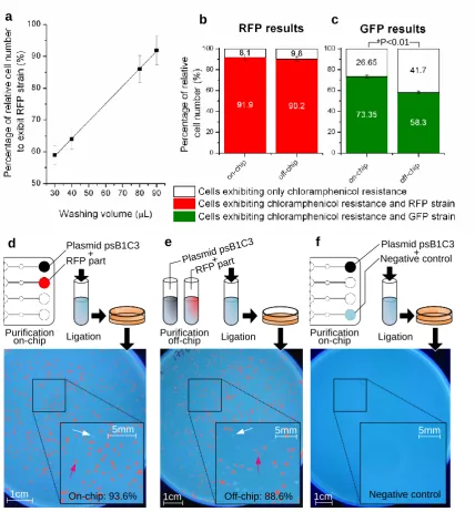
3.4. Biological validation with parallel genome segment purification
Methods section), adapted for a microfluidic manipulation and used as the validation of the
integrated platform and associated chip presented.
3.4.1. Influence of wash cycles on part purification
Up to 3 genome segments (backbone plasmid, RFP and GFP parts) parallel purification was
demonstrated in the chip design outlined in section2 and Figure 2. For all parts, the volume of
washing buffer was found to be critical for purification performance. Fig.5.A shows the
purification improvement for washing volumes of 30 µL, 40 µL, 80 µL and 90 µL. The
lowest purity of 57% is achieved for the smallest washing buffer volume (30 µL), while a
purity above 90% is achieved for a volume of 90 µL. The purity linearly improves with the
amount of washing buffer. These figures show that washing steps to remove unwanted oligos
are the most critical steps in the on-chip protocol. Although it was found that larger washing
volumes increase the purity of the final product, different optimisation strategies could reduce
the volume actually needed to perform the washing; for example a reduction of the reaction
chamber volume could enhance the mixing process. Furthermore, an improvement in purity
was also noted with a change in the magnetic mixing regime, which might even further
enhance the washing of unwanted oligos (data not shown). The whole single purification step
took about 35 minutes, for all three genome segments to be purified in parallel.
Comparatively, the duration of the “manual” bench control was longer as the magnetic
actuation and elution steps have to be done serially for each tube.
3.4.2. Cross-contamination control
In the purification chip (Figures 1 and 2), each parallel channels are physically separated
from one another. To study the possibility of cross-contamination via an exchange of
solutions in the laminated layers or between wells, the fourth channel in the chip was always
filed with DI water (negative control). This channel was actuated in the same way as the
ligation reaction with the content of the output well as insert and purified backbone plasmid
as vector was carried out. It was expected that if contamination from adjacent wells
containing GFP and RFP inserts was occurring, then colonies showing modified strain would
grow on the control plate. Across all experiments carried out in this study, no contamination
was found. A plate corresponding to this negative control is shown in Fig.5.f. These results
indicate that no contamination occurs via the laminated layers or input wells.
3.4.3. Validation of the platform for parallel genome segments purification
DNA purification using magnetic beads has been demonstrated in microfluidic chips by
several groups (Karle et al. 2009; Oblath et al. 2013) in the context of DNA extraction from
cells and prior to PCR. However, no parallel purification of several long genome segments
(several kb) has been yet demonstrated in the context of synthetic biology. Here the challenge
is not to extract DNA from a sample but to remove undesired oligos from a genome sequence
mixture before gene synthesis. Undesired or unbound oligos otherwise threaten the
performance of the final assembly or synthesis if not removed (Carr and Church 2009). While
in the first case (DNA extraction in prior to PCR), the performance of the chip will be
assessed by directly measuring the amount of DNA extracted, in the later case the
performance of the system is measured by transforming cells using the purified DNA to
verify if all unwanted oligos have been removed from the initial mixture. Transformation results with RFP plasmids. The performances of the on-chip protocol are compared to the bench-top protocol for washing volumes of 90 µL. Both on-chip and bench-top control were
performed on the same day and with the same reagents. The final assembled products were
also transformed and cells plated on the same day. As shown in Figure 5.b, the on-chip
protocol has comparable performance compared with the conventional protocol with
respective ratio of cells with the correct phenotype: 91.85% (CV=2.47, N=2) and 90.15%
results show that the on-chip results are comparable to the bench control but may not be
statistically different. Figures 5.d and 5.e display the transformed cells on agar plates. The
associated negative control described earlier is shown in Figure 5f. In Figure 5.d the cells
have been transformed with the recombinant DNA parts after a double purification on-chip,
while in 5e, the cells are transformed using the off-chip derived products. The yield is on the
same order of magnitude in both plates. Transformation results with GFP plasmids. In the transformations with the recombinant DNA containing the GFP insert the on-chip
purification was found to be substantially more efficient by approximately 20% than the
bench-top off-chip experiments (on-chip ratio of correct phenotypes: 75.4%, off-chip ratio of
correct phenotypes: 58.3%, p-value = 0.007) (Figure 5.c). The two repeats of the on-chip and
off-chip results were found to within the same range with a small coefficient of variation (on
chip: CV=1.3, N=2; off-chip CV=1.3, N=2) indicating that this process might have a good
overall repeatability. Generally, the purity of colonies with GFP parts was however lower
than the purity of colonies with RFP parts (on average 16.5% lower for the on-chip process
and 31.9% lower for the off-chip process). These differences with the RFP purification tests
could be explained by a difference in transformation efficiencies of the competent cells used.
However, even in the absence of a statistical analysis, these results indicate that the on-chip
protocol could potentially outperform the conventional bench protocol. Further research is
needed to increase the present data set and generalise these conclusions. Channel-to-channel reproducibility. On a chip, every channel and associated reaction chamber are expected to perform the same. In one experiment using 90 µL wash volumes, two RFP parts purifications
were performed side-by-side in the middle channels. A variation of purity inferior to 2.7%
was found between the two channels (which respectively led to 93.6 and 90.9% of correct
phenotypes, bench control: 88.6%), indicating that good reproducibility of the process may
V. Conclusions
In conclusion, the microfluidic purification is identical or performs better (by up to 20%) than
the conventional equivalent which validates the use of an automated microfluidic device and
protocol for the parallel purification of genome segments for synthetic biology applications.
The decoupling concept behind the platform permits the use of low-cost polymeric chips
while allowing the process of complex biological protocols in an automated fashion.
Although research and commercial solutions have been developed to alleviate the issue of
sample introduction in the chip, including the Fluidigm chip kits and the CARD device from
Rheonix, the system presented in this article is readily and fully compatible with existing
liquid handling workstations to enable automated genome purification and assembly at a
large range of volumes (~ 0.5 µL–1 mL). Temperature and magnetic controls have been
integrated in the permanent platform and demonstrated with a simple chip design. The
disposable chip is simply clamped in less than a few seconds onto the platform and does not
require the plugging of any tubing. In this paper, we have demonstrated an application of this
platform through the parallel purification of genome segments. Purification of up to four
pre-assembled segments in parallel was achieved on-chip, although the throughput could easily
be quadrupled, as the chip format allows up to 16 channels with the same features.
Additionally, the throughput could even be higher if the dimensions of the wells (and
scaled-down valves and other features) were spaced out with the standard 384-well plate pitch.
Purification was demonstrated on-chip with up to 20% better purity compared to the
bench-top equivalent protocol. DNA binding to the microfluidic material (PMMA, polymer
membrane) should be taken into account and might need to be characterized in the future.
The decoupled platform and its different actuation mechanisms are highly versatile many
applications could benefit from this automated, small scale device including cell culture and
18
Acknowledgements
Funding from ITI/Scottish Enterprise for the Genome Segment Assembly programme is
acknowledged. We thank Gingko Bioworks Inc. for supplying the biological reagents and
DNA parts. The Advanced Manufacturing Centre at Heriot-Watt is acknowledged for the
manufacturing of the mechanical parts. The thermochromic ink was provided by the company
Chromazone Ltd.
Footnote
Conflict of interest statement: WS and FA are founders and shareholders of Accufluidics Ltd.
MKK, FA and WS have applied for several patents relating to the method described in this
study. Other authors declare no conflict of interest.
References
Balagadde FK, You LC, Hansen CL, Arnold FH, Quake SR. 2005. Long-term monitoring of
bacteria undergoing programmed population control in a microchemostat. Science
309(5731):137-140.
Becker H. 2010. Mind the gap! Lab Chip 10(3):271-273.
Boehm CR, Freemont PS, Ces O. 2013. Design of a prototype flow microreactor for synthetic
biology in vitro. Lab on a Chip 13(17):3426-3432.
Carr PA, Church GM. 2009. Genome engineering. Nat Biotechnol 27(12):1151-1162.
Che A. 2008. http://www.cambridgeigem.org/asGenBank.php?part=pSB1C3 pCambridge
iGEM
Che A, Knight T, Canton B, Kelly J, Shetty R; Iti Scotland Limited, assignee. 2012. Method
For Assembly Of Polynucleic Acid Sequences. US.
Colin VL, Rodriguez A, Cristobal HA. 2011. The role of synthetic biology in the design of
Cortese B, Mowlem MC, Morgan H. 2011. Characterisation of an irreversible bonding
process for COC–COC and COC–PDMS–COC sandwich structures and application
to microvalves. Sensors Actuat B-Chem 160(1):1473-1480.
Fu AF, Chou H, Spence C, Arnold FH, Quake SR. 2002. An integrated Microfabricated Cell
Sorter. Anal Chem 74:2451-2457.
Gomez-Sjoeberg R, Leyrat AA, Pirone DM, Chen CS, Quake SR. 2007. Versatile, fully
automated, microfluidic cell culture system. Anal Chem 79(22):8557-8563.
Grover WH, von Muhlen MG, Manalis SR. 2008. Teflon films for chemically-inert
microfluidic valves and pumps. Lab Chip 8(6):913-918.
Gulati S, Rouilly V, Niu X, Chappell J, Kitney RI, Edel JB, Freemont PS, deMello AJ. 2009.
Opportunities for microfluidic technologies in synthetic biology. J. R. Soc. Interface.
Hong JW, Quake SR. 2003. Integrated nanoliter systems. Nat Biotechnol 21(10):1179-1183.
Karle M, Miwa J, Roth G, Zengerle R, Von Stetten F. A Novel Microfluidic Platform for
Continuous DNA Extraction and Purification using Laminar Flow Magnetophoresis;
2009 25-29 Jan. 2009. p 276-279.
Kim J, Surapaneni R, Gale BK. 2009. Rapid prototyping of microfluidic systems using a
PDMS/polymer tape composite. Lab Chip 9(9):1290-3.
Ko YJ, Maeng JH, Ahn Y, Hwang SY. 2011. DNA ligation using a disposable microfluidic
device combined with a micromixer and microchannel reactor. Sensor Actuat
B-Chem 157(2):735-741.
Kong DS, Carr PA, Chen L, Zhang S, Jacobson JM. 2007. Parallel gene synthesis in a
microfluidic device. Nucleic Acids Res 35(8).
Lee C-C, Snyder TM, Quake SR. 2010. A microfluidic oligonucleotide synthesizer. Nucleic
Lee CC, Sui GD, Elizarov A, Shu CYJ, Shin YS, Dooley AN, Huang J, Daridon A, Wyatt P,
Stout D and others. 2005. Multistep synthesis of a radiolabeled imaging probe using
integrated microfluidics. Science 310(5755):1793-1796.
Lin H-C, Liu Y-J, Yao D-J. 2010. Core-Shell Droplets for Parallel DNA Ligation of an
Ultra-micro Volume Using an EWOD Microfluidic System. Jala 15(3):210-215.
Nath P, Fung D, Kunde YA, Zeytun A, Branch B, Goddard G. 2010. Rapid prototyping of
robust and versatile microfluidic components using adhesive transfer tapes. Lab Chip
10(17):2286-2291.
Oblath EA, Henley WH, Alarie JP, Ramsey JM. 2013. A microfluidic chip integrating DNA
extraction and real-time PCR for the detection of bacteria in saliva. Lab on a Chip
13(7):1325-1332.
Ogilvie IR, Sieben VJ, Cortese B, Mowlem MC, Morgan H. 2011. Chemically resistant
microfluidic valves from Viton(R) membranes bonded to COC and PMMA. Lab Chip
11(14):2455-9.
Richmond KE, Li MH, Rodesch MJ, Patel M, Lowe AM, Kim C, Chu LL, Venkataramaian
N, Flickinger SF, Kaysen J and others. 2004. Amplification and assembly of
chip-eluted DNA (AACED): a method for high-throughput gene synthesis. Nucleic Acids
Res 32(17):5011-5018.
Shaikh KA, Ryu KS, Goluch ED, Nam J-M, Liu J, Thaxton CS, Chiesl TN, Barron AE, Lu
Y, Mirkin CA and others. 2005. A modular microfluidic architecture for integrated
biochemical analysis. Proceedings of the National Academy of Sciences of the United
States of America 102(28):9745-9750.
Skafte-Pedersen P, Sip CG, Folch A, Dufva M. 2013. Modular microfluidic systems using
reversibly attached PDMS fluid control modules. Journal of Micromechanics and
Smolke CD, Silver PA. 2011. Informing Biological Design by Integration of Systems and
Synthetic Biology. Cell 144(6):855-859.
Sollier E, Murray C, Maoddi P, Di Carlo D. 2011. Rapid prototyping polymers for
microfluidic devices and high pressure injections. Lab Chip 11(22):3752-65.
Squires TM, Quake SR. 2005. Microfluidics: Fluid physics at the nanoliter scale. Rev. Mod.
Phys. 77(3):977-1026.
Szita N, Polizzi K, Jaccard N, Baganz F. 2010. Microfluidic approaches for systems and
synthetic biology. Curr. Opin. Biotech. 21(4):517-523.
Tan HY, Loke WK, Nguyen N-T. 2010. A reliable method for bonding polydimethylsiloxane
(PDMS) to polymethylmethacrylate (PMMA) and its application in micropumps.
Sensor Actuat B-Chem 151(1):133-139.
Tian JD, Gong H, Sheng NJ, Zhou XC, Gulari E, Gao XL, Church G. 2004. Accurate
multiplex gene synthesis from programmable DNA microchips. Nature
432(7020):1050-1054.
Unger MA, Chou HP, Thorsen T, Scherer A, Quake SR. 2000. Monolithic microfabricated
valves and pumps by multilayer soft lithography. Science 288(5463):113-116.
Vinuselvi P, Park S, Kim M, Park JM, Kim T, Lee SK. 2011. Microfluidic Technologies for
Synthetic Biology. Int. J. Mol. Sci. 12(6):3576-3593.
Webb DP, Knauf B, Liu C, Hutt D, Conway P. 2009. Productionisation issues for
commercialisation of microfluidic based devices. Sens. Rev. 29(4):349-354.
Wu AR, Hiatt JB, Lu R, Attema JL, Lobo NA, Weissman IL, Clarke MF, Quake SR. 2009a.
Automated microfluidic chromatin immunoprecipitation from 2,000 cells. Lab Chip
Wu AR, Hiatt JB, Lu R, Attema JL, Lobo NA, Weissman IL, Clarke MF, Quake SR. 2009b.
Automated microfluidic chromatin immunoprecipitation from 2,000 cells. Lab Chip
9(10):1365-1370.
Xia YN, Whitesides GM. 1998. Soft lithography. Angew Chem Int Ed 37(5):551-575.
Zhang W, Lin S, Wang C, Hu J, Li C, Zhuang Z, Zhou Y, Mathies RA, Yang CJ. 2009.
PMMA/PDMS valves and pumps for disposable microfluidics. Lab Chip
9(21):3088-3094.
Zhou XC, Cai SY, Hong AL, You QM, Yu PL, Sheng NJ, Srivannavit O, Muranjan S,
Rouillard JM, Xia YM and others. 2004. Microfluidic PicoArray synthesis of
oligodeoxynucleotides and simultaneous assembling of multiple DNA sequences.
Nucleic Acids Res 32(18):5409-5417.
List of Figures
Fig.1: Clamp n’Play modular platform concept. Schematic diagrams of the decoupling
strategy with a bird-eye view of the disposable microfluidic chip and pneumatic integrated
platform. The disposable chip is clamped into position on the control platform. After use, the
chip is unclamped and disposed as biological waste. The circled letters describe: A) the disposable and detachable PMMA chip (total thickness, approximately 4.5 mm). For chip
fabrication and details of the various layers, check supplementary material B) the elastomer membrane (approximately 50µm thickness) which seals the PMMA chip, isolates the chip
from the platform while allowing fluid actuation via the platform C) the underlying permanent control platform with actuators (pneumatic, thermal and mechanical). The active
contamination. The circled numbers describe: 1) An input well (total volume approx 50 µL)
2) A valve element (total volume approx 0.2 µL) 3) A pumping chamber (total volume approx 1 µL). The pump itself consists of two valve elements and a pumping chamber 4) A reaction chamber (total volume 5-20 µL) 5) An output well (identical to the input well) 6)
Compressed air access for the opening and closure of the pneumatic actuators (valves and
pumping chamber). X represents a closed valve, and O, an opened valve. The pumping
pattern was XOO, XXO, OXO, OXX, OOX, XOX. By default, the valves and pumping
chambers were kept closed. Inserts show (i) the temperature control under the reaction chamber. The use of a thermochromic ink with a temperature switch of 47°C allows the
visualisation of the temperature variation. Here, a Peltier element is set at 49°C and flow is
actuated with a 4 Hz frequency, (ii) the magnetic actuation for mixing and target capture in the reaction chamber. 10 µm streptavidin magnetic beads are trapped by the magnet and can
be moved around in a pack and (iii) a disposable chip made of out PMMA and filled with red dye.
Figure 2: (a) Biological protocol from genome segment pre-assembly to transformation into competent cells. The parts are pre-assembled off-chip using overhangs (data not shown, refer
to (Che et al. 2012) for a full description of the assembly process). The purification of four
pre-assembled parts is performed in parallel on the integrated platform on a disposable chip.
After the double-purification, a ligation reaction combines RFP or GFP inserts with plasmid
PsB1C3 and the recombinant DNA is transformed in competent cells. The cells are plated on
Agar plates and incubated for 12h, after which the colonies are observed UV light and
counted using an imaging software. The first three steps with an asterisk are repeated for all
the parts: RFP, GFP and the plasmid psB1C3. The purification of all parts is performed in
were first washed with DI water to remove any unwanted particles after the fabrication. All
the valves were closed, the magnet on the robotic arm was in place above the chamber and
20µL of streptavidin-coated magnetic beads were loaded into the wells by manual pipetting.
The flow (4Hz) was activated until the input well was empty and the beads had travelled to
the reaction chambers via parallel pneumatic actuation of the pumps. The output wells were
regularly emptied with a pipette. The flow direction is indicated by an arrow. The magnet is
placed above the reaction chambers to capture the beads. Stage II: Oligo solution and binding buffer loading and mixing 1µL of oligos solution was pipetted into all wells as well as an additional 10µL of binding buffer was pipetted into all the wells. These solutions were
pumped into the reaction chamber; once the wells were emptied the actuation was stopped.
The valves at the entrance and exit of the reaction chamber were closed and the magnet was
moved linearly through robotic or manual control for about 30 s. The magnet was then moved
away from the chamber and the mixture was incubated for 10 minutes at 20ºC. After
incubation, the magnet was placed against the reaction chamber. Stage III: Ligation mix loading, mixing and incubation. Next, 1µL of NaCl solution and 10µL of ligation mix are introduced in the same way and the magnet is moved to allow the mixing of the reagents. The
unbound oligos are washed away with a washing buffer (not shown, for volumes cf results).
Stage IV: Elution 15µL of elution buffer was pipetted in each of the wells. About 5 µL of buffer was pumped into the reaction chamber and mixed gently using the magnet. The output
wells were emptied. The heater was set to 65ºC and allowed to reach this temperature at
which point the reminder of the input wells was pumped through. 10 µL of elution solution
was pipetted from each output well and stored into labelled tubes for off-chip assembly.
The star on each curve is a data point that marks the optimal frequency on each curve. (b)
Performance variations of a pump at operational frequency of 1Hz. The error bars denote the
Standard Deviation (n=5), of respectively 0.55, corresponding to a Relative Standard
Variations (RSD) of 1.1%. The red line denotes the average across the control group
Figure 4:Magnetic and thermal actuation (a) Photographs of the magnetic capture inside the chamber (a-i) the chamber filled with water (a-ii) the chamber filled with beads (a-iii) The
chamber with the magnet applied and the beads aggregating. (b) Photographs of the chamber
above the Peltier device, filled with thermochromic ink (Tt=47°C 2°C). (b-i) Before the
Peltier element is activated (b-ii) 10 s after the Peltier element is activated, the control
temperature is 49°C, no flow (b-iii) Under a driving frequency of 4 Hz. For a video of (b-iii)
refer to online supplementary material section.
Figure 5: Validation of an integrated platform for on-chip purification of DNA segments (a)
Influence of the washing volumes on the purity in the RFP plasmid transformation. The
highest washing volume (90 µL) gives the best result in terms of performance after assembly
(93.6%) (b) Comparison of on-chip (93.6%, CV=2.47, N=2) and off-chip purity (88.6%, CV=2.19, N=2) after the assembly of the RFP parts in the plasmid vector. The difference
between the two sets of data is not statistically significant with p-value = 0.7 (>0.01) (c)
Comparison of on-chip (75.3%) and off-chip purity (58.3%) after the assembly of the GFP
parts and plasmid vector. The difference between the two data sets is statically significant
with a p-value=0.0075<0.005 (Student t-test, the data is representative of 2 independent
experiments) (d) Plating results after transformation of competent E-Coli cells with recombinant DNA containing plasmid vector and RFP inserts purified on-chip. To facilitate
open-source illustration software (ImageJ). The red arrows points on a colony with the
modified strain. A white arrow points out on a colony with an un-modified strain (e) Plating
results after transformation of competent E-Coli cells with recombinant DNA containing
plasmid vector and RFP inserts purified off-chip (f) No cells are present in the negative water
control, demonstrating the absence of cross-contamination between the parallel channels and
[image:26.595.92.513.297.535.2]thereby the absence of leakage which could occurred through delamination in the chip
Figure 1
Magnet mounted on robotic arm Manual or robotic well loading Standard 4.5mm 96-well plate pitch for fluid handling robot compatibility 5mm Flow Peltier element Streptavidin magnetic beads Assembled detachable and disposable chip
Temperature control (0-95ºC)
Thermochromic ink (switch Tº=47ºC±1ºC) Tº>47ºC Tº<47ºC Standard 4.5mm 96-well plate pitch 1mm
1-10µm magnetic beads actuation for trapping and
mixing purpose Flow Magnetic actuation
1mm Overview of the microfluidic pneumatic platform and actuators
A
B
C
1
2 3 4
Figure 2
Colony counting after 12h incubation
Purification step 1
Oligos and binding buffer
Streptavidin coated magnetic beads
NaCl and ligation mix (step 1) or elution product (step 2) Elution buffer Oligos and pre-assembly mix Elution product Heating Magnetic mixing b + GFP par t RFP par t Neg ativ
e co ntro
l
a
b
Pre-assembly of DNA parts
Ligation Purification step 2
Transformation Cell culture
Competent E.Coli cells+ waste
Streptavidin coated magnetic particle and purification oligo
F lo w d ir e c ti o n P u m p V a lv e R e a c ti o n c h a m b e r In p u t re s e rv o ir O u tp u t re s e rv o ir
Manual or auto-mated pipetting
LB Agar culture plate with chlo-ramphenicol, 12 hours incubation
at 37ºC waste Parts A (e.g. RFP) Part linker (PL) oligos Assembled (recombinant) DNA elution elution Transformed cells Transformed cells Purified product
Stage I Stage II Stage III Stage IV
Pla sm
id p sB1C 3 On-chip operation Off-chip operation Plasmid psB1C3
Parallel microfluidic purification step 1 or 2 Colony carrying
chloramphe-nicol resistance
Colony carrying chloramphe-nicol resistance and exhibiting RFP strain
Figure 3
Figure 4
a-i
a-iii
a-ii
b-i
[image:28.595.123.474.120.691.2]Figure 5
RFP part
RFP part
Plasmid psB1C3
On-chip: 93.6%
d
1cm
5mm
Off-chip: 88.6%
e
1cm
5mm
Negative control
f
1cm
5mm
Negative control Plasmid psB1C3
Plasmid psB1C3
Purification
on-chip Ligation Purification off-chip Ligation Purification on-chip Ligation
a b c
+
+ +