Real-Time Teleprotection Testing using IP/MPLS over xDSL
May 2013
Dr Steven Blair, Dr Campbell Booth University of Strathclyde
Abstract
Teleprotection for power systems is safety-critical and has demanding requirements for bandwidth, low latency, and low jitter. Traditionally, time-division multiplexing (TDM) using SONET/SDH circuits has been used to provide this quality of service. Modern packet-based networks offer several advantages, such as improved flexibility and greater bandwidth efficiency. With IP/MPLS, packet-based networks can cater for teleprotection functionality. This report demonstrates the potential for commercially-available IP/MPLS hardware to provide teleprotection functionality over two DSL technologies, VDSL and SHDSL. A real-time hardware in the loop environment has been developed to test these schemes under a variety of scenarios, which are indicative of real-world conditions. Commercially-available protection relays were used to implement C37.94-based communications, and the stability of the protection functions were monitored closely during the testing.
The results highlight the maximum DSL line distance and the remaining bandwidth (after provisioning for the teleprotection) which can be achieved, whilst observing a 6 ms propagation delay restriction.
VDSL is only suitable for links up to approximately 1.4 km, although it can deliver relatively high bandwidth of 4-19 Mbps, depending on the line distance.
SHDSL can support up to 4-5 km per span. Distances of approximately 4.3 km offer a good compromise of distance, delay, and remaining bandwidth. Using two serially-connected SHDSL spans is beneficial: it can support either longer distances, or provide greater spare bandwidth.
Contents
1 Introduction ... 4
2 Motivation for Using IP/MPLS for Teleprotection ... 5
3 Hardware in the Loop Simulation ... 6
3.1 Overview ... 6
3.2 Laboratory Equipment ... 7
3.3 C37.94-Based Differential Protection Scheme ... 8
3.4 IP/MPLS Configuration ... 10
4 Testing Scenarios... 11
4.1 Controllable Parameters ... 11
4.2 Baseline Propagation Delay ... 11
4.3 Baseline VDSL and SHDSL Bandwidth ... 12
4.4 DSL Configurations ... 13
5 Results ... 14
5.1 Single-Span ... 14
5.1.1 VDSL ... 14
5.1.2 SHDSL... 14
5.2 Dual-Span ... 14
5.2.1 VDSL ... 14
5.2.2 SHDSL... 15
6 Summary and Conclusions ... 16
Glossary
CAPEX Capital Expenditure
CPU Central Processing Unit
CT Current Transformer
DSL Digital Subscriber Line
GOOSE Generic Object Oriented Substation Event
IP Internet Protocol
kbps Kilobits per second
LAN Local Area Network
Mbps Megabits per second
MPLS Multiprotocol Label Switching
OPEX Operational Expenditure
PDH Plesiochronous Digital Hierarchy
PWE3 Pseudo Wire Emulation Edge-to-Edge
RoHS Restriction of Hazardous Substances Directive
RTDS Real-Time Digital Simulator
SAR Service Aggregation Router
SAToP Structure-Agnostic Transport
SDH Synchronous Digital Hierarchy
SHDSL Single-pair High-speed Digital Subscriber Line
SONET Synchronous Optical Networking
TDM Time-Division Multiplexing
VDSL Very-high-bit-rate Digital Subscriber Line
VLAN Virtual Local Area Network
VT Voltage Transformer
1 Introduction
IP/MPLS has many compelling applications for power system communications. This report describes the use of IP/MPLS routers for providing current differential protection, a type of (and sometimes referred to as) teleprotection, over one or more xDSL links. Teleprotection has very stringent requirements relating to bandwidth and latency. For the application described in this report, a strict 6 ms maximum propagation delay limit applies. It is also desirable to maximise the remaining bandwidth – after provisioning for the teleprotection service – for other applications, such as system monitoring and control.
2 Motivation for Using IP/MPLS for Teleprotection
The overall motivation for using IP/MPLS for teleprotection is to improve efficiency in multiple areas:
1. A teleprotection “c-pipe” creates the effect of a dedicated time-division multiplexing (TDM) link, using the Pseudo Wire Emulation Edge-to-Edge (PWE3) architecture [1]. An emulated TDM pseudo wire over IP/MPLS does not suffer from the potential bandwidth inefficiency which can be associated with TDM; IP/MPLS only uses the bandwidth when data has to be sent, contrary to TDM where a time channel is reserved at all times.
2. IP/MPLS offers significantly better operational flexibility than TDM technology: provisioning a new teleprotection service or modifying/removing an existing one is a straightforward task in an IP/MPLS network. In a TDM environment, it is more cumbersome due to the static assignment of the time slots.
3. Converging multiple networks into a single unified IP/MPLS network, rather than operating separate networks for teleprotection and for other functions, results in a lower Total Cost of Ownership. Both CAPEX and OPEX are reduced:
a. The total CAPEX for traditionally separated SDH, PDH, and IP equipment (and LAN switches) is higher than a single IP/MPLS router. Tailored hardware interfaces for the IP/MPLS equipment ensure that legacy substation equipment does not need to be replaced, but can take advantage of an IP/MPLS network.
b. From an OPEX perspective, a single IP/MPLS network reduces the diversity in management software, staff training requirements, physical footprint (i.e., rack space usage), cooling requirements (e.g., extended temperature range), and spending on energy (i.e., IP/MPLS devices are more energy-efficient).
3 Hardware in the Loop Simulation
3.1 Overview
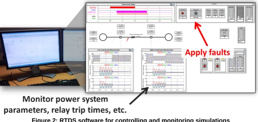
[image:7.595.110.488.207.375.2]A hardware in the loop environment is a powerful technique for testing real devices under many possible scenarios [2], [3]. A Real-Time Digital Simulator (RTDS) [4] has been used to simulate a power system. As shown in Figure 1, an RTDS can be interfaced with real equipment, such as protection relays, in a closed-loop configuration. Figure 2 illustrates the software used to control and monitor real-time simulations within the RTDS.
Figure 1: Hardware in the loop protection relay testing
Figure 2: RTDS software for controlling and monitoring simulations
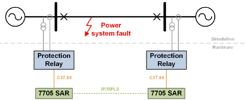
[image:7.595.86.503.420.618.2]Figure 3: Differential Protection Testing Arrangement
3.2 Laboratory Equipment
Figure 4, Figure 5, Figure 6, and Figure 7 show the full laboratory arrangement. The following equipment has been used in this investigation:
Two Alstom P545 differential protection relays, with C37.94 optical interfaces.
Two Alcatel-Lucent 7705 Service Aggregation Routers (SARs), with Voice and Teleprotection cards. The 7705 SARs are thereby designed to connect directly to the C37.94 optical connectors on the protection relays.
Four Nokia Siemens FlexiNT22 SHDSL modems. Four RuggedCom RS930L VDSL modems. Spirent VDSL and SHDSL line emulators.
[image:8.595.73.532.461.642.2] RTDS, and two injection amplifiers which are used to supply the protection relays with currents and voltages amplified from the +/-10 V outputs of the RTDS.
Figure 6: RTDS and 7705 SARs in laboratory Figure 7: RTDS and 7705 SARs (with equipment annotated)
3.3 C37.94-Based Differential Protection Scheme
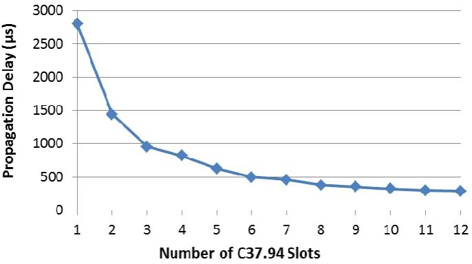
C37.94 is a standard for transporting data using optical links. It uses TDM, and thereby guarantees a particular bandwidth and a fixed latency. C37.94 provides up to 12 “slots”, each providing 64 kbps of usable end-to-end bandwidth. A time division of 125 µs (8 kHz) is used, such that one byte of data is delivered, per slot, every 125 µs. Timing is critical for differential protection applications, and TDM is therefore attractive in terms of ensuring deterministic and accurate timing.
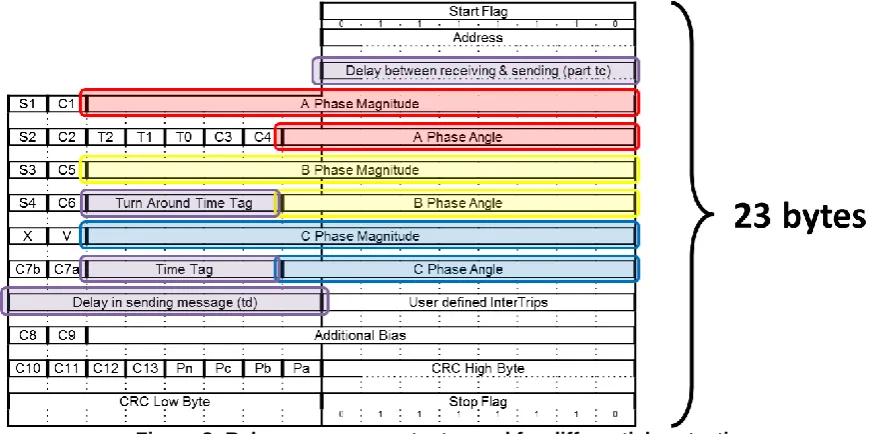
[image:9.595.75.512.470.687.2]The Alstom P545 protection relays use a 23 byte message for delivering differential protection functionality (i.e., primarily for transferring measurement and other data from one relay to the other(s) in the scheme), as depicted in Figure 8. The data fields used for determining the propagation delay between the two relays are highlighted in purple.
Figure 8: Relay message contents used for differential protection
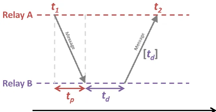
the propagation delay using Equation 1. The same process occurs simultaneously for Relay B.
Figure 9: Simplified propagation delay calculation process
=
−
−
Equation 1: Propagation delay time calculation
Using one C37.94 slot, the propagation delay in this case is approximately 2.88 ms:
=
𝟑 𝐛𝐲𝐭𝐞𝐬 × 𝟖
𝟔𝟒 𝐤𝐛𝐩𝐬
= . 𝟖𝟖 𝐦𝐬
Similarly, using all 12 slots leads to a propagation delay of approximately 240 µs:
=
𝟑 𝐛𝐲𝐭𝐞𝐬 × 𝟖
× 𝟔𝟒 𝐤𝐛𝐩𝐬
= 𝟒𝟎 𝛍𝐬
3.4 IP/MPLS Configuration
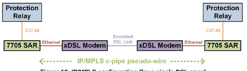
[image:11.595.98.498.148.263.2]The two 7705 SARs have been used to establish a “c-pipe” pseudo-wire within the IP/MPLS network. This emulates a point-to-point TDM connection between the two routers, assuming that the DSL link provides sufficient bandwidth.
Figure 10: IP/MPLS configuration (for a single DSL span)
At each 7705 SAR, one or more outgoing C37.94 frames are grouped into a payload. The number of frames that can be stored in an IP/MPLS packet is tuneable. An overhead of 30 bytes, shown in Figure 11, must be added to each payload. The resulting Ethernet frame is passed over the xDSL connection, and is depacketised by the receiving 7705 SAR. A jitter buffer is used to ensure that the C37.94 frames are “played-out” to the receiving protection relay at a constant rate, thereby neutralising possible jitter effects in the IP/MPLS network.
[image:11.595.110.485.384.439.2]4 Testing Scenarios
4.1 Controllable Parameters
Table 1 summarises the controllable parameters for the testing. Due to the large number of combinations, a representative selection of values has been tested.
Item Typical values Comments C37.94
slot size
1 to 12 slots Defines the end-to-end usable bandwidth: 64 to 768 kbps, respectively. The underlying communications medium (in this case, xDSL) must provide this bandwidth, plus the overhead.
Frames per payload
2 to 12 frames The number of C37.94 frames per payload defines the
packetisation delay. E.g., for 4 frames per payload, the packetisation delay is 4 x 125 µs = 500 µs.
In this investigation, a maximum value of 12 frames per payload has been used, with an associated delay of 1.5 ms.
MPLS payload size
2 to 144 bytes This value is not varied directly, but is dictated by the slot size and the desired number of frames per MPLS payload, because an integer multiple of frames should be included in each MPLS payload. E.g., for a slot size of 8, at 4 frames per payload, the payload size should be 8 x 4 = 32 bytes.
Larger payload sizes lead to increased latency, but make more efficient use of the available bandwidth.
Smaller payload sizes lead to an increase in the rate of Ethernet frames generated, which increases the load on the DSL modems.
Jitter buffer size
1 to 4 ms The jitter buffer is necessary for ensuring that a constant stream of data is provided to each protection relay (such that the protection algorithm remains stable), regardless of variations in actual delay.
The jitter buffer is “played-out” when half full, so it adds a fixed delay of half the buffer size.
Copper line length
0 to 2.5 km (VDSL) 0 to 6.7 km (SHDSL)
[image:12.595.68.528.156.559.2]The Spirent devices used in this investigation emulate copper wires with a cross-sectional area of 0.4 mm2, whereas the actual copper lines are 0.9 mm2. This means that the results in this report will tend to underestimate the DSL performance.
Table 1: Summary of controllable parameters
4.2 Baseline Propagation Delay
[image:12.595.176.415.674.714.2]Figure 13: Propagation delay results
4.3 Baseline VDSL and SHDSL Bandwidth
Figure 14 compares the bandwidth profiles for the VDSL and SHDSL modems. The bandwidth is recorded from the management interface for each set of DSL modems and the values are symmetrical, i.e., the “up” and “down” values are the same. As would be expected, VDSL offers much higher bandwidth, but is severely restricted by distance. SHDSL offers generally lower but more consistent bandwidth values, but the bandwidth drops off for connection distances between 2.5 km and 5 km.
[image:13.595.85.511.521.743.2]It has been observed that accessing the management interface for either DSL modem type would interfere with the teleprotection c-pipe for certain MPLS payload sizes, resulting in protection instability. This may be caused by a flaw in the modem configuration, or by a design flaw resulting in excessive CPU load and cessation of the primary function of the modem. The modems typically take several minutes to “re-train” if the DSL link is temporarily lost.
4.4 DSL Configurations
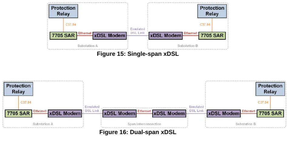
[image:14.595.70.544.174.408.2]Each DSL technology (VDSL and SHDSL) has been tested in both single-span and dual-span configurations. These are illustrated in Figure 15 and Figure 16 respectively. Dual-dual-span configurations allow greater total distances to be achieved, but the additional DSL modems at the “middle” of the link must be powered which may be a significant practical disadvantage.
[image:14.595.148.452.176.260.2]Figure 15: Single-span xDSL
5 Results
This section highlights the key results from the testing. Note that the values for the bandwidth efficiency, bandwidth used, and remaining bandwidth (after provisioning the teleprotection service) are based on the MPLS payload and overhead sizes – and therefore are estimates.
In each case, the protection relays remained stable, i.e., the protection algorithm did not issue a communications error, and the relays would trip correctly for simulated faults, with a total trip time of 20-30 ms (ignoring the circuit breaker opening time), which presumably lies within the range of acceptable performance.
5.1 Single-Span
[image:15.595.67.532.310.430.2]5.1.1 VDSL
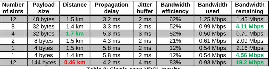
Table 2 presents the key results for single-span VDSL. The maximum distance which can be achieved reliably is approximately 1.7 km. In most cases, relatively high values of bandwidth remain for other applications.
Number of slots
Payload size
Distance Propagation delay Jitter buffer Bandwidth efficiency Bandwidth used Bandwidth remaining
12 48 bytes 1.5 km 3.2 ms 2 ms 62% 1.25 Mbps 1.45 Mbps
8 32 bytes 1.4 km 3.3 ms 2 ms 52% 0.99 Mbps 4.11 Mbps
4 32 bytes 1.7 km 5.3 ms 3 ms 52% 0.50 Mbps 0.70 Mbps
2 8 bytes 1.5 km 4.3 ms 2 ms 21% 0.61 Mbps 2.09 Mbps
1 4 bytes 1.5 km 5.8 ms 2 ms 12% 0.54 Mbps 2.16 Mbps
1 4 bytes 1.4 km 5.8 ms 2 ms 12% 0.54 Mbps 4.56 Mbps
12 144 bytes 0.46 km 4.2 ms 4 ms 83% 0.93 Mbps 19.2 Mbps
Table 2: Single-span VDSL results
5.1.2 SHDSL
As shown in Table 3, SHDSL can achieve significantly greater distances than VDSL, with a maximum stable value of 4.9 km. However, distances of approximately 4.3 km yield significantly higher bandwidth and this value may represent a more stable limit than the absolute limit of 4.9 km.
Number of slots
Payload size
Distance Propagation delay Jitter buffer Bandwidth efficiency Bandwidth used Bandwidth remaining
12 132 bytes 4.9 km 5.96 ms 3 ms 81% 0.94 Mbps 0.21 Mbps
8 64 bytes 4.9 km 5.5 ms 3 ms 68% 0.75 Mbps 0.40 Mbps
8 96 bytes 4.3 km 5.1 ms 4 ms 76% 0.67 Mbps 1.76 Mbps
4 32 bytes 4.9 km 5.5 ms 3 ms 52% 0.50 Mbps 0.66 Mbps
[image:15.595.71.530.527.622.2]2 16 bytes 4.3 km 4.9 ms 3 ms 35% 0.37 Mbps 2.06 Mbps
Table 3: Single-span SHDSL results
5.2 Dual-Span
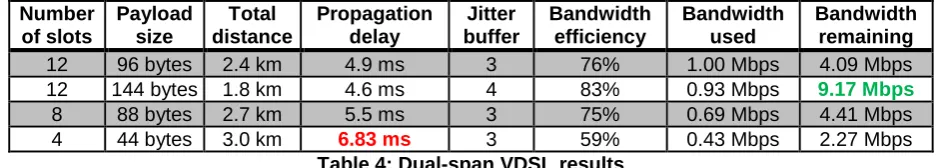
5.2.1 VDSL
Number of slots Payload size Total distance Propagation delay Jitter buffer Bandwidth efficiency Bandwidth used Bandwidth remaining
12 96 bytes 2.4 km 4.9 ms 3 76% 1.00 Mbps 4.09 Mbps
12 144 bytes 1.8 km 4.6 ms 4 83% 0.93 Mbps 9.17 Mbps
8 88 bytes 2.7 km 5.5 ms 3 75% 0.69 Mbps 4.41 Mbps
4 44 bytes 3.0 km 6.83 ms 3 59% 0.43 Mbps 2.27 Mbps
Table 4: Dual-span VDSL results
5.2.2 SHDSL
Table 5 and Table 6 illustrate the trade-off for dual-span SHDSL: either higher bandwidth can be achieved (Table 5) or greater total distance (Table 6). Table 6 illustrates examples of the maximum distances which can be achieved, but at the expense of relatively large propagation delays. Number of slots Payload size Total distance Propagation delay Jitter buffer Bandwidth efficiency Bandwidth used Bandwidth remaining
12 132 bytes 4.9 km 5.0 ms 3 ms 82% 0.94 Mbps 3.60 Mbps
8 88 bytes 4.9 km 5.0 ms 3 ms 75% 0.69 Mbps 3.86 Mbps
4 44 bytes 4.9 km 5.2 ms 4 ms 59% 0.43 Mbps 4.11 Mbps
Table 5: Dual-span SHDSL results (higher bandwidth)
Number of slots Payload size Total distance Propagation delay Jitter buffer Bandwidth efficiency Bandwidth used Bandwidth remaining
8 88 bytes 9.8 km 8.4 ms 3 ms 75% 0.69 Mbps 0.47 Mbps
8 88 bytes 10.0 km 9.7 ms 3 ms 75% 0.69 Mbps 0.35 Mbps
8 32 bytes (8.5 km) (4.5 ms) 2 ms 52% 0.99 Mbps 1.44 Mbps
Table 6: Dual-span SHDSL results (greater total distance)
[image:16.595.62.531.72.156.2]6 Summary and Conclusions
The results can be summarised as follows: MPLS as a technology, and as implemented by the Alcatel-Lucent 7705 SAR routers, has been proven to support teleprotection services with the associated stringent latency and jitter requirements.
VDSL is only suitable for short links, due to the relatively sharp decline in bandwidth with distance. It would be preferred over SHDSL for distances less than 1.4 km. SHDSL can support up to 4-5 km per span. Distances of approximately 4.3 km offer
a good compromise of distance, delay, and remaining bandwidth.
Dual-span SHDSL is beneficial: it can support either longer distances, or provide greater spare bandwidth. Further investigation is need to establish the cause of errors present for configurations which potentially offer total distances of up to 8.5 km with a propagation delay of 4.5 ms.
In general, the C37.94 slot size should be greater than 4 to help reduce latency. This requires at least 256 kbps of bandwidth.
The results illustrate that each DSL modem type favours certain payload sizes; other payload sizes (i.e., those not listed in Section 5) tend to result in higher propagation delays. The packetisation methods used by the DSL modems are unknown and further investigation is needed to fully analyse this phenomenon.
The DSL modem management interfaces are not reliably accessible without disrupting communications, and therefore the protection functionality must be interrupted if the modems need to be reconfigured.
There are inherent limitations to bandwidth, based on the available DSL technologies and the distances which are required.
Note that the results in this report have been obtained under laboratory conditions. Field trials are necessary to fully determine the actual xDSL performance. For example, impulse noise and crosstalk have not been emulated. The emulated DSL lines have a gauge of 0.4 mm2, rather than the actual rating of 0.9 mm2, so the results in this report will tend to underestimate the performance of the DSL modems.
7 References
[1] S. Bryant and P. Pate, “Pseudo Wire Emulation Edge-to-Edge (PWE3) Architecture,” RFC 3985, 2005. [Online]. Available: http://www.ietf.org/rfc/rfc3985.txt.
[2] S. Loddick, U. Mupambireyi, S. M. Blair, C. D. Booth, X. Li, A. J. Roscoe, K. Daffey, and J. Watson, “The Use of Real Time Digital Simulation and Hardware in the Loop to De-Risk Novel Control Algorithms,” in IEEE Electric Ship Technologies Symposium, 2011.
[3] F. Coffele, S. M. Blair, C. D. Booth, J. Kirkwood, and B. Fordyce, “Demonstration of Adaptive Overcurrent Protection Using IEC 61850 Communications,” in CIRED, 2013. [4] RTDS, “Real Time Power System Simulation - RTDS Technologies,” 2011. [Online].
Available: http://www.rtds.com. [Accessed: 08-Mar-2011].
[5] IEEE, “C37.94-2002 - IEEE Standard for N Times 64 Kilobit Per Second Optical Fiber Interfaces Between Teleprotection and Multiplexer Equipment,” 2003.
[6] P. Beaumont, F. Kawano, A. Kawarada, T. Kase, H. Sugiura, F. Lam, J. Hurd, P. Worthington, D. Richards, and P. Merriman, “Performance evaluation of current differential relays over a wide area network,” in 11th IET International Conference on Developments in Power Systems Protection (DPSP 2012), 2012, pp. 152–152.
[7] S. M. Blair, F. Coffele, C. D. Booth, and G. M. Burt, “An Open Platform for Rapid-Prototyping Protection and Control Schemes with IEC 61850,” IEEE Transactions on Power Delivery, vol. 28, no. 2, pp. 1103–1110, 2013.