1
Sun-Synchronous Highly Elliptical Orbits using Low-Thrust
Propulsion
Pamela Anderson 1 and Malcolm Macdonald2 University of Strathclyde, Glasgow, G1 1XJ, Scotland, E.U
Nomenclature
a = semi-major axis, kmCn,m = harmonic coefficients of Earth potential e = eccentricity
Fn = low-thrust normal perturbation scalar Fr = low-thrust radial perturbation scalar Ft = low-thrust transverse perturbation scalar i = inclination, deg
J2 = perturbation due to Earth’s oblateness N = normal perturbation acceleration, mm/s2 Pn,m = associated Legendre polynomials p = semi-parameter, km
R = radial perturbation acceleration, mm/s2 Re = mean radius of Earth, km
r = orbit radius, km
Sn,m = harmonic coefficients of Earth potential T = transverse perturbation acceleration, mm/s2 U = potential
Uo = point-mass gravitational potential Up = perturbing component of potential body β = declination of spacecraft, deg
θ = true anomaly, deg
λ = geographical longitude, deg
μ = gravitational parameter of Earth, km3/s2 Ω = ascending node angle, deg
ω = argument of perigee, deg
I.
Introduction
UE to restrictions within the current architecture of the global observing system (GOS), space-based remote sensing of Earth suffers from an acute data-deficit over the critical polar-regions. Currently, observation of high-latitude regions is conducted using composite images from spacecraft in geostationary (GEO) and low-Earth orbits (LEOs) [1]. However, the oblique viewing geometry from GEO-based systems to latitudes above around 55 deg [2] and the insufficient temporal resolution of spacecraft in LEO means there is currently no source of continuous imagery for polar-regions obtained with a data refresh rate of less than 15 minutes, as is typically available elsewhere for meteorological observations.
The use of high inclination orbits for improved polar monitoring has recently been endorsed by the World Meteorological Organization [3], stating that a Highly Elliptical Orbit (HEO) constellation is required, complementing the fleet of GEO satellites achieving continuous global coverage. One example of a HEO is the Molniya orbit, which has a period of 12 hrs and “critical-inclination” of 63.43 deg or 116.6 deg at either of these inclinations there is no change in the argument of perigee of the orbit, usually caused by the Earth’s equatorial bulge. Although this offers an alternative for polar remote sensing, the inclination means a single platform on a Molniya orbit cannot provide hemispheric observations to the latitudes required to overcome the identified data deficit (55 deg latitude). As a result, observations would continue to be dependent upon composite images. To provide continuous observation to the latitudes required, with composite images, three spacecraft on Molniya orbits in three separate orbit planes are required.
3
propulsion (SEP) and hybrid solar-sail/SEP systems respectively. Previous work also pays particular attention to a 12 h Taranis orbit with apogee altitude similar to that of a Molniya orbit and an inclination of 90 deg. The authors have also considered the design of a constellation of spacecraft on Taranis orbits to give continuous observation above 55 deg latitude. Only two spacecraft, in a single orbit plane, for a 12 h orbit are required to provide continuous observation using composite images. However, a third spacecraft in the same orbit plane enables continuous visibility without the use of composite images. Critically, the use of a single orbit plane significantly reduces the constellation deployment costs.
This paper builds upon the work introduced in [4-6] and develops sun-synchronous Taranis orbits, using methods detailed in recent research for the extension of sun-synchronous orbits [7]. Within this work, the thrust magnitude required is not defined as a function of the local gravity field but instead by the magnitude of the perturbations within that field, augmenting the Earth oblateness perturbation to modify the sun-synchronous orbit and allow free selection of the orbit inclination and altitude. Previously, Taranis orbits have been developed using continuous radial and transverse accelerations, thus sun-synchronous Taranis orbits are achieved by the addition of a further element of acceleration, directed out of the orbit plane. This ensures the rate of change of the ascending node of the Taranis orbit matches the mean rotation of the sun within an Earth-centered inertial (ECI) frame. It is likely that sun-synchronous HEOs will offer benefits in terms of simplified instrument design through simplification of the thermal environment.
II.
Spacecraft Motion about an Oblate Body with Low-Thrust Propulsion
A. General Perturbations Solution
A sun-synchronous orbit requires that the rate of change of the ascending node matches the motion of the mean sun (2π radians in 365.25 days). The ascending node can be described within an ECI reference frame through the Gaussian form of the variational equations of the classical orbital elements [8]
3 sin sin
d r
N d p i
(1)
2 3
cos 1 sin sin
tan
d r r r
R T N
d e p p i
(2)
The disturbing force components in the radial, transverse and normal (RTN) directions are given by
2 2 2 2 2 4 33 sin sin 1 sgn cos
2
r
e
J F r
J R
R i F
r
(3)
2 2 2 2 4 3sin sin2 sgn sin
2
t
e
J F t
J R
T i F
r
(4)
2 2 2 4 3sin 2 sin sgn sin
2
n
e
J F n
J R
N i F
r
(5)
These expressions contain contributions from the Earth oblateness effect, J2, and acceleration terms, which are added to the perturbations using locally optimal control laws, which maximize the instantaneous rate of change of the orbital element and provide the thrust orientation in analytical form [9]. The control laws also give the distinct position on the orbit where the sign of the thrust is required to switch direction.
1. Ascending Node Angle
A continuous acceleration is firstly added to the out of plane perturbation to ensure the change in ascending node angle is equal to approximately 1 deg per day for any orbit under consideration and maintain the sun-synchronous condition. The expression for the rate of change of ascending node with the application of low-thrust is determined by inserting Eq. (5) into Eq. (1)
2 4
2 2 2
2
3 4 2 4
3 (1 cos( )) in(2 ) sin( )
(1 ) sin( )
sgn[sin( )]
sin( ) (1 cos( )) 2 (1
s )
e n
J R e i
a e
d
F
d i e a e
(6)
5
2 2 2 2 20 2 2
3 cos( ) 4 cos( )
sin( ) 1
e n
J R i a F
i a e (7)
2 2 2 2 20 2 2 2 2
2 2 2 2 2
1 1 1 1
4 1 2 1 12 ArcTanh 3 ln 3 ln sin( )
sin( ) 1 1 1 1
3 os( )
( 1 c
) n
e
e e e
a F e e e e e e
i e e e e
J R i
a e (8)
Switching the rate of change of ascending node per rotation to per second gives
2 2
2
3 2 2 2
4 cos
3 cos( )
1
2 1 sin
n
e a F
J R i
i
a a e
(9)
2 22 2 2
2 2
3
2 2 2
2 2 2
3 os( )
1 /
( 1 )
1 csc( )
2
1 1 1
4 1 2 1 12 ArcTanh 3 ln 3 ln sin( )
1 1 1 c 1 e n
J R i
a e
e a F i a
e e e
e e e e e e
e e e
(10)
If no continuous acceleration is applied, Eqs (9) and (10) simplify to the standard expression for the sun-synchronous orbit
27/ 2 2 1 2 2 1 2 cos 3 e a e i
J R
2. Argument of Perigee
4 2 2 2 2 2 4 4 2 3 42 2 2
2 2
2 2
2 4
4 2
3 1 cos sin 2 sin
1 cot sin sgn sin
2 1
1 cos
3 1 cos 1 3 sin sin
1
1 cos sgn cos
1 cos 2 1
1 1 1 cos e n e r
J R e i
a e i F
a e
d
d e
J R e i
a e F
e e a e
e
4 2 2 2 4 4 23 1 cos sin sin2
sin sgn sin
2 1
e
t
J R e i
F a e (11)
The change in argument of perigee is found by integrating Eq. (11) over one orbital revolution. The total change in argument of perigee is made up of four terms, consisting of the change in argument of perigee due to J2 effects and due to the effects of each of the R, T, and N accelerations.
2
2
0 J Fr Ft Fn
(12)
The acceleration due to J2 is given by
2
2 2
2 2
3 3 5 cos 2
4 1
e
J
J R i
a e
(13)
To determine the natural critical inclination, Eq. (12) containing only the effects of J2, from Eq (13), is set to zero resulting in inclinations of 63.43 deg and 116.6 deg. Thus, all Earth orbits inclined at these values show no rotation of the apsidal line, irrespective of the semi-major axis or eccentricity. However, these fixed critical inclinations place restrictions on design and thus limit the applications of Molniya-like orbits for high-latitude observation. It is evident from Eq. (12) that altering the inclination from these values will result in a drift in the argument of perigee due to the effect of J2 perturbations. Thus, for each value of inclination there exists a constant acceleration magnitude which will negate this drift, and allow free selection of inclination. Acceleration components in the radial, transverse and normal directions are given by
2 2 2 2 22 2 2
1 1 1 1
2 2 2 4 1 Arctanh 1 ln 1 ln
1 1 1
r r
F
e e e
a F e e e e e e e
e e e e
7
4 2
2 2
t
t
F
a e F
e
(15)
Once again, the normal low-thrust term switches sign as a function of the argument of latitude. Thus, two solutions exist for argument of perigee equal to 0 deg and 270 deg.
0 4 2 cos
cot
n
n
F
a F i
(16)
2 2 2
2 2
2
2
2 2
1
4 1 2 1 12 Arctanh
1 1
cot sin
1 1 1
3 ln 3 ln
1 1
n n
F
e
e e e e
e
a F i
e e e
e e
e e
(17)
Although two solutions exist depending on the value of argument of perigee, an argument of perigee of 270 deg is considered in the remainder of the paper.
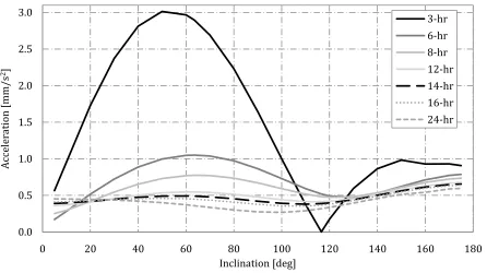
Fig. 1 Total acceleration magnitude to achieve sun-synchronous Taranis orbits of varying period and
inclination.
Fig. 1 shows that a natural sun-synchronous orbit exists without the use of any low-thrust propulsion. This occurs for a 3 h orbit at the conventional critical inclination of 116.6 deg. As the perigee altitude remains constant for all orbits in Fig. 1, only one natural sun-synchronous exists i.e. the 3 h orbit. Thus, the other results shown in Fig. 1 are an extension of this solution, and are only enabled through the use of continuous acceleration. For improved high-latitude observation the most beneficial inclination is 90 deg in the case of a 12 h orbit, the orbit considered in previous publications [4, 5], the total constant acceleration magnitude required is 0.478 mm/s2. In this case, the majority of the acceleration is in the normal direction (0.470 mm/s2). Thus, for a 1-ton spacecraft a maximum thrust of 478 mN is required, which will decrease as the propellant is consumed a variable thrust SEP system is therefore required Although the maximum thrust is higher than the thrust required to achieve a 90 deg inclination Taranis orbit without the sun-synchronous condition (81 mN) this level of thrust is achievable using current or near-term technology. For example, the High Power Electric Propulsion thruster which has undergone ground testing is capable of providing a maximum of 670 mN, [10] and test data from the Nuclear Electric Xenon Ion System has also shown a maximum thrust level of 476 mN [11].
0.0 0.5 1.0 1.5 2.0 2.5 3.0
0 20 40 60 80 100 120 140 160 180
A
cc
el
er
ation
[mm/s
2]
Inclination [deg]
9
Fig. 1 also shows that as the orbital period increases, the acceleration magnitude decreases. To reach an inclination of 90 deg a 24 h orbit requires a constant acceleration of 0.275 mm/s2, while a 6 h orbit requires a constant acceleration magnitude of 0.865 mm/s2. Thus, lower orbit periods are expected to require development in SEP technology before they become feasible.
B. Change in Orbital Elements
Analytical solutions are developed for the remaining orbital elements, to ensure the desired zero secular rate of change of orbital elements is maintained in the presence of continuous acceleration.
1. Semi-Major Axis
2 22
2 2 2
sin
1 r t
J F J F
da pr p
R e T
d
e
r
(18)
Substituting expressions for the perturbing accelerations gives
4
2 2 2
2
3 2
2 4
4 2
4
2 2
2
4
4 2
3 1 cos 1 3 sin sin
1
2 1 sin
1 cos 2 1
3 1 cos sin sin2
1 cos
2 1
e
r
e t
J R e i
da
a e e F
d e a e
J R e i
e F
a e
(19)
Integrating Eq. (19) over one revolution to give the change in semi-major axis as
20 0
a
(20)
2. Eccentricity
2 2
2
sin 1 cos
r r
J F J F
de r r re
R T
d
p
p
p
(21)
[image:9.612.79.501.387.474.2]
42 2 2
2 2
2 4 2 4
4 2
2 2
4
4 2
3 1 cos 1 3 sin sin
1
1 sin
1 cos 2 1
3 1 cos sin sin2
1
cos 1
1 cos 1 cos 2 1
e r
e t
J R e i
de
a e F
d e a e
J R e i
e
F
e e a e
(22)
Integrating over one revolution, the change in eccentricity is
20 0
e
(23)
3. Inclination
23 cos n J F di r N
d p (24)
Substituting the normal perturbation, Eq. (24) becomes
2 4
2 2 2
2
3 4
4 2
1 cos 3 1 cos sin 2 sin
1 cos 2 1
e n
a e J R e i
di
F
d e a e
(25)
Once more, the locally optimal control law states that the normal thrust switches sign depending on argument of latitude; consequently Eq. (25) is integrated over one orbit using both argument of perigee equal to 0 deg and 270 deg gives the change in inclination respectively
2 2
0
0 deg 4a Fnsin
i
(26)
2 2
2 2 20 2 2 2 2
270deg
1 1 1 1
cos 4 1 2 1 12 Arctanh 3 ln 3 ln
1 n 1 1 1
e e e
i a F e e e e e e
e e e e
(27)
Inserting values of orbital elements gives the change in inclination for both cases as
2 0i
11
Thus, these analytical solutions show no adverse affect on any of the orbital elements through the application of continuous low-thrust.
C. Special Perturbations Technique
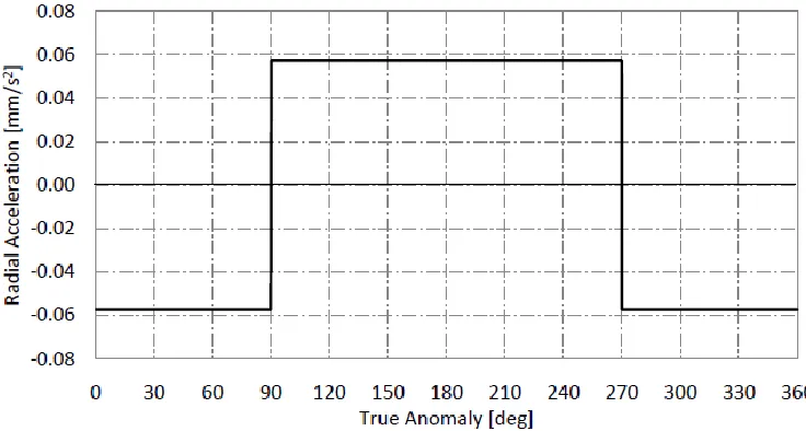
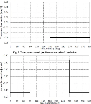
[image:11.612.129.497.297.494.2]To verify the solutions generated using the general perturbations method, a special perturbations solution is generated. This numerical model propagates the position of the spacecraft,with initial conditions given in Table 1, using a set of Modified Equinoctial Elements [12], using an explicit variable step size Runge Kutta (4,5) formula, the Dormand-Prince pair [13]. Numerical simulations include only perturbations due to Earth oblateness to the order of J2 and relative and absolute error tolerances are set to 10-8. The acceleration control profiles, given from the locally optimal control laws, to maintain the 12 h, 90 deg incliantion Taranis orbit are given in Fig. 2 - Fig. 4.
Fig. 3 Transverse control profile over one orbital revolution.
Fig. 4 Normal control profile over one orbital revolution.
13
be introduced into the orbit, thus increasing the tolerances to thrust failure significant investigation of this is however, out with the sope of this work.
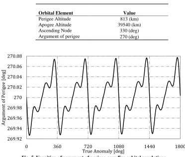
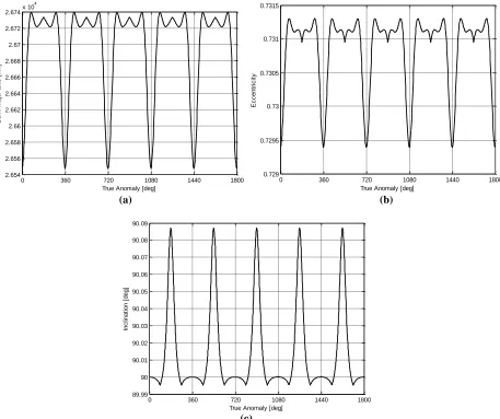
The numerical model verifies that the change in argument of perigee is negligible over one orbit revolution, and the change in ascending node angle is approximately equal to 1 deg per day, this is shown in Fig. 5 and Fig. 6 respectively. The numerical model also confirms that the change in semi-major axis, eccentricity and inclination are negligible over one orbit revolution. The change in semi-major axis, eccentricity and inclination over five orbital revolutions are shown in Fig. 7.
Table 1 Orbital parameters.
Orbital Element Value
Perigee Altitude 813 (km)
Apogee Altitude 39540 (km)
Ascending Node 330 (deg)
[image:13.612.116.488.251.567.2]Argument of perigee 270 (deg)
Fig. 5 Varaition of argument of perigee over five orbital revolutions.
269.92 269.94 269.96 269.98 270 270.02 270.04 270.06 270.08
0 360 720 1080 1440 1800
A
rgume
nt
of
Pe
rige
e
[de
g]
Fig. 6 Variation of longitude of ascending node over five orbital revolutions.
(a) (b)
(c)
Fig. 7 Oscillation of orbital elements over five orbital revolutions: a) semimajor axis, b) eccentricity, and c)
330 330.5 331 331.5 332 332.5
0 360 720 1080 1440 1800
A
sc
en
din
g
N
ode
[de
g]
True Anomaly [deg]
0 360 720 1080 1440 1800
2.654 2.656 2.658 2.66 2.662 2.664 2.666 2.668 2.67 2.672
2.674x 10
4
True Anomaly [deg]
S
e
m
i-m
a
jo
r
a
x
is
[
k
m
]
0 360 720 1080 1440 1800
0.729 0.7295 0.73 0.7305 0.731 0.7315
True Anomaly [deg]
E
c
c
e
n
tr
ic
it
y
0 360 720 1080 1440 1800
89.99 90 90.01 90.02 90.03 90.04 90.05 90.06 90.07 90.08 90.09
True Anomaly [deg]
In
c
lin
a
ti
o
n
[
d
e
g
[image:14.612.81.538.302.685.2]15
III.
Conclusion
The use of continuous low-thrust propulsion has been shown to enable highly elliptical sun-synchronous orbits around the Earth, termed sun-synchronous Taranis orbits. Continuous, constant acceleration is used to alter both the natural critical inclination of highly elliptical orbits to any inclination, and to maintain the sun-synchronous orbit condition. As such, a highly elliptical sun-synchronous orbit inclined at 90 deg can be enabled, allowing improved high-latitude imaging and simplified instrument design through simplification of the thermal environment. To enable a 12 h, 90 deg inclination orbit a total acceleration of around 0.5 mm/s2 is required, although this is significantly higher than the acceleration required to enable a highly elliptical orbit with an inclination of 90 deg without the sun-synchronous condition (0.081 mm/s2), it is likely to be achievable using current or near term technology, for example the High Power Electric Propulsion Thruster.
References
1. Lazzara, M. A., Stearns, C. R., Staude, J. A., and Knuth, S. L. "10 Years of Antarctic Composite Images," 7th Conference on Polar Meteorology and Oceanography and Joint Symposium on High-Latitude Climate Variations. Vol. Paper 9.4, American Meteorological Society, Boston, MA, Hyannis, MA, 2003, 12-16 May 2003.
2. Pieri, D. C. "Virtual Polar Geostationary Satellite (VPGS): A Trade Study for the NASA Earth Science Technology Office.." Earth and Science Division Jet Propulsion Laboratory California Institute of technology Pasadena, CA. 3. "World Meteorological Organization vision for the GOS in 2025", Consulative Meetings on High-Level Policy on
Satellite Matters Ninth Session, 2009.
4. Anderson, P., and Macdonald, M. "Extension of Highly Elliptical Earth Orbits using Continuous Low-Thrust Propulsion", Journal of Guidance, Control and Dynamics, Accepted November 2011.
5. Anderson, P., and Macdonald, M. "Static Highly Elliptical Orbits using Hybrid Low-Thrust Propulsion ", Journal of Guidance, Control and Dynamics, Submitted October 2011.
6. Anderson, P., and Macdonald, M. "Continuous Remote Sensing of Polar Regions from a Taranis Orbit Constellation",
Journal of Atmospheric and Oceanic Technology, Submitted April 2012.
7. Macdonald, M., McKay, R. J., Vasile, M., and Bosquillon de Frescheville, F. "Extension of the Sun-synchronous Orbit", Journal of Guidance, Control and Dynamics Vol. 33, No. 6, 2010, pp. 1935-1940.
8. Fortescue, P., Stark, J., and Swinerd, G. Spacecraft Systems Engineering. England: John Wiley & Sons Ltd. Chichester, West Sussex, England, 2003. pp 94.
9. Macdonald, M., and McInnes, C. R. "Analytical Control Laws for Planet-Centered Solar Sailing", Journal of Guidance, Control and Dynamics Vol. 28, No. 5, 2005, pp. 1038-1048.
10. Forster, J. E., Haag, T., Patterson, M., Williams, G. J., Sovey, J. S., Carpenter, C., Kamhawi, H., Malone, S., and Elliot, F. "The High Power Electric Propulsion (HiPEP) Ion Thruster", 40th Joint Propulsion Conference and Exhibit, 2004. 11. Randolph, T. M., and Polk, J. E. "An Overview of the Nuclear Electric Xenon Ion System (NEXIS) Activity.", 40th
AIAA/ASME/SAE/ASEE Joint Propulsion Conference, 2004.
12. Walker, M. J. H., Ireland, B., and Owens, J. "A set of Modified Equinoctial Orbital Elements", Celestial Mechanics
Vol. 36, 1985, pp. 409-419.