Abstract— Passive damping is the most adopted method to
guarantee the stability of LCL-filter based grid-converters. The method is simple and, if the switching and sampling frequencies are sufficiently high, the damping losses are negligible. This letter proposes the tuning of different passive damping methods and an analytical estimation of the damping losses allowing the choice of the minimum resistor value resulting in a stable current control and not compromising the LCL-filter effectiveness. Stability, including variations in the grid inductance, is studied through root locus analysis in the z-plane. The analysis is validated both with simulation and with experiments.
Index Terms— Passive damping, LCL-filter, stability,
voltage-source converter.
I. INTRODUCTION
ASSIVE damping is the most adopted method to guarantee the stability of the LCL-filter based grid-converters. Neither new sensors nor changes in the control software for the
L-filter case are necessary but there are additional
encumbrances and losses that could claim for forced cooling [1]. Active damping modifies the control to obtain stability without using dissipative elements. The damping losses are avoided at the price of increased complexity in the control design and/or implementation [2]-[3], moreover sometimes new sensors are added [4]-[5]. This letter reviews the passive damping methods [6]-[7] and proposes an analytical estimation of the losses to select the best configuration resulting in stability without compromising the LCL-filter effectiveness. Stability analysis, including for grid inductance variations, uses root locus in the z-plane.
Manuscript received April 27, 2012.
R. Peña-Alzola is with the Department of Energy Technology, Aalborg University, DK-9220 Aalborg East, Denmark (e-mail: [email protected]).
M. Liserre is with the Department of Energy Technology, Aalborg University, DK-9220 Aalborg East, Denmark (e-mail: [email protected]).
F. Blaabjerg is with the Department of Energy Technology, Aalborg University, DK-9220 Aalborg East, Denmark (e-mail: [email protected]).
R. Sebastián is with the Department of Electrical, Electronic and Control Engineering, National University for Distance Learning, UNED, 28040-Madrid, Spain (e-mail: [email protected]).
J. Dannehl is with Danfoss Solar Inverters A/S, DK-6400 Sønderborg, Denmark (e-mail: [email protected]).
F. W. Fuchs is with the Institute for Power Electronics and Electrical Drives, Christian-Albrechts-University of Kiel, 24143 Kiel, Germany (e-mail: [email protected]).
II. PASSIVE DAMPING DESIGN
A. Simple resistor case
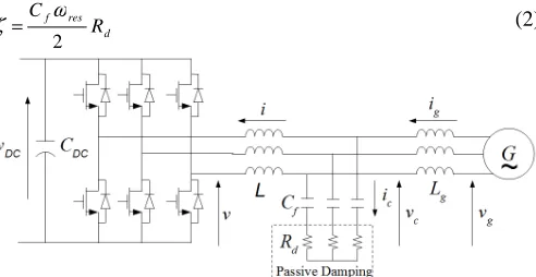
Fig. 1 shows a three phase LCL-filter based converter with passive damping for the simple resistor case. The transfer function Gpd(s), related to the converter voltage v and the converter current i, is [8]:
2 2
2 2
2 2 1 ) (
) ( ) (
res res
LC LC pd
ω + s ω + s
z + s z + s Ls = s v
s i = s G
ζ
ζ
′(1)
with zLC2=(LgCf)−1, ωres2=(2πfres)2=(1+Lg/L)zLC2 is the resonance frequency, Lg the grid inductance, L the converter inductance and Cf the filter capacitance. The damping factors are calculated as:
d res f
R C
2 ω
ζ = (2)
Fig. 1. LCL-filter based three phase converter using passive damping (simple resistor case).
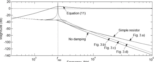
and ζ'=RdCfzLC/2 with Rd the damping resistor value. From (2) Rd has the order of magnitude of the LCL-filter capacitor impedance at ω=ωres. In the lower power range the switching frequency ωsw=2πfsw is selected larger than ωres [9]. The transfer function related to the grid current ig and v has a zero at z=−1/RdCf which decreases the attenuation for ω>>ωres from 60 dB/decade, see Fig. 2 for the case with no damping , down to 40 dB/decade, see Fig. 2 for the simple resistor case. Thus, Rd should be lower, or at least not much higher, than:
sw f dsw
f C R
π
2 1
= (3)
Analysis of the Passive Damping Losses in
LCL-filter Based Grid Converters
Rafael Peña-Alzola, Marco Liserre, Member, IEEE, Frede Blaabjerg, Fellow, IEEE, Rafael Sebastián,
Member, IEEE, Jörg Dannehl and Friedrich Wilhelm Fuchs, Senior Member, IEEE
[image:1.612.317.563.412.539.2]where Rdsw is the impedance of the filter capacitor at fsw so
ωsw<<1/RdCf. The current control uses a rotating dq-frame synchronous to the grid frequency. The current control uses a rotating dq-frame synchronous to the grid frequency. When considering the converter current i as feedback with a simple digital PI controller, the open loop transfer function results in:
dB) (0 1 )
( ) ( ) ( )
( = =
= =j res PI delays pd s j res
s
ol s G s G s G s
G
ω
ω (4)
where Gdelays(s) models the computational delay (one sampling period Ts=1/fs) and the PWM delay (half sampling period) and GPI(s) is the PI controller.
Fig. 2. Frequency response of the grid current ig versus the converter voltage v (case with no damping, simple resistor case and configurations shown in Fig. 3) and the ratio between ic and îc expressed in (11).
At low frequency the capacitor branch can be neglected and the LCL-filter behaves as an L-filter with the inductance value as LT=L+Lg the sum of the grid and converter inductances. This control dynamics remains unchanged with the introduction of passive damping, see [1] for details. Hence, the PI controller is tuned using the technical optimum criterion with integration time Ti=LT/RT and proportional gain
kp=LT/(3Ts) [8] for 4% overshoot (damping factor ζ =0.707) where RT=R+Rg is thesum of the grid and converter inductor resistances R and Rg respectively. As the phase-shift of −180º in Gol(s) is near ω=ωres [8], [10], the minimum damping resistor Rdmin for a stable system must comply (4) in order to achieve a positive gain margin in the control. To obtain a simple estimation for Rdmin the effect of the delays is neglected as |Gdelays(jωres)|≈1 for ωres<2πfs and the numerator of (1) is approximated to |s2+2ζ’zLCs+zLC2|≈|s2+zLC2| as ωres>zLC. After neglecting the smallest terms, it results in:
(
)
= + =
res f res
s g
g g s dmin
C f
f L L L
L L f R
ω π
1 6
1 3
1 2 (5)
From the assumed simplifications (5) will be accurate in the case of fs>>fres and Lg/L>>1. For fs≈2fres and Lg/L<2, Rdmin will be approximately 20% of the capacitor impedance value at ω=ωres which is coherent with the recommended value for the damping resistor [1] of about one-third of that value.
B. Complex passive damping methods
The damping losses Pd can be reduced by using additional passive elements in the capacitor branch, see Fig. 3. In Fig. 3a at the fundamental frequency ω=ωf the inductance Ld in
parallel with the resistor must provide a low impedance,
Ldωf<<Rd [7], so the fundamental losses Pdf are nullified. At
ω=ωres the resistor must have the dominant current flow path,
Rd<<Ldωres, for proper damping. The frequency response for Fig. 3a, and so the grid current THD, is very similar to that of the simple resistor case, see Fig. 2. In order to attain a proper trade-off the impedance ratio of the resistor Rd and the inductor Ld at ω=ωf and ω=ωres are made equal as:
d res d
f d
d
R L L
R ω
ω = (6)
Fig. 3b adds a parallel capacitor Cd to Fig. 3a for reducing the harmonic damping losses PdH [9] by short-circuiting the current harmonics around ω=ωsw so 1/(Cdωsw)<<Rd [7]. At
ω=ωres the resistor must be the dominant current flow path,
Rd<<1/(Cdωres), for a proper damping. As previously discussed, Cd can be:
(
)
(
d sw)
dd res d
C R R
C
ω ω
1 1
[image:2.612.50.299.215.316.2]= (7)
Fig. 3. Different configurations for passive damping.
III. ESTIMATION OF PASSIVE DAMPING LOSSES
A. Simple resistor case
As Rd<<Zcf, with Zcf the impedance of the filter capacitor at
ω=ωf, Rd can be neglected to calculate the capacitor fundamental current Icf. Thus, Pdf for unity power factor can be estimated as:
(
)
(
)
(
)
df f
nom g f nom
d cf cf d cf
df R
C I L V
R Z V R I
P 2
2 2
2 2
1 3 3
3 3
ω
ω
+
=
=
≈ (8)
[image:2.612.314.561.282.397.2] − +
− 3 4
2 3 8 9 2 3 8 9 3 4 2 3 48 1 3 2 1
ˆ m m
π m L f V = I sw DC lower RMS cH π (9)
where m is the modulation index calculated by neglecting the LCL-filter capacitor branch at ω=ωf as:
(
)
[
]
22 3 2 2 nom g f nom DC I L L V V
m + +
=
ω
(10)The ratio between ic and îc for the different harmonic frequencies nωf, with the nth harmonic order, is:
(
)
) ( ˆ ) ( 1 2 ) ( ˆ ) ( ) ( ˆ )( 2 2
f lower c f c jn s res res jn s c c jn s c c n I n I Ls ω + s ω + s L s s G s G s i s i f f f ω ω ζ ω ω ω = = = = = = (11)
where Ĝc(s) is the transfer function related to îc and v as well as Gc(s) is that related to ic and v. It can be seen in Fig. 2 that the frequency response of (11) is more than unity (>0 dB) for ω>>ωres and approaches to unity (0 dB). Then (9) is a lower bound of the LCL-filter capacitor rms harmonic current IcHRMS for ωsw>ωres. Thus, a lower approximationPdHlowerfor the harmonic damping losses PdH is:
(
)
dlower RMS cH lower
dH I R
P =3 2 (12)
Converter voltage harmonics, and so the current harmonics, appear as sidebands centered on the switching frequency and its multiples for linear modulation [11]. The current harmonic of order mf−6 is negligible for a large frequency modulation ratio mf=ωf/ωsw. Assuming (mf−6)ωf>ωres, an upper bound of
IcHRMS results:
− − = = −
= ˆ (( 6) )
) ) 6 (( ˆ ) ( ˆ ) ( ˆ ˆ ) 6
( f f
lower c f f c lower RMS cH ω m j s c c lower RMS cH upper RMS cH ω m I ω m I I s G s G I I f f (13)
Thereby, an upper approximation
P
dHupper for the harmonic damping losses PdH results in:(
)
dupper RMS cH upper
dH I R
P =3 2 (14)
For elevated fsw, (12) and (14) are very close to each other. The average of these values can be used to estimate PdH.
Although Rdmin for stability is proportional to fs in (5), PdH is inversely proportional to fsw in (12). However, fsw should not just be increased, since the switching losses are proportional to
fsw. Hence, the passive damping is an attractive approach versus active damping when elevated switching frequency is possible since the resulting damping losses are much reduced. For the same fsw, using double PWM update mode (fs=2fsw), it doubles the bandwidth [10] but doubles also Rdmin in (5)
thereby increasing the losses. As usually (L+Lg)<0.1 pu [1], Vcf will be close to Vnom in (8) and m will vary a little with the load in (10). Thus, Pd varies slightly with the load unlike the switching losses which are proportional to the load current.
B. Complex passive damping methods
In Fig. 3b the current through the whole capacitor branch can be estimated with (9) and (13) with Gc(s) calculated for the present configuration. As most important harmonics are around ω=ωsw, the current through the damping resistor can be estimated by the ratio of impedances at ω=ωsw. Therefore:
2 d d dH d R Z P
P ≈ (15)
where
d d d d
d R L C R
C
d Z Z Z Z Z
Z = || || ≈ || are impedances for ω=ωsw. Equation (15) is an upper approximation since higher harmonics will have lower ratios |Zd/Rd|. The frequency response for Fig. 3b does not degrade for ω>>ωres as much as in the simple resistor case and so the grid current THD improves, see Fig. 2.
In Fig. 3c most of the current harmonics bypasses the damping resistor branch by circulating through the parallel capacitor C [12]. Pd is reduced although the resistor value for the proper damping is higher than that of the simple resistor case. Reference [12] proposes equal capacitances in both branches Cd=C=Cf/2. Again Rd can be neglected in order to calculate Icf since Rd <<1/(Cdωf) and, with two parallel branches for Cd and C, the resulting current through Rd is halved so Pdf for Fig. 3c is a quarter of (8). To calculate PdH for Fig. 3c it must be proceeded as in (15) by considering the main harmonics around ω=ωsw. Hence, Pd results in:
2 4 d CT dH df d Z Z P P
P ≈ + (16)
where Zd =Rd+ZCd and ZCT=ZC||Zd are also the impedances for ω=ωsw. As previously discussed, (16) is also an upper approximation. In Fig. 3d [6] the inductor Ld is located in parallel to the damping resistor shown in Fig. 3c once more to annul the fundamental losses Pdf. The frequency responses for the circuits in Fig. 3c and Fig. 3d are very similar to that for the circuit in Fig. 3b, see Fig. 2.
IV. SIMULATION AND EXPERIMENTAL RESULTS The data of the LCL-filter based grid converter are: Lg=5 mH, L=3 mH, Cf=2.2 µF, Pnom=4.1 kW and Vnom=380 V. All details about the experimental setup along with relevant waveforms can be found in [1]. Table I shows that the estimation Rdmin (5) of the minimum damping resistor for stability is conservative and accurate only for elevated fsw as expected from the simplifications used. Table II and Table III show that the estimated losses are very close to those obtained by simulation (Matlab/Simulink). This is because the simulation models of the power devices and the passive elements are ideal. As expected from the assumptions used, the accuracy increases for increasing fsw. Table III also shows the grid current THD obtained by simulation.
TABLE I.MINIMUM DAMPING RESISTOR FOR STABILITY.
fsw 6 kHz 7 kHz 8 kHz 9 kHz
Calculated 2.6 Ω 5.1 Ω 7.2 Ω 8.9 Ω
Rdmin (5) 6.3 Ω 7.3 Ω 8.3 Ω 9.4 Ω
TABLE II.DAMPING LOSSES OBTAINED BY SIMULATION AND ESTIMATION FOR THE SIMPLE RESISTOR CASE (RD=10Ω).
fsw 5 kHz 6 kHz 7 kHz 8 kHz
Simulation(W) 41.5 25.8 18.0 13.4 Estimation(W) 41.1 25.4 17.7 13.2
TABLE III.DAMPING LOSSES, SIMULATION AND ESTIMATION, GRID CURRENT THD, SIMULATION, AND GRID INDUCTANCE VARIATION RESULTING IN
INSTABILITY FOR THE DIFFERENT CONFIGURATIONS (fsw=8 kHz). Simple
Resistor
Double Update
Fig. 3a
Fig. 3b
Fig. 3c
Fig. 3d
Add. Delay Simulation(W) 21.1 33.2 19.8 4.1 4.9 3.7 9.4 Estimation(W) 20.9 33.0 19.8 5.3 6.2 4.8 9.3
ig THD(%) 1.5 1.0 1.5 0.8 0.8 0.8 0.8
Lgreal/Lg 7.5 - 6.6 3.6 3.7 6.7 5.8
Fig. 4 shows the z-plane root locus for increasing Rd. Stability is attained for Rdmin=8.3 Ω (5), the threshold is Rdsw=9
Ω (3) and a proper damping (ζcl≈0.1 [8]) needs Rd =16 Ω. Double update mode doubles the bandwidth up to 848 Hz but it needs Rd=26 Ω and thereby increasing the damping losses. Although Rd>>Rdw this elevated bandwidth lowers the grid current THD. The reduction in Pd for Fig. 3a with Ld=7.2 mH (6) is small since Pdf was only 1.1 W. Pd and the grid current THD are substantially reduced for Fig. 3b with Cd= 2.2 µF (7). Fig. 3c needs Rd=80 Ω, notwithstanding, Pd and the current grid THD are much reduced. As expected (15) and (16) used for Figs. 3b, 3c and 3d result in upper approximations for Pd. Fig. 3d with Ld=36 mH (6) produces a modest improvement since Pdf was only 1.3 W. Inserting an additional delay requires Rd=7 Ω with a reduced bandwidth, 255 Hz, but an improved grid current THD as now Rd<Rdsw.
Fig. 5 shows the root locus in the z-plane by varying the real grid inductance Lgreal for the simple resistor case. Stability is assured for decreasing Lgreal with Lgreal=0, the L-filter case, inherently stable. Increasing Lgreal increases the damping of the dominant poles which resuls in lower overshoots and decreases the damping of the high frequency poles (2) until the system becomes unstable. However, this requires Lgreal/Lg>>1 to reduce ωres since the LCL-filter is designed with Lg/L>1 [1].
The analysis can be generalized for all the configurations except the double update mode that is stable for all Lgreal, see Table III last row. The benefits of the circuits in Figs. 3b and Fig. 3c are at the price of reduced robustness. Finally, an additional control delay reduces the stability as it was expected.
Fig. 4. Closed loop poles in the z-plane of the converter current control (fs=fsw=8 kHz) by varying the damping resistor value between Rdmin=8.3 Ω
and Rd=16 Ω.
Fig. 5. Closed loop poles in the z-plane of the converter current control (fs=fsw=8 kHz) for Rd=16 Ω by varying the grid inductance between Lgreal=0
and Lgreal=7.5Lg.
TABLE IV.DAMPING LOSSES OBTAINED BY EXPERIMENTS FOR THE SIMPLE RESISTOR CASE (RD=10Ω).
fsw 5 kHz 6 kHz 7 kHz 8 kHz Lower estimation (8)+(12) 29.5 20.7 15.4 12.0
Experimental(W) 32 20 13 10
V. CONCLUSIONS
This letter has focused on passive damping of LCL-filter based grid converters. The damping resistor value must result in stability without compromising the filter effectiveness. The provided analysis allows selecting this value and estimating the losses. The analysis is expanded to more complex methods that reduce the fundamental and/or harmonic components of the damping losses by using additional passive elements. The analysis in the z-plane shows the different robustness of each method when increasing the real grid inductance until the system becomes unstable.
REFERENCES
[1] M. Liserre, F. Blaabjerg and S. Hansen: "Design and control of an LCL-filter based three-phase active rectifier," in IEEE Trans. on Ind.
Applicat., vol.41, no.5, pp. 1281- 1291, Sept.-Oct. 2005.
[2] Y.A.-R.I. Mohamed, M. A-Rahman and R. Seethapathy: "Robust line-voltage sensorless control and synchronization of LCL-filtered distributed generation inverters for high power quality grid connection,"
IEEE Trans. on Power Electron., vol.27, no.1, pp.87-98, Jan. 2012.
[3] Y. Tang, P.C. Loh, P. Wang, F.H. Choo and F. Gao: "Exploring Inherent Damping Characteristic of LCL-Filters for Three-Phase Grid-Connected Voltage Source Inverters," IEEE Trans. on Power Electron., vol.27, no.3, pp.1433-1443, March 2012.
[4] M. Xue, Y. Zhang, Y. Kang, Y. Yi, S. Li and F. Liu: "Full Feedforward of Grid Voltage for Discrete State Feedback Controlled Grid-Connected Inverter With LCL Filter," IEEE Trans. on Power Electron., vol.27, no.10, pp.4234-4247, Oct. 2012.
[5] J. He and Y.W. Li: "Generalized Closed-Loop Control Schemes with Embedded Virtual Impedances for Voltage Source Converters with LC or LCL Filters," IEEE Trans. on Power Electron., vol.27, no.4, pp.1850-1861, April 2012
[6] K.H. Ahmed, S.J. Finney and B.W. Williams: "Passive Filter Design for Three-Phase Inverter Interfacing in Distributed Generation," in
Compatibility in Power Electron., CPE '07, pp. 1-9, 2007.
[7] T.C.Y. Wang, Zhihong Ye, Gautam Sinha and Xiaoming Yuan: "Output filter design for a grid-interconnected three-phase inverter," in IEEE
34th Annu. Power Electron. Specialist Conf., PESC '03, vol. 2, pp. 779-
784, 15-19 June 2003.
[8] M. Liserre, A. Dell'Aquila and F. Blaabjerg: "Stability improvements of an LCL-filter based three-phase active rectifier," in 2002 IEEE 33rd
Annu. Power Electron. Specialists Conf., PESC’02. Vol. 3, pp. 1195-
1201, 2002.
[9] A.A. Rockhill, M. Liserre, R. Teodorescu and P. Rodriguez: "Grid-Filter Design for a Multimegawatt Medium-Voltage Voltage-Source Inverter," in IEEE Trans. on Ind. Electron., vol.58, no.4, pp.1205-1217, April 2011.
[10] V. Blasko and V. Kaura: "A novel control to actively damp resonance in input LC filter of a three-phase voltage source converter," in IEEE
Trans. on Ind. Applicat., vol.33, no.2, pp.542-550, Mar 1997.
[11] D.G. Holmes and T.A. Lipo: Pulse width modulation for power
converters: principles and practice, Chapter 6. Pages: 291-294,
Wiley-IEEE Press, October 2003. ISBN: 978-0-471-20814-3.