Copyright © CIGRÉ 2014
Demonstration and analysis of IP/MPLS communications for delivering power system protection solutions using IEEE C37.94, IEC 61850 Sampled Values,
and IEC 61850 GOOSE protocols
S.M. BLAIR, F. COFFELE, C.D. BOOTH University of Strathclyde
UK
B. DE VALCK, D. VERHULST Alcatel-Lucent
Belgium
SUMMARY
Communications is becoming increasingly important for power system applications. Internet Protocol/Multiprotocol Label Switching (IP/MPLS) has the potential to significantly improve the performance and efficiency of power system communications compared with legacy time-division multiplexing (TDM) solutions, without sacrificing the reliability of safety-critical systems such as protection.
This paper reports on the requirements and performance of the conventional IEEE C37.94 and emerging IEC 61850 protocols for delivering current differential protection over an IP/MPLS network. Several configurations and parameters are investigated, and the paper highlights the key differences.
A number of trade-offs must be carefully observed when specifying IEEE C37.94 parameters to meet the latency and bandwidth requirements for each protection application. IEC 61850 Sampled Values requires greater bandwidth than IEEE C37.94, but the potential for improved and faster acting protection – such as for backup intertrip schemes, as demonstrated the paper – may justify its use for wide-area protection.
KEYWORDS
1 1. INTRODUCTION
Communications is becoming increasingly important for power system applications. Several new communications-enhanced protection and control schemes are emerging, including for managing the impact of distributed generation [1], for enabling fast-acting protection and restoration [2], [3], and for wide-area system monitoring and integrity [4], [5]. The use of the IEC 61850 standard offers many compelling advantages for these schemes, including high-speed Ethernet communications, a standardised data model, a standardised configuration methodology, and vendor interoperability [6].
Many types of power system protection have very stringent requirements for communications, specifically: low latency, symmetrical latency, and low jitter [7]. Conventionally, time-division multiplexing (TDM) has been used to minimise jitter and to provide dedicated bandwidth. These systems typically also offer resilience to link failure. However, TDM systems are inherently inflexible and make inefficient use of available bandwidth, particularly when multiple services – such as phasor measurement unit data, supervisory control and data acquisition (SCADA), voice telephony, and video surveillance – must be supported [8].
Internet Protocol/Multiprotocol Label Switching (IP/MPLS), a proven and widely deployed technology with service providers worldwide, is already seeing adoption in the power industry and in other sectors. IP/MPLS networks can provide significant improvements in network flexibility, efficiency, and ease of management – and in a cost-effective manner. For example, quality of service and traffic management ensure that critical services, such as protection, can be prioritised over other traffic and are provisioned with sufficient bandwidth [9]. Furthermore, IP/MPLS supports carrying both traditional circuit-switched and more modern packet-based traffic.
This paper demonstrates and analyses the use of commercial IP/MPLS and protection relay hardware to support power system protection functions using multiple protocols: IEEE C37.94 [10], IEC 61850-9-2 Sampled Values (SV) [11], and IEC 61850-8-1 Generic Object-Oriented Substation Event (GOOSE) [12].
2. IP/MPLS FOR POWER SYSTEM PROTECTION
IP/MPLS has many compelling applications in power system communications. The overall motivation for using IP/MPLS for power system protection is to improve efficiency in multiple areas:
1. A teleprotection “c-pipe” creates the effect of a dedicated time-division multiplexing (TDM) link, using the Pseudo Wire Emulation Edge-to-Edge (PWE3) architecture [13]. An emulated TDM pseudo wire over IP/MPLS does not suffer from the potential bandwidth inefficiency which can be associated with TDM; IP/MPLS only uses the bandwidth when data has to be sent, contrary to TDM where a time channel is reserved at all times.
2. IP/MPLS offers significantly better operational flexibility than TDM technology: provisioning a new protection service or modifying an existing service is a straightforward task in an IP/MPLS network. In a TDM environment, it is more cumbersome due to the static assignment of the time slots.
2 3.1. Utilities do not have to procure and maintain separate TDM and IP equipment; instead a single IP/MPLS router fulfils both roles. Tailored hardware interfaces for the IP/MPLS equipment ensure that legacy substation equipment does not need to be replaced, but can take advantage of an IP/MPLS network.
3.2. A single IP/MPLS network reduces the diversity in management software, staff training requirements, and physical footprint (i.e., rack space usage).
4. IP/MPLS is a future-proof solution, contrary to legacy TDM technology where products are experiencing end-of-lifecycle issues. Telecommunications service providers are increasingly abandoning leased lines services, creating difficulties for pure TDM deployments.
IP/MPLS can also substantially improve communications performance. Adding MPLS to an IP packet-based network makes it connection-oriented, similar to TDM, with deterministic label-switched paths. Further enhancing this with quality of service (QoS) ensures prioritization and correct operation of protection services in failure situations when the available bandwidth is scarce. The power industry is, however, relatively conservative in investing in new technologies, particularly for safety-critical system such as protection.
3. HARDWARE IN THE LOOP DEMONSTRATION
3.1. Overview
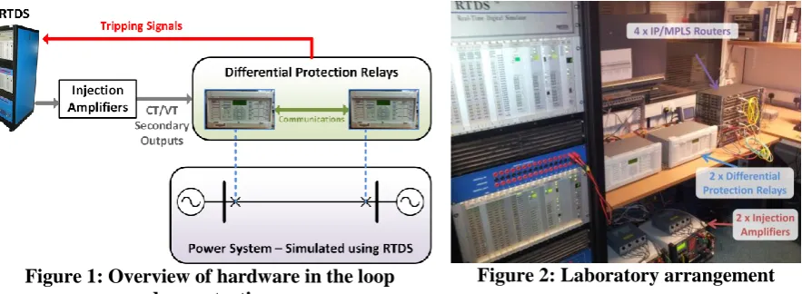
A hardware in the loop demonstration is a powerful technique for testing real devices under many possible scenarios [14], [15]. Figure 1 illustrates the hardware in the loop arrangement for the studies described in this paper. Two commercially-available current differential protection relays implement differential protection for a two-terminal line. The power system has been simulated using a real-time digital simulator (RTDS) which can interface with the hardware protection relays. An RTDS allows power system faults and other events to be simulated in real-time, and the response of the relays can be monitored in detail. The full laboratory arrangement is shown in Figure 2.
[image:3.595.80.522.498.660.2]Figure 1: Overview of hardware in the loop demonstration
Figure 2: Laboratory arrangement
3.2. Integrating IP/MPLS Communications
3.2.1. IEEE C37.94
3 service aggregation routers. Each IP/MPLS router is fitted with a voice and teleprotection interface card for direct connection to the protection relays, as illustrated in Figure 3.
Figure 3: Simplified IP/MPLS network for differential protection
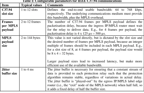
A direct, full-duplex optical link has been used for the physical connections between the IP/MPLS routers; other transport technologies, such as microwave and digital subscriber line (DSL), are also possible. Reference [16] discusses the performance of differential protection using IP/MPLS over legacy DSL links. A “c-pipe” service has been configured within the IP/MPLS routers to emulate a TDM service. Table I describes the parameters which have been investigated.
Table I: Configurable parameters for IEEE C37.94 communications
Item Typical values Comments
C37.94 slot size
1 to 12 slots Defines the end-to-end usable bandwidth: 64 to 768 kbps, respectively. The underlying communications medium must provide this bandwidth, plus the MPLS overhead.
Frames per MPLS payload
2 to 12 frames The number of C37.94 frames per MPLS payload defines the packetisation delay, because the ingress IP/MPLS router must wait for the relay to deliver data. E.g., for 4 frames per payload, the packetisation delay is 4 x 125 µs = 500 µs.
MPLS payload size
2 to 144 bytes This value is not varied directly, but is dictated by the slot size and the desired number of frames per MPLS payload, because an integer multiple of frames should be included in each MPLS payload. E.g., for a slot size of 8, at 4 frames per payload, the payload size would be 8 x 4 = 32 bytes.
Larger payload sizes lead to increased latency, but make more efficient use of the available bandwidth.
Jitter buffer size
1 to 4 ms The jitter buffer is necessary for ensuring that a constant stream of data is provided to each protection relay such that the protection algorithm remains stable, regardless of variations in actual delay. The jitter buffer is “played-out” by the egress IP/MPLS label edge router (i.e., the “exit” node of the MPLS network) when half full, so it adds a fixed delay of half the buffer size.
3.2.2. IEC 61850-9-2 Sampled Values
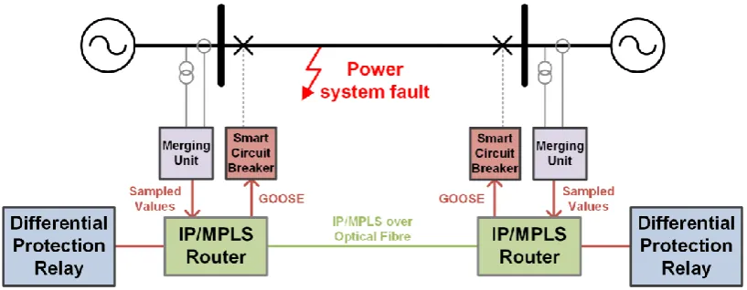
[image:4.595.65.530.396.696.2]4 for wide-area SV communications using IP/MPLS. Figure 4 illustrates the laboratory arrangement for using packet-based IEC 61850 SV rather than TDM-based IEEE C37.94. Each merging unit is responsible for generating time-synchronised SV packets from the measured voltage and current waveforms according to the recommendations in [17] (to be superseded by IEC 61869-9). For protection applications, this leads to approximately 5-6 Mbps of bandwidth required per SV stream. Each protection relay analyses the SV data from each end of the protection line, and transmits GOOSE messages containing the trip status. The “smart” circuit breakers are responsible for subscribing to the appropriate relay trip GOOSE messages to actuate the circuit breaker trip coil after the trip data attribute is set.
Figure 4: Differential protection using SV and GOOSE over IP/MPLS
A virtual private LAN service (VPLS) has been configured to transport the Ethernet-layer SV and GOOSE data over the (emulated) wide-area IP/MPLS network. An “e-pipe” service would also be suitable for this application. It is also possible to encapsulate SV and GOOSE packets within routable layer-3 IP packets, as described in IEC 61850-90-5; this is not necessary for a pure IP/MPLS network (which also has the benefit of constant latency due to the deterministic label-switched paths and packet prioritisation).
For this arrangement, prototype protection relays which support SV and GOOSE communications and the smart circuit breakers have been implemented on microcontrollers, using the method described in [6].
3.3. IP/MPLS Network Redundancy
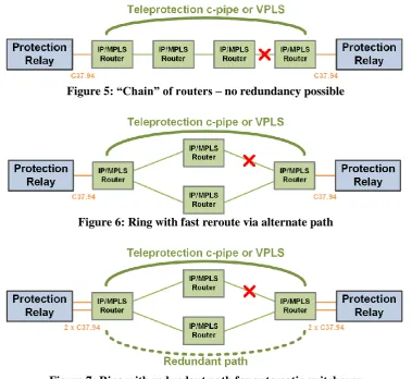
There are three main ways of organising the IP/MPLS network, in terms of the redundancy provided:
1. A simple “chain” without redundant paths (Figure 5), 2. A ring or mesh with automatic fast reroute (Figure 6), or
3. A ring or mesh with explicitly-defined redundant data streams (Figure 7).
5 Figure 5: “Chain” of routers – no redundancy possible
[image:6.595.108.488.71.419.2]Figure 6: Ring with fast reroute via alternate path
Figure 7: Ring with redundant path for automatic switchover
With full redundancy (Figure 7), the switchover process is instantaneous and automatic; the protection relays select the data stream with the lowest delay. The drawback of full redundancy is that dedicated bandwidth is used simultaneously on both paths.
Note that duplication of the IEEE C37.94 physical optical interface, as depicted in Figure 7, is not necessary – particularly if using SV instead, which is a multicast Ethernet protocol – but it provides further hardware redundancy.
4. RESULTS AND ANALYSIS
4.1. IEEE C37.94 Delay and Jitter Analysis
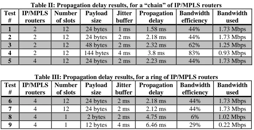
Table II and Table III provide a cross-section of typical results which illustrate the trade-offs in the design of the communications system:
Comparing Tests 1 and 2, it can be seen that increasing the jitter buffer size – which may be necessary for protection stability – increases the measured propagation delay. As illustrated by Test 4, a large payload size improves bandwidth efficiency, but a
relatively large jitter buffer is necessary to offset the packetisation delay.
6 Increasing the number of C37.94 slots helps to reduce the propagation delay, at the
[image:7.595.81.517.111.334.2]expense of increased bandwidth requirements.
Table II: Propagation delay results, for a “chain” of IP/MPLS routers Test # IP/MPLS routers Number of slots Payload size Jitter buffer Propagation delay Bandwidth efficiency Bandwidth used 1 2 12 24 bytes 1 ms 1.58 ms 44% 1.73 Mbps 2 2 12 24 bytes 2 ms 2.18 ms 44% 1.73 Mbps 3 2 12 48 bytes 2 ms 2.32 ms 62% 1.25 Mbps 4 2 12 144 bytes 4 ms 3.8 ms 83% 0.93 Mbps 5 4 12 24 bytes 2 ms 2.23 ms 44% 1.73 Mbps
Table III: Propagation delay results, for a ring of IP/MPLS routers Test # IP/MPLS routers Number of slots Payload size Jitter buffer Propagation delay Bandwidth efficiency Bandwidth used 6 4 12 24 bytes 2 ms 2.18 ms 44% 1.73 Mbps 7 4 12 24 bytes 2 ms 2.12 ms 44% 1.73 Mbps 8 4 1 2 bytes 2 ms 4.75 ms 6% 1.02 Mbps 9 4 1 12 bytes 4 ms 6.46 ms 29% 0.22 Mbps
For Tests 1 to 7, in the worst case (with full redundancy) the link utilisation was 0.36% of the available bandwidth of 1 Gbps. In Tests 8 and 9, the link bandwidth was artificially reduced to 2 Mbps and 1 Mbps, respectively; the payload size was consequently reduced to meet the reduced bandwidth. Although relatively low bandwidth use is possible, it can be seen that the use of bandwidth is relatively inefficient (each payload requires 30 bytes of MPLS overhead) and that the propagation delay is generally higher; the increased delay may be unacceptable for some protection applications.
With several parameters to configure, it is often not clear how to select the best compromise, particularly when bandwidth is constrained. This additional complexity is undesirable to utilities.
4.2. IEC 61850 Sampled Values and GOOSE
SV streams require significantly more bandwidth than IEEE C37.94: 5-6 Mbps compared with 64-768 kbps (before MPLS encapsulation). For two-terminal protection, as depicted in Figure 4, 0.54% of the IP/MPLS link bandwidth is required. Nevertheless, SV transfers much more information –the full three-phase voltage and current waveforms – which is potentially useful for future faster-acting protection applications, compared with the fundamental component current phasors [16] which are transferred using the IEEE C37.94 protocol. SV also requires accurate time-stamping within each merging unit; this is not typically necessary with IEEE C37.94-based relays, which instead require that the propagation delay is symmetrical and that the delay variation is eliminated.
7 considerable improvement in backup intertrip times. Using IP/MPLS, GOOSE packets to not suffer the inherent delays involved with IEEE C37.94 and can be prioritised above other traffic.
Table IV: Comparison of protocol trip times and bandwidth
IEEE C37.94 IEC 61850 SV and GOOSE
Fault occurs (ms) 0.0 0.0
Trip message sent (ms) n/a 23.4
Circuit breaker tripped (ms) 28.4 24.9
Backup intertrip (ms) 39.5 24.9
Bandwidth used (Mbps) 0.5 5.4
5. CONCLUSIONS
IP/MPLS has the potential to significantly improve the efficiency of power system communications compared with legacy TDM solutions, without sacrificing performance or reliability. MPLS technology is already seeing adoption with several utilities.
This paper has reported on several configurations and parameters under investigation. A number of trade-offs must be observed when specifying IEEE C37.94 parameters to meet the latency and bandwidth requirements for each application.
The paper has highlighted the differences in the requirements and performance of the IEEE C37.94 and IEC 61850 SV/GOOSE protocols for delivering current differential protection over an IP/MPLS network. Sampled Values clearly requires greater bandwidth than IEEE C37.94, but the potential for improved protection performance – such as for reducing the latency of backup intertrip schemes – may justify its use for wide-area protection.
BIBLIOGRAPHY
[1] A. Timbus, M. Larsson, and C. Yuen, “Active Management of Distributed Energy Resources Using Standardized Communications and Modern Information Technologies,” IEEE Trans. Ind. Electron., vol. 56, no. 10, pp. 4029–4037, Oct. 2009. [2] M. Yalla, M. Adamiak, A. Apostolov, J. Beatty, S. Borlase, J. Bright, J. Burger, S.
Dickson, G. Gresco, W. Hartman, J. Hohn, D. Holstein, A. Kazemi, G. Michael, C. Sufana, J. Tengdin, M. Thompson, and E. Udren, “Application of peer-to-peer communication for protective relaying,” IEEE Trans. Power Deliv., vol. 17, no. 2, pp. 446–451, Apr. 2002.
[3] B. Pickett, T. Sidhu, S. Anderson, A. Apostolov, B. Bentert, K. Boers, O. Bolado, P. Carroll, S. Chano, A. Chaudhary, F. Cobelo, K. Cooley, M. Cooper, R. Cornelison, P. Elkin, A. Elneweihi, R. Garcia, K. Gardner, T. Kern, B. Kasztenny, G. Michel, J. Niemira, T. Nissen, S. Charles, D. Ware, and F. Plumptre, “Reducing Outage Durations Through Improved Protection and Autorestoration in Distribution Substations,” IEEE Trans. Power Deliv., vol. 26, no. 3, pp. 1554–1562, Jul. 2011. [4] M. G. Seewald and R. G. Lobo, “Scalable Network Architechture based on IP
Multicast for Synchrophasor Applications,” PAC World Magazine, Dec-2013.
8 [6] S. M. Blair, F. Coffele, C. D. Booth, and G. M. Burt, “An Open Platform for
Rapid-Prototyping Protection and Control Schemes with IEC 61850,” IEEE Trans. Power Deliv., vol. 28, no. 2, pp. 1103–1110, 2013.
[7] P. Beaumont, F. Kawano, A. Kawarada, T. Kase, H. Sugiura, F. Lam, J. Hurd, P. Worthington, D. Richards, and P. Merriman, “Performance evaluation of current differential relays over a wide area network,” in 11th IET International Conference on Developments in Power Systems Protection (DPSP 2012), 2012, pp. 152–152.
[8] Alcatel-Lucent, “Reliable IP Communication for Smart Grids - Network transformation to IP/MPLS infrastructures,” 2010.
[9] Iometrix, “Teleprotection over IP/MPLS - Test Report,” 2011.
[10] IEEE, “C37.94-2002 - IEEE Standard for N Times 64 Kilobit Per Second Optical Fiber Interfaces Between Teleprotection and Multiplexer Equipment,” 2003.
[11] IEC TC 57, “Communication networks and systems in substations Part 9-2: Specific Communication Service Mapping (SCSM) - Sampled values over ISO/IEC 8802-3 (IEC 61850-9-2:2011).” 2011.
[12] IEC TC 57, “Communication networks and systems in substations Part 8-1: Specific Communication Service Mapping (SCSM) - Mappings to MMS (ISO 9506-1 and ISO 9506-2) and to ISO/IEC 8802-3 (IEC 61850-8-1:2011).” 2011.
[13] S. Bryant and P. Pate, “Pseudo Wire Emulation Edge-to-Edge (PWE3) Architecture,” RFC 3985, 2005. [Online]. Available: http://www.ietf.org/rfc/rfc3985.txt.
[14] S. Loddick, U. Mupambireyi, S. M. Blair, C. D. Booth, X. Li, A. J. Roscoe, K. Daffey, and J. Watson, “The Use of Real Time Digital Simulation and Hardware in the Loop to De-Risk Novel Control Algorithms,” in IEEE Electric Ship Technologies Symposium, 2011.
[15] F. Coffele, S. M. Blair, C. D. Booth, J. Kirkwood, and B. Fordyce, “Demonstration of Adaptive Overcurrent Protection Using IEC 61850 Communications,” in CIRED, 2013. [16] S. M. Blair and C. D. Booth, “Real-time teleprotection testing using IP/MPLS over xDSL,” University of Strathclyde, 2013. [Online]. Available: https://pure.strath.ac.uk/portal/files/26184600/001_DSL_Testing.pdf.
[17] UCA International Users Group, “Implementation Guideline for Digital Interface to Instrument Transformers Using IEC 61850-9-2,” 2004.