Experimental ship motion and load measurements in head and beam seas
8
0
0
Full text
(2) wave amplitudes at different wave headings and the work was improved in 2003 with global wave load predictions. In order to evaluate the method used, the results of vertical bending moment, horizontal bending moment, dynamic torsion and shear force were correlated with model test results. Within EU project DEXTREMEL six degrees of freedom motion response tests of a Ro-Ro model have been reported in regular waves for intact and damaged conditions by Korkut et al. (2005). Folso and Iaccarino (2005), within the MARSTRUCT project, studied the effect on hull girders of symmetric flooding considering the final equilibrium conditions and performed calculations in the frequency domain. Folso and Rizzuto (2008) presented the results of a numerical study for a damaged tanker using PRECAL three dimensional linear potential code from MARIN, comparing bending moment and torsion moments for intact ship and six damage scenarios. Santos and Guedes Soares (2006) presented a theory coupling ship motions with water on deck in the time domain. This was applied to the Ro-Ro passenger ship PRR1 used as a benchmark by ITTC. The water on deck was modelled by shallow water theory where the water flow is defined by non-linear hyperbolic equations offering an advantage in computation time without significant loss of accuracy compared to a standard CFD treatment with Navier-Stokes equations. The results of the theory are the intact and damaged ship roll RAOs, the shape of free surface and the phase of water motion in relation to the ship roll for different wave frequencies. The authors conclude that very often the damage has an adverse and non-linear effect on the structural loading and that the behaviour of the pressure values on the bulkheads which limit the damage is rather complex. The consequent conclusions and recommendations by the ISSC Damage Committee point towards more emphasis on research on the ship strength and safety assessment in the damaged condition.. The current paper focusses on the correlation of experimental results to the predictions of non-linear computations for intact and damaged conditions.. 2. EXPERIMENTAL INVESTIGATION. The experiments have been carried out at the Kelvin Hydrodynamic Laboratory University of Strathclyde Glasgow using a 1/100 scale model of a National US Navy Destroyer Hull 5415. Intact and damaged conditions, in regular waves at zero forward speed were investigated. The tests measured 6 degree of freedom motion responses of the model, as well as global loads for head and beam sea including also amplitude variations in order to investigate the non-linearities in ship responses. 2.1 Description of the facility and equipment used The towing tank is 76 metres long, 4.6 metres wide and has a water depth 2.15 metres. For the present experimental programme, waves were generated by multiflap type wave maker built by Edinburgh Designs Ltd. The wave maker employs force feedback mode within the electronic control system to stabilise operation and to obtain the desired transfer function, additionally the wave maker incorporate absorption facilities to remove the effects of reflected waves. The model was located in the centre of the tank both longitudinally and transversely. The wave elevation was monitored and recorded using one resistance probe around 15m from the wave maker and one ultrasonic wave probe close to the model. The six degree of freedom motions of the model were measured using a QUALISYS motion capture system. It is comprised of four infra-red reflectors strategically placed on the vessel (illuminated balls on Fig.1). The coordinates of the balls in 3D space are registered by four cameras suitably positioned near the vessel, and the six-degree-of-freedom motions are calculated and output in real time.. This paper presents an experimental program aimed at motion and load predictions for a sample vessel in intact and damage condition. The sample vessel is ITTC benchmark 5415 destroyer hull type. A general lay out and compartment modelling were prepared in order to get realistic subdivision to investigate on damage cases . The calculations by ShipX time domain code have been performed for each tested configuration. Figure 1: Model 5415 and experimental set up. IX HSMV Naples 25 - 27 May 2011. 2.
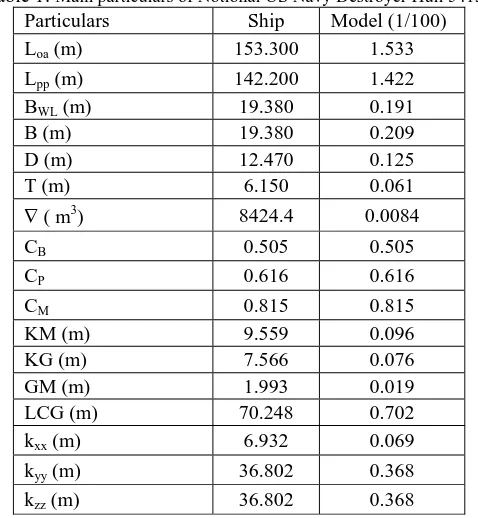
(3) 2.2 Construction of the model The segmented model was based on the offsets of a sample vessel of Notional US Navy Destroyer Hull 5415 and made from fibreglass. The main particulars of the model are given in Table 1, while the body plan of the model is shown in Figure 2.. 16. 14. The model was cut transversely, and the two sections made waterproof by the provision of a thin membrane across the cut. The forces and moments at the cut were obtained from a five component force gauge, type 206/5C manufactured by Danish Hydraulic Institute (DHI) with the following specifications: Fy=Fz=125N, My=Mz=110Nm and Mx=4.0Nm. The force gauge was bolted to two substantial bulkheads mounted in the fore and aft parts of the model. The gauge was located at 545 mm from AP longitudinally and at the centre of the depth which is 62.8 mm from the base line.. 12. 10. 2.3 Measurement of radii of inertia 8. 6. 4. 2. 0. -2 11 10. 9. 8. 7. 6. 5. 4. 3. 2. 1. 1. 2. 3. 4. 5. 6. 7. 8. 9. 10 11. Figure 2. DTMB 5415 Hull body plan. As the model had to be tested in damaged conditions as well as in intact condition, an appropriate damage size has to be decided. A two-compartment damage scenario was assumed and the model was damaged at the starboard side in the midship area. The details of damaged opening size and location are shown in Figure 3.. Figure 3. Model subdivision and flooded compartment definition. The longitudinal centre of gravity (LCG) of the model was obtained as 702.5 mm from AP. An inclining test was carried out to determine the vertical centre of gravity (KG) of the model. This indicated a transverse metacentric height GM value of 19.5 mm. Based on this value KG resulted as 75.6 mm.. IX HSMV Naples 25 - 27 May 2011. In order to adjust the radii of gyration of the model in pitch, yaw and roll, appropriate tests were performed. The pitch radius of gyration (kyy) was considered equal to the yaw radius of gyration (kzz) and therefore the swing test on bifilar suspension (Bhattacharyya (1978)) was used to assess kzz through the mean period of ten oscillations. The roll radius of gyration (kxx) was determined on the basis of 5 oscillations period free damping test in water. Both tests were repeated three times to obtain reasonable repeatability and the obtained radii of the bare model are given in the Table 1. Table 1: Main particulars of Notional US Navy Destroyer Hull 5415 Particulars Ship Model (1/100) Loa (m) 153.300 1.533 Lpp (m) 142.200 1.422 BWL (m) 19.380 0.191 B (m) 19.380 0.209 D (m) 12.470 0.125 T (m) 6.150 0.061 3 8424.4 0.0084 ∇(m) CB CP CM KM (m) KG (m) GM (m) LCG (m) kxx (m) kyy (m) kzz (m). 0.505 0.616 0.815 9.559 7.566 1.993 70.248 6.932 36.802 36.802. 0.505 0.616 0.815 0.096 0.076 0.019 0.702 0.069 0.368 0.368. 2.4 Description of test conditions and test trials The stationary model tests were carried out with both intact and damage conditions in head and beam waves. 90 tests were performed and their 3.
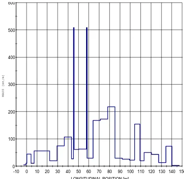
(4) identification is provided in Table 2. The steepness ratio H/λ was held constant for each test and equal to 1/50. For some frequencies the nonlinearities were investigated and the steepness ratio H/λ was increased gradually to its maximum defined by quality of waves or by ship behaviour and very violent responses. Table 2: Test matrix Test ID heading. condition. Freq range. H/l. R1 – R10 R11-R 20 R21-R 29 R30-R 41 R42-R 54 R55-R 61 R62-R 73 R74-R 83 R83-R 90. intact intact intact intact damage damage damage damage damage. 1.874-0.573 1.474-0.711 1.874-0.573 1.474-0.711 1.874-0.573 1.474-0.711 1.874-0.573 1.474-0.711 1.032&0.891. 1/50 varied 1/50 varied 1/50 varied 1/50 varied varied. 600. damage. 0.891. varied 500. Table 3 shows a summary of the experimental wave conditions and the corresponding full-scale conditions used in motion numerical calculations. Table 3: Waves description summary table ID Freq Aexp λ/L H/λ (Hz) (m) R1 1.874 0.3130 1/50 0.004 R2 1.586 0.4370 1/50 0.006 R3 1.474 0.5059 1/50,1/40;1/30 0.006 R4 1.305 0.8369 1/50,1/40;1/30 0.009 R5 1.146 1.0320 1/50 0.010 R6 1.032 1.8831 1/50,1/40;1/30 0.014 R7 0.891 2.1743 1/50,1/40;1/30 0.02 R8 0.764 2.6420 1/50 0.026 R9 0.711 3.3477 1/50,1/40;1/30 0.031 R10 0.645 0.3130 1/50 0.039 R11 0.573 0.4370 1/50 0.05. 3. Tsea (s) 5.336 6.305 6.784 7.663 8.726 9.690 11.223 13.089 14.065 15.504 17.452. 400. MASS [mt/m]. R87B-R 90B. Head sea Head sea Beam sea Beam sea Beam sea Beam sea Head sea Head sea Beam + Free drift Quartering +Free drift. hull form for these effects while the hydrodynamic coefficients of the ship hull are linear. For each test new calculation for ship full scale dimensions is performed as time domain simulation of 360 sec duration. The vessel mass distribution was described in ShipX as 2 D continuous longitudinal mass distribution. The ballast weight of model constituted about 5 kg of the total weight; the rest of the model mass, due to model structure, was distributed according to the sectional area curve. The weight of two aluminium bulkheads was estimated and inserted at the appropriate positions. The obtained mass distribution of intact ship used in calculation of loads at the position of force gauge is given in Figure 4.. 300. 200. Asea (m). 100. 0.4 0.6 0.9 1.0 1.4 2.0 2.6 3.1 3.9 5.0. TIME DOMAIN SHIPX CALCULATIONS. 0 -10. 0. 10. 20. 30. 40. 50. 60. 70. 80. 90. 100 110 120 130 140 150. LONGITUDINAL POSITION [m]. Figure 4. Mass distribution of intact ship. For the calculation of damaged ship the final flood equilibrium was described as loading condition. The measured values of immersion during tests was used in ShipX to find the real LCB position and actual trim of ship. New mass distribution was defined considering the flood water as the new mass along the flooded compartments, from after bulkhead x1 = 64.47 m to forward bulkhead x2 = 89.00 m. 600. 500. 400. MASS [mt/m]. SHIPX is MARINTEK’s common platform for ship design analyses. The system is a workbench environment that facilitates simple and efficient integration of different applications and components and the part of Vessel Responses Plug-In (VERES), was used in this work for defining model tests. The relatively new modulus “time domain calculations” was compared with the experimental results in order to get more information on the accuracy and sensitivity of the method. In the time domain simulations, non-linear effects due to restoring and Froude-Krylov forces are accounted for i.e. takes account for the above water. 300. 200. 100. 0 -10. 0. 10. 20. 30. 40. 50. 60. 70. 80. 90. 100 110 120 130 140 150. LONGITUDINAL POSITION [m]. Figure 5. Mass distribution of damaged ship IX HSMV Naples 25 - 27 May 2011. 4.
(5) PITCH RAO - INTACT 5415. The final equilibrium condition is given in Table 4.. 1.2 η5 / kA 1.0. Table 4. Two compartments damage loading condition Particulars Ship Lpp (m) 142.200 BWL (m) 19.380 Tmean (m) 7.140 Trim ( + aft) deg -0.159 8424.4 ∇ ( m3). 0.8 EXP-INTACT. 0.6. TD-INTACT STRIP THEORY. 0.4. Steepness variation. 0.2 λ/L. 0.0. D (t) LCG VCG. 4. 10381.6 69.774 7.144. 0.0. 0.5. 1.0. 1.5. 2.0. 2.5. 3.0. 3.5. 4.0. 4.5. 5.0. Figure 8. Pitch RAO in head sea. INTACT SHIP RESULTS. The head and beam sea conditions were considered with the stationary model moored elastically to the tank walls as shown in Figure 6.. Heave results in head sea show quite high discrepancy between experiment and calculation. The comparison between experiment and calculation for pitch is fair. It should be noted that there is no difference at all between strip theory results and time domain simulations and no sensitivity of time domain code to amplitude variations is observed. SHEAR FORCE RAO - INTACT 5415 0.150 FZ / (0.5ρgLBA). TD-FZ. 0.135 0.120. EXP_FZ. 0.105 TD - steepness variation. 0.090 EXP_steepness variation. 0.075 0.060 0.045 0.030 0.015. λ/L 0.000 0.0. 0.5. 1.0. 1.5. 2.0. 2.5. 3.0. 3.5. 4.0. Figure 9. Shear force RAO in head sea. Figure 6. Elastic mooring of model during tests. VERTICAL BENDING MOMENT RAO - INTACT 5415 0.06. 4.1 Head Sea. TD-MY. MY/ (0.5ρgL2BA). EXP_MY. 0.05. HEAVE RAO - INTACT 5415. TD - steepness variation. 0.04. 1.2. EXP_steepness variation. η3/A 1. 0.03. 0.8. 0.02. INTACT-HEAVE TD-INTACT. 0.6. 0.01. STRIP THEORY Steepness variation. 0.4. λ/L. 0.00 0.0. 0.5. 1.0. 1.5. 2.0. 2.5. 3.0. 3.5. 4.0. 0.2. Figure 10. Vertical bending moment in head sea. λ/L. 0 0.0. 0.5. 1.0. 1.5. 2.0. 2.5. Figure 7. Heave RAO in head sea. IX HSMV Naples 25 - 27 May 2011. 3.0. 3.5. 4.0. 4.5. 5.0. It can be seen that the shear force experimental results at λ/L = 0.5 vary significantly with amplitude variation. This sensitivity could be explained by the fact that is point close to the resonance frequency. All other points have extremely good correlation. It can be noted that for both shear force and bending 5.
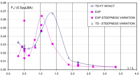
(6) moment the time domain simulation is reflecting the variation of wave amplitude. At the lowest wavelength simulation values are very high, the behaviour not expected in nature and not observed in experiments. It can be seen that overall trend of bending moment experimental results fits calculation values.. TORSIANAL MOMENT RAO - INTACT 5415 0.009 TD - MX_INTACT. 2. Mx/ (0.5ρgL BA). 0.008. EXP-MX-INTACT 0.007 EXP-STEEPNESS VARIATION 0.006 TD-STEEPNESS VARIATION 0.005 0.004 0.003 0.002. 4.2 Beam Sea. 0.001. λ/L. 0. ROLL RAO - INTACT 5415. 0.0. 12.0. 0.5. 1.0. 1.5. 2.0. 2.5. 3.0. 3.5. 4.0. TD-ROLL. η4 / kA. Figure 13. Torsion moment in beam sea. EXP_ROLL. 10.0. TD - STEEPNESS VARIATION. 8.0. ROLL-STRIP THEORY. HORIZONTAL BENDING MOMENT RAO - INTACT 5415. EXP-STEEPNESS VARIATION. 0.03. 6.0. TD - MZ INTACT. 2. MZ / (0.5ρgL BA) EXP. 4.0. 0.02. 2.0. 0.02. EXP-STEEPNESS VARIATION TD-STEEPNESS VARIATION. λ/L 0.0 0.0. 0.5. 1.0. 1.5. 2.0. 2.5. 3.0. 3.5. 0.01. 4.0. 0.01. Figure 11. Roll RAO in beam sea λ/L. 0.00. Discrepancies in calculation results between the strip theory and time domain approaches can be noted for the first time in the roll RAO in beam seas. It can be highlighted that the strip theory is perfectly matching the trend of experimental data but highly overestimates the peak value. Time domain results are shifted, the resonance frequency is not matched but the maximum value is reasonably predicted. Again there is no sensitivity of code predictions observed to the wave amplitude variations.. 0.0. 0.5. 1.0. 1.5. 2.0. 2.5. 3.0. 3.5. 4.0. Figure 14. Horizontal bending moment in beam sea. The prediction of the horizontal shear force and bending moment repeats the behaviour of roll RAO. If the maximum values are considered the numerical prediction is fair, but the peak frequency is not matched. As regard the torsion moment, relatively high discrepancies between numerical and experimental results can be noted.. HORIZONTAL SHEAR FORCE RAO - INTACT 5415. 5. 0.08 TD-FY INTACT. FY/ (0.5ρgLBA) 0.07. EXP EXP-STEEPNESS VARIATION. 0.06. TD - STEEPNESS VARIATION. DAMAGED SHIP RESULTS. 5.1 Head Sea Overall prediction of motions and loads of time domain code for damaged ship is very fair as can be seen in Figs. 15 – 18.. 0.05 0.04 0.03. HEAVE RAO - DAMAGED 5415. 0.02. 1.2. 0.01. η3/A. λ/L. 0.00 0.0. 0.5. 1.0. 1.5. 2.0. 2.5. Figure 12. Horizontal shear force in beam sea. 3.0. 3.5. 1.0 4.0. 0.8 DAMAGE-HEAVE TD-DAMAGE. 0.6. DAMAGE-STEEPNESS VAR. 0.4. EXP-STEEPNESS VARIATION. 0.2 λ/L. 0.0 0.0. 0.5. 1.0. 1.5. 2.0. 2.5. 3.0. 3.5. 4.0. 4.5. 5.0. Figure 15. Heave in head sea – two compartments damage. IX HSMV Naples 25 - 27 May 2011. 6.
(7) PITCH RAO - DAMAGED 5415. HORIZONTAL SHEAR FORCE RAO - DAMAGED 5415 0.06. 1.2. EXP - FY DAMAGE. FY/ (0.5ρgLBA). η5 / kA 0.05. 1.0. TD- FY DAMAGE EXP-STEEPNESS VARIATION. 0.04. 0.8 EXP -DAMAGE. TD-STEEPNESS VARIATION 0.03. TD-DAMAGE. 0.6. STRIP THEORY. 0.4. 0.02. DAM-STEEPNESS VARIATION EXP-STEEPNESS VARIATION. 0.01. 0.2. λ/L. λ/L 0.0. 0.00 0.0. 0.5. 1.0. 1.5. 2.0. 2.5. 3.0. 3.5. 4.0. 4.5. 5.0. 0.0. 0.5. 2.0. 2.5. EXP-DAMAGE. 0.007. TD-DAMAGE. 0.006. 0.135. 3.5. 4.0. TD - MX_DAMAGE. Mx/ (0.5ρgL2BA). 0.120. 3.0. TORSION MOMENT RAO - DAMAGED 5415. SHEAR FORCE RAO - DAMAGED 5415 FZ / (0.5ρgLBA). 1.5. Figure 20. Horizontal shear force – two compartments damage. Figure 16. Pitch in head sea – two compartments damage. 0.150. 1.0. EXP - MX_DAMAGE. 0.105. EXP-STEEPNESS VARIATION. 0.090. TD-STEEPNESS VARIATION. 0.005. EXP-STEEPNESS VARIATION. 0.004. TD-STEEPNESS VARIATION. 0.075. 0.003. 0.060 0.045. 0.002. 0.030. 0.001 λ/L. 0.015. λ/L. 0. 0.000. 0.0 0.0. 0.5. 1.0. 1.5. 2.0. 2.5. 3.0. 3.5. 0.5. 1.0. 1.5. 2.0. 2.5. 3.0. 3.5. 4.0. 4.0. Figure 21. Torsion moment – two compartments damage. Figure 17. Vertical shear force – two compartments damage VERTICAL BENDING MOMENT - DAMAGED 5415. HORIZONTAL BENDING MOMENT RAO - DAMAGED 5415. 0.05 MY/ (0.5ρgL2BA). EXP-DAMAGE. 0.014. 0.04. TD-DAMAGE. 0.012. TD - MZ_DAMAGE. 0.04. EXP-STEEPNESS VARIATION. 0.010. EXP-STEEPNESS VARIATION. TD-STEEPNESS VARIATION. 0.008. 0.05. MZ / (0.5ρgL2BA). EXP - MZ_DAMAGE. 0.03. TD-STEEPNESS VARIATION. 0.03 0.02. 0.006. 0.02. 0.004. 0.01 0.002 0.01. λ/L. 0.00 0.0. 0.5. 1.0. 1.5. 2.0. 2.5. 3.0. 3.5. λ/L. 0.000 4.0. 0.0. 0.5. 1.0. 1.5. 2.0. 2.5. 3.0. 3.5. 4.0. Figure 18. Vertical bending moment – two compartments damage. Figure 22. Horizontal bending moment – two compartments damage. 5.2 Beam Sea. Looking at the Figs. 19 – 22 it can be seen extremely good roll RAO prediction by time domain code. However Fig. 20 and Fig. 12 show very different behaviour of horizontal shear force of intact and damage ship. The code is not able to account for any dynamics of water inside the flooded compartment; the predicted responses are significantly lower and do not exhibit the “second” peak at λ/L = 1.38. Exactly the same comments can be said for the horizontal bending moment RAO shown in Fig. 22. What can be noted is that the ship in the investigated damage condition has lower horizontal bending moment than in intact ship, but this results calls for attention on dynamic behaviour of loads and not on “statical” considerations of global loads.. ROLL RAO - DAMAGE 5415 7.0 TD-ROLL DAMAGE. η4 / kA 6.0. EX - ROLL DAMAGE TD-STEEPNESS VARIATION. 5.0. EXP-STEEPNESS VARIATION 4.0. 3.0. 2.0. 1.0 λ/L 0.0 0.0. 0.5. 1.0. 1.5. 2.0. 2.5. 3.0. Figure 19. Roll RAO – two compartments damage. IX HSMV Naples 25 - 27 May 2011. 3.5. 4.0. 7.
(8) On the other hand, the torsion moment which was not satisfactorily predicted for the intact ship (Fig. 13) is very well predicted in the damage ship condition by time domain simulations. No significant differences in trend or in numerical values of torsion moments between intact and damage condition are observed. 5.3 Time Record of Measured Loads During Free Drift Tests Free drift tests were performed at two frequencies identified as the resonance for roll and for heave for beam sea and only for roll resonance frequency in quartering sea. In these tests wave steepness was varied from 1/50, 1/40, 1/30 up to 1/15. The highest wave was not possible to test with the moored model due to very violent behaviour but in free drift modality the model stood up. During these tests the sloshing in the flooded compartment was very strong and measured loads captured this very high frequency phenomenon. Therefore the results for these tests are presented in their time history. An example of time data record is given in the following Figure 23.. Figure 23. Time History of Free Drifting Model Tests – two compartments damage. 6. CONCLUSIONS. A very extensive experimental program was performed investigating the damaged ship behaviour in rough water. The head and beam sea conditions were considered with the stationary model moored elastically to the tank walls. In this work the major accent was on the comparison of RAO values obtained from time domain simulation and those obtained by experiments both for motions and loads. The non-linear behaviour during tests was observed in loads assessment, never in motions assessment.. IX HSMV Naples 25 - 27 May 2011. During the tests in head sea of intact model the parametric roll was observed as can be expected for a slender hull form such as the Model 5415. Very regular high frequency structure response was obtained in beam and quartering sea tests when the model was exposed to very high waves. The time domain simulation is giving all together fair results for loads assessment but the code is suspiciously in-sensitive to wave amplitude variation, even in the very large range of variation (from H/λ = 1/50 up 1/15). Planned further work will consider both experiments of bigger model and the accuracy and sensitivity of 3D time domain non-linear code developed at University of Glasgow.. 7. REFERENCES. Bhattacharyya, R. (1978) Dynamics of Marine Vehicles, Ocean Engineering Series, J. Wiley, New York. Chan, H.S., Incecik, A. and Atlar, M. (2001). Structural Integrity of a Damaged Ro-Ro Vessel. Proceedings of the second international conference on collision and grounding of ships, Technical University of Denmark, Lybgby, pp. 253-258 Chan, H. S., Atlar, M. and Incecik, A. (2002). "Largeamplitude motion responses of a Ro-Ro ship to regular oblique waves in intact and damaged conditions", J Marine Science and Technology Vol. 7, pp.91-99. Chan, H. S., Atlar, M. and Incecik, A. (2003). "Global wave loads on intact and damaged RO-RO ships in regular oblique waves", J Marine Structures Vol. 16, pp.323-344 Folsø, L., Iaccarino R. (2005) 'Effect of the Heel Angle on Global Hull Girder Loads and Ship Motions', Martime Transportation and Exploitation of Ocean and Coastal Resources, Taylor & Francis. London. Vol. 1, pp. 137 - 146 Folsø, L., Rizzuto, E. and Pino, E. (2007) 'Wave induced global loads for a damaged vessel', Advancements in Marine Structures, Taylor & Francis. London. pp. 11 - 22 Folsø, L., Rizzuto, E. and Pino, E. (2008) 'Wave induced global loads for a damaged vessel', Ships and Offshore Structures, 3: 4, 269 — 287 Santos T.A., Guedes Soares C. (2002) ‘Probabilistic Survivability assessment of Damaged Passenger Ro-Ro ships using Monte-Carlo simulation, International Shipbuilding Progress, Vol. 49 (2) Santos T.A., Guedes Soares C. (2002) ‘Study of the Dynamics of Damaged Passenger Ro-Ro’ Proceedings of the 9th International Conference on Stability of Ships and Ocean Vechicles (STAB 2006), Rio de Janeiro, Brasil Santos T.A., Guedes Soares C. (2007) 'Time Domain Simulation of Ship Global Loads due to Progressive Flooding', Advancements in Marine Structures, Taylor & Francis. London. pp. 79 - 88 Santos T.A., Guedes Soares C. (2008a) 'Study of Damaged Ship Motions Taking Into Account Floodwater Dynamics', Journal of Marine Science and Technology, Vol. 13, pp.291 307 Santos T.A., Guedes Soares C. (2008b) ‘Global Loads due to Progressive Flooding in Passenger Ro-Ro ships and Tankers’, Ships and Offshore Structures, Vol.3 (4), pp.289 - 302. 8.
(9)
Figure


+4


Related documents
The kitchen, the dining room, the hall and even the downstairs bedroom all have French doors that open onto a large patio terrace and then the rest of the garden is laid to lawn..
de Klerk, South Africa’s last leader under the apartheid regime, Mandela found a negotiation partner who shared his vision of a peaceful transition and showed the courage to
Note: if you want to burn your current movie production to a disc right away, go directly to the Create Disc module. In the Create Disc module you can create a disc menu, produce
This is the recurring motto of the unedited treatise Diez privilegios para mujeres preñadas 4 (Ten Privileges for Pregnant Women), written in 1606 by the Spanish physician
Silicon Valley San Francisco San Francisco Peninsula Austin Seattle Raleigh-Durham Salt Lake City Denver Boston Baltimore New York Washington DC San Diego Pittsburgh
This Service Level Agreement (SLA or Agreement) document describes the general scope and nature of the services the Company will provide in relation to the System Software (RMS
A synthetic jet flow which has a wide range of flow field features including high velocity gradients and regions of high vorticity was used as a rigorous test bed to determine
The testimony of the State Department employee was brought to public hearings in hope that he turned out to be a communist, showing that even in a case potentially dealing
