Astronautical Congress, 2012-10-01 - 2012-10-05. ,
This version is available at
https://strathprints.strath.ac.uk/41571/
Strathprints is designed to allow users to access the research output of the University of Strathclyde. Unless otherwise explicitly stated on the manuscript, Copyright © and Moral Rights for the papers on this site are retained by the individual authors and/or other copyright owners. Please check the manuscript for details of any other licences that may have been applied. You may not engage in further distribution of the material for any profitmaking activities or any commercial gain. You may freely distribute both the url (https://strathprints.strath.ac.uk/) and the content of this paper for research or private study, educational, or not-for-profit purposes without prior permission or charge.
Any correspondence concerning this service should be sent to the Strathprints administrator: [email protected]
The Strathprints institutional repository (https://strathprints.strath.ac.uk) is a digital archive of University of Strathclyde research outputs. It has been developed to disseminate open access research outputs, expose data about those outputs, and enable the
IAC-12-C2.5.1
BIO-INSPIRED PROGRAMMABLE MATTER FOR SPACE APPLICATIONS
Thomas Sinn
Advanced Space Concepts Laboratory, Mechanical and Aerospace Engineering, University of Strathclyde, United Kingdom, [email protected]
Massimiliano Vasile*
Nowadays, space structures are often designed to serve only a single objective during their mission life, examples are solar sails for propulsion, antennas for communication or shields for protection. By enabling a structure to change its shape and therefore adapt to different mission stages in a single structure, the flexibility of the spacecraft can be increased by greatly decreasing the mass of the entire system. The possibility to obtain such a structure lies in a cellular approach in which every cell is programmable to change its basic properties. The shape change of the global structure can be significantly by adding up these local changes, for example the cells length. An idea presented in this paper is to adapt these basic changeable elements from nature’s heliotropism. Heliotropism is the growth or movement of an organism towards the direction of the sunlight. By changing the turgor pressure between two adjacent cells in the plant’s stem, called motor cells, the stem of the plant flexes. Due to the simplicity of the principle, the movement through pressure change seems perfect for the application on deployable space structures. The design of the adaptive membrane consists of an array of cells which are inflated by employing residual air inflation. Residual air inflation uses the expansion of trapped air inside the structure when subjected to vacuum conditions to inflate the structure. A high packing efficiency and deployment reliability can be achieved by using this passive deployment technique coupled with a multiple unit membrane design. To imitate the turgor pressure change between the motor cells of the plants to space structures, piezoelectric micro pumps are added between two neighbouring cells. The smallest actuator unit in this assembly is therefore the two neighbouring cells and the connected micro pump. The cellular and multiple unit approach makes the structure highly scalable with countless application areas. This paper will outline the design idea and fabrication of the bio-inspired membrane and its application to space missions. Deployment simulations were undertaken in LS-DYNA™ and compared to bench test samples of vacuum inflating circular specimens. A model to control the local elements in order to obtain a desired global shape will be presented as well. The paper will conclude with an overview on the REXUS 13 sounding rocket experiment StrathSat-R which will deploy a prototype of the bio-inspired adaptive membrane in micro gravity in spring 2013.
I. ACRONYMS*
DLR Deutsches Zentrum fuer Luft- und Raumfahrt
ESA European Space Agency
IMU Inertial Measurement Unit
JAXA Japan Aerospace Exploration Agency
PET Polyethylene Terephthalate
SAM Self-inflating Adaptive Membrane
SNSB Swedish National Space Board
REXUS Rocket Experiments for University Students
UV Ultraviolet
II. INTRODUCTION
The demand of large structures in space is steadily increasing, applications range from truss structures over
*
Advanced Space Concepts Laboratory, Mechanical and Aerospace Engineering, University of Strathclyde, United Kingdom, [email protected]
like piezoelectrics or shape memory materials, alter their properties (e.g. modulus of elasticity) in order to change the natural frequency of the space structure6. In 2010, JAXA’s IKAROS solar sail proved the application of adaptive material in a novel kind of attitude control system7. Embedded in the deployed solar sail was adaptive material that is able to change the reflectivity of the solar sail. With this mechanism, the amount of sun light reflected can be controlled which enables steering the spacecraft without any additional propulsion system. In this paper, a novel idea is presented to deploy and change the shape of a structure. This is established by combining the advantages of inflatable structure deployment and the property changing capabilities of smart structures. The application areas of such a large deployable smart space structure are countless. The use of inflatable structures as the adaptive element is already used in pneumatic artificial muscles8. Further applications can be seen as a solar sail with a novel deployment system that can change its shape and therefore the area subjected to the sun. Such a mechanism could replace the common attitude control system. Other applications are large antennas or reflectors which are able to change their focal point or deployable Mars habitats with smart structures. These smart structures could be sunshields deforming themselves to supply the greenhouses always with the right amount of sunlight.
III. BACKGROUND
Two concepts form the basis for the deployable smart membrane. The principle of heliotropism and residual air inflation are outlined in the following.
III.I Heliotropism
The movement or growth of an organism towards the sun is known as heliotropism9. Specific cells in the stem of these plants are so called motor cells that are able to change the cell’s turgor pressure by pumping potassium ions in them10. This causes the stem of the plant to flex comparably fast which results in the plant’s head following the movement of the sun during the day.
III.II Residual Air Inflation
Residual air inflation is a completely passive deployment mechanism which can be used for a variety of space applications. Conventional deployment systems mostly require a complex mechanism or voluminous secondary structures for their deployment method11.
The basic idea behind the residual air inflation mechanism is to use the expansion of air when undergoing a pressure change from ambient sea level pressure to vacuum pressure. By enclosing air in a highly flexible membrane material, a very lightweight and easily compressible structure can be created. If the
cell with trapped air gets subjected to vacuum, the inflation pressure of a few Pascal is enough to create a semi rigid structure. Figure 1 shows two inflated cells during a vacuum test carried out at the University of Strathclyde, proving the concept. The two thin layer of material were laid out flat over each other and then joined around their circumference. It did not seem that there is any air left in the membrane but the inflation result can be clearly seen in Figure 1.
Figure 1: Residual air inflation in vacuum chamber
IV. DESIGN IV.I Overview
The design idea was to combine a reliable very simple deployment system and nature’s ability to change an organisms shape. The result is a structure which consists of a large number of cells that are brought to their final shape by using residual air inflation. The cells are manufactured out of very thin flexible membrane material. A bench test model was created in the lab by using Polyethylene Terephthalate (PET) as a membrane material. This material is easily available as so called rescue or space blankets. For an actual space mission it is recommended to use Kapton due to its resistance against UV radiation. By heat joining two flat sheets of PET together at their circumference at sea level pressure and then subjecting them to vacuum conditions, the basic building block of the Self-inflating Adaptive Membrane (SAM)12 can be obtained.
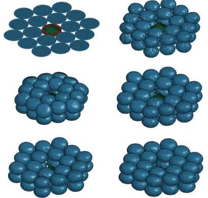
[image:3.612.328.507.185.317.2]Figure 2: LS-DYNA™ simulation of fully inflated array consisting of 38 cells.
The nonexistence of a single inflated volume is another advantage of the cellular approach compared to conventional inflatable structures. If one or several inflatable cells are deflated, the multiple cell array will ensure the integrity of the structure by adapting the surrounding cells. A hit of a micro meteoroid or space debris object would not automatically cause a failure of the entire structure13.
The structure is easily scalable to larger and smaller dimensions due to the cellular approach. Even the size of the single cell element can be varied. For this example the dimension of 14.5 cm as diameter is chosen so that the centre cell fits on a 10x10 cm2 box (diagonal ~14.5 cm) in order for the surrounding cells to be packed very closely. The initial design was based on the deployment of SAM from a cube satellite (10x10x10 cm3).
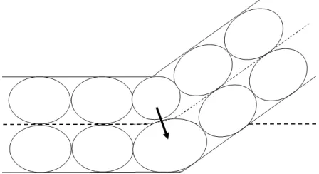
Figure 3: Schematic of shape changing principle.
IV.II Technology Demonstrator
In spring 2013, the experiment StrathSat-R14 will be launched onboard the sounding rocket REXUS13 from the Swedish space port ESRANGE. The REXUS (Rocket Experiments for University Students) programme is organised and funded by the German Aerospace Centre (DLR), the Swedish National Space
Board (SNSB) and the European Space Agency (ESA). The StrathSat-R experiment will eject two cube satellites at an altitude between 85 and 100 km. After ejection, the two cube satellites will deploy two different structures which both use the residual air inflation principle. One of the cube satellites will deploy a 36 cell smart structure with two actuator cells. The experiment has the purpose to prove the residual air deployment and the mechanical adaption of the bio-inspired shape changing concept. Cameras and Inertial Measurement Units (IMU) will capture the deployment and actuation behaviour during the mission. The obtained data will compared to on ground simulations and tests for further research into this concept.
[image:4.612.71.295.481.603.2]Figure 4: Triangular mass inflow for control volume method
The triangular mass inflow can be seen in Figure 4. By looking at the inflation time plots in Figure 5, Figure 6 and Figure 8, it is obvious that the full inflated volume is achieved after a fraction of the inflation time, while the pressure build up requires the length of the entire inflation process. The pressure increase is due to the defined triangular mass inflow, it needs to be verified if the actual pressure behaves the same way during the bench test.
V.I Single Cell
The single cell was modelled in LS-PrePost™ as a first simulation step. Two flat circular sheets with a diameter of 14.5 cm where placed over each other with a 1mm gap. The elements on the circumference where then joint to provide the enclosed volume required for the control volume method in LS-DYNA™.
Figure 5: Inflation of single cell (LS-DYNA™ simulation)
By using the equations outlined from Mladenov15, an uninflated diameter of the circular specimen of 14.5 cm, leads to a inflated diameter of 10.78 cm. With this calculation it can also be said that the thickness of the inflated ellipsoid will be in the order of 6.46 cm.
The single cell inflation was used to verify the concept of residual air inflation in the simulation and vacuum tests carried out at the University of Strathclyde. Due to the fact that the available vacuum chamber would only fit a few cells, simulations had to be run for multiple cells. Another issue for the vacuum chamber experiments or the ground test in general is that the structure is subjected to 1 g gravity. Especially for a low pressure, low stiffness structure, the influence of gravity can be major and falsifying the results of shape adaption experiments. For this reason a sounding rocket experiment outlined in Chapter IV.II is proposed. In the following the LS-DYNA™ simulation of this multiple cell array is outlined more in detail.
V.II Multiple Cells – from flat
An array of 18 elements in two rows was modelled for the first deployment simulation for multiple cells. In the beginning of the simulation, the cells were flat in the plane of the 1U cube satellite deployment box. Inflation time was chosen to be again one second, similar to the single cell simulation.
Figure 6: Deployment of inflating membrane (blue) out from flat case
[image:5.612.73.299.71.224.2] [image:5.612.323.528.332.527.2] [image:5.612.77.299.463.613.2]Figure 7: Radius of structure during inflation process from flat initial state
Figure 9 shows the variation of the radius of the 18 element structure over the inflation time. It can be observed that the radius starts with around 35 cm (70 cm diameter) and levels at around 27.5 cm after an initial bouncing movement over the first 0.5 seconds. Figure 2 also the inflated shape of a multiple cell simulation inflated from a flat original state. The membrane shown in Figure 2 has no deployment box; therefore 19 pairs of cells can be seen.
V.III Multiple Cell – from deployment box
For the second simulation of the multiple cell model, the membrane was compressed into the storage box that lies in the middle of the membrane. Rigid wall movement was used to compress the membrane before inflation.
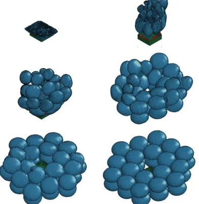
Figure 8: Deployment of inflating membrane (blue) out of constrained box (green)
The LS-DYNA deployment simulation can be seen in Figure 8. The first five frames are each 0.1 seconds apart while the sixth frame is captured after 3 seconds. The last frame shows that the structure is now the flat desired shape which is similar to the last frame in Figure 6. Figure 9 shows the radius of the membrane during packaging and inflation.
Figure 9: Radius of structure during packaging and inflation process from packaged initial state
In the first second, four rigid walls and one rigid wall from the top compress the structure into the deployment box. Inflation starts after the first second and also lasts for one second. Figure 9 shows that the initial radius is 35 cm which is leading to an inflated radius of 27.5 cm, the same result as the deployment simulation from the flat state. It can be seen that the obtained structure inherent the same shape regardless on the packaging method.
VI. SHAPE ADAPTION
[image:6.612.78.299.71.158.2]In the beginning, the shape changing abilities were modelled in LS-DYNA™ with changing the air pressure between two neighbouring cells. Limitation of the implementation of the shape control obtaining the desired shape led to the decision to write an own multi body dynamics code in Matlab. In this code every cell is modelled as a point mass in the centre of the inflating cell. The connections between the masses are modelled with springs which are able to take tension, compression and bending loads. Therefore every mass point has three degrees of freedom, two translatoric and one rotational. Currently, the structure is modelled for the two dimensional case but will be expanded to the three dimensional case soon. By changing to the three dimensional case, torsional stiffness will get added to the springs.
Figure 10: Drawing of multibody model for shape adaption simulation.
[image:6.612.316.543.82.170.2] [image:6.612.89.285.395.596.2] [image:6.612.328.534.539.624.2]two neighbouring cells of the bottom one apply a force to it. Whit this pressure change, the structure will bend itself downward. By introducing a control algorithm to this structure, the change towards a desired shape gets optimized. This is especially important when modelling in three dimensions or with more elements because the required change cannot be defined intuitively.
VII. ACKNOWLEDMENTS
We would like to thank the Physics Department of the University of Strathclyde for letting us use their vacuum chamber for our inflation tests. A big thank you goes to all the students involved in the StrathSat-R experiment that are working hard to get it ready for a launch onboard the REXUS sounding rocket in spring 2013. The authors would like the University Strathclyde providing the license to use LS-DYNA™ for the simulation of the Self-inflating Adaptive Membrane.
VIII. CONCLUSIONS
This paper shows that the Self-inflating Adaptive Membrane is a suitable alternative for large space structure. With its passive residual air inflation mechanism and the bio-inspired adaption technology, a simple deployable smart structure is created. The smart structure makes use of the pressure change between inflated cells with micro pumps which changes the global shape of the structure. This mechanism is beneficial compared to other adaptive structure because no power is needed to hold the structure in the desired shape. LS-DYNA™ inflation simulations of a single cell were presented that confirms the undertaken vacuum tests. The simulation was then expanded to the 36 element multi cell membrane. The two different deployment simulations, one from a flat, the other one from a box, showed similar results for the deployed membrane. This confirms that the developed membrane can obtain the desired shape, regardless of the packaging technique. The proposed sounding rocket experiment StrathSat-R which will launched onboard REXUS13 has the purpose to validate the 36 element multi cell simulation in LS-DYNA™. For the control and simulation of the shape adaption a multibody model is proposed that simplifies each cell as a point mass with bending, tension and torsion springs in between them. Future research will be focused to optimize the multibody code and to build a bench test model to validate the control algorithms.
REFERENCES 1
C. Mangenot, J. Santiago-Prowald, K. van't klooster, , N. Fonseca, L. Scolamiero, F. Coromina, P. Angeletti, M. Politano, C. Elia, D. Schmitt, M. Wittig, F. Heliere, M. Arcioni, M. Petrozzi, M. Such Taboada "ESA Document: Large Reflector Antenna Working Group - Final
Report," Technical Note
TEC-EEA/2010.595/CM. Vol. 1, 2010.
2
M. C. Bernasconi "Flexible-wall expandable structures for space applications: forty years of trying"," 1st European Workshop on Inflatable Space Structures, 21-22 May. Noordwijk, The Netherlands, 2002.
3L. Stiles, H. Schnaub “Electron Flux Deflection
Experiments with Coulomb Gossamer
Structures” AIAA-2012-1583, 13th AIAA Gossamer Systems Forum as part of 53rd Structures, Structural Dynamics, and Materials and Co-located Conferences, Honolulu, Hawaii, 23 - 26 April, 2012
4
M.Gärdsback, G. Tibert, D.Izzo: Design considerations and deployment simulations of spinning space webs. 48th AIAA/ASME/ASCE/AHS/ASC Structures, Structural Dynamics, and Materials Conference, Honolulu, HW, 23–26 April, 2007, AIAA-2007-1829.
5
T. Sinn, M. McRobb, A. Wujek, J. Skogby, f. Rogberg, J. Wang, M. Vasile, G. Tibert “Results of REXUS12’s Suaineadh Experiment: Deployment of a Web in Microgravity Conditions using Centrifugal Forces, IAC-12-A2.3.15, 63rd International Astronautical Congress, Naples, Italy, 1-5 October 2012.
6
S. Venneri, B. Wada "Overview of NASA's Adaptive Structures program," 44th International Astronautical Congress. Graz, Austria, 1993
7
H. Sawada, O. Mori, N. Okuizumi, Y. Shirasawa, Y. Miyazaki, M. C. Natori, S. Matunaga, H. Furuya, and H. Sakamoto: Mission Report on
the Solar Power Sail Deployment
Demonstration of IKAROS, AIAA 2011-1887,
presented at the 52nd
AIAA/ASME/ASCE/AHS/ASC Structures,
Structural Dynamics, and Material Conference, Denver, CO, USA, 4-7 April 2011
8
-2012-1518, 13th AIAA Gossamer Systems Forum as part of 53rd Structures, Structural Dynamics, and Materials and Co-located Conferences, Honolulu, Hawaii, 23 - 26 April, 2012
9
C. Galen "Sun Stalkers: How Flowers Follow The Sun", American Museum of Natural History, New York, NY, ETATS-UNIS, 1999, vol. 108, no5, pp. 49-51
10
E. B. Wilson, "The Heliotropism of Hydra", The American Naturalist , Vol. 25, No. 293 (May, 1891), pp. 413-433
11
G. Kiper, E. Soylemez "Deployable space structures." IEEE, 2009, pp. 131-138.
12
T. Sinn, M. Vasile, G. Tibert “Design and Development of Deployable Self-inflating Adaptive Membrane” AIAA-2012-1517, 13th
AIAA Gossamer Systems Forum as part of 53rd Structures, Structural Dynamics, and Materials and Co-located Conferences, Honolulu, Hawaii, 23 - 26 April, 2012
13
R. H. MacNeal “Meteoroid damage to filamentary structures”, National Aeronautics and Space Administration, 1967.
14
R. Clark, T. Sinn, C. Lücking, N. Donaldson, R. Brown, T. Parry, I. Dolan, C. Lowe, R. Bewick ”StrathSat-R: Deploying Inflatable CubeSat Structures in Microgravity”, IAC-12-E2.3.7, 63rd International Astronautical Congress, Naples, Italy, 1-5 October 2012
15