Journal of Energy and Power Engineering 7 (2013) 66-73
Investigating Two Configurations of a Heat Exchanger in
an Indirect Heating Integrated Collector Storage Solar
Water Heating System
Ruth Mossad and Marwaan AL-Khaffajy
Faculty of Engineering and Surveying, University of Southern Queensland, Toowoomba 4350, Australia
Received: April 11, 2012 / Accepted: June 18, 2012 / Published: January 31, 2013.
Abstract: Due to the environmental impact of energy usage and increased price of fusel fuel, consumers need to be encouraged to use renewable energy sources. The IHISSWHS (indirect heating integrated collector storage solar water heater system) is one of the most economical systems. It incorporates the collection of a solar energy component and a hot water storage component in one unit. The objective of this study was to investigate ways to enhance the thermal performance of the system. Two configurations of the system were studied: system with double row HX (heat exchanger) and tube length of 16.2 m, and system with single row HX and tube length of 8.1 m and 10.8 m. The service water tube inside diameter was also varied to 10.7 mm and 17.1 mm. The steady state continuity, momentum and energy equations were numerically solved, using FLUENT software. A standard k-ω turbulent model and surface-to-surface radiation model were used. The result showed that the system of 10.8 m tube length and single row HX provided higher outlet temperature than the system of 16.2 m and double row HX. Therefore, a significant reduction in cost and power usage can be achieved by using a single row HX.
Key words: Heat exchanger, FLUENT, solar collector, k-ω turbulent model.
1. Introduction
The increase in the price of fossil fuel and its negative environmental impact led to increased research involving cheap and clean sources of energy
such as solar energy. The use of solar energy has been growing in electricity generation, air conditioning and
water heating. An environmentally and economically important and costly use occurs in the production of domestic hot water. Water heater systems consume 14%
of the domestic energy consumption in the United States [1]. An economic and efficient system is
required to encourage households to use solar water heating systems.
Solar flat plate collectors are used for producing
domestic hot water. Integrated collectors are a type of
Corresponding author: Marwaan AL-Khaffajy, master of engineering, research fields: solar energy, turbulent flow simulation. E-mail: marwaan81@yahoo.com.
flat plate collector characterized by incorporating the
collection of the solar energy part and the storage of hot water in one unit [2]. This reduces the cost of the
system as there are no connection pipes and only a small area is needed for installation [3, 4]. There are two types of the integrated systems: the direct heating
system in which the service water flows into the storage tank and is directly heated through the collector
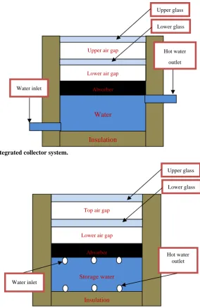
(Fig. 1) and the indirect heating system in which the service water passes through a serpentine tube immersed in the stored fluid (Fig. 2) [5]. Construction
of the storage tank in the direct heating type does not come cheaply. As the storage tank is connected directly
to town water pressure, the pressure inside the tank is relatively high. Therefore, the storage tank in this type needs to be manufactured from a high corrosion
resistant material that is able to withstand high pressures. This leads to increased construction costs as
D
Fig. 1 Direct heating integrated collector system.
Fig. 2 Indirect heating integrated collector system.
the cost of constructing the tank is more than 50% of the total system price [5].
Enhancing the heat transfer in the direct and indirect
integrated collector systems has been investigated quite widely. Ref. [2] used a corrugated absorber surface to
enhance the heat transfer between the absorber and the storage water in the direct heating system. Ref. [5] used a pump to circulate the storage water, in order to
enhance the heat transfer rate in the indirect heating system. Ref. [4] optimized the HX (heat exchanger)
positions relative to the tank wall, the service water tube length and diameter for the indirect heating system
with a circulating pump.
Reducing the heat loss from the system leads to improved performance of the system. Ref. [6]
investigated five strategies for reducing top heat loss. The 100 L tank capacity model and 1 m2 absorber area
was used to assess five cases: (1) single glass cover without night insulation; (2) single glass cover with night insulation cover; (3) double glass cover without
night insulation cover; (4) transparent insulation with single glass cover and (5) insulating baffle plate with
single glass cover. They found that case (3) provided the greatest thermal performance while case (5) had the
Lower air gap
Absorber
Storage water
Insulation Top air gap
Water inlet
Upper glass
Lower glass
Hot water outlet
Absorber
Water
Insulation
Upper air gap
Lower air gap
Water inlet
Hot water
outlet Upper glass
[image:2.595.151.436.89.528.2] [image:2.595.162.433.92.311.2]
lowest thermal efficiency. Ref. [7] studied the optimum top and lower air gap spacing in the integrated collector
system with double glass covers. They found that a combination of 15 mm for the lower gap and 35 mm for
the top gap gave the minimum radiation and convection heat losses.
The previous study in the indirect heating system [4, 5]
investigated the heat transfer between the storage and service water assuming that the initial condition of the
storage water is 60 oC or 80 oC. The present study will investigate the indirect heating system using different assumption. This study will investigate the collector
using the assumption that the temperature of the absorber surface is constant at 60 oC. This temperature
is based on an energy balance at the absorber surface assuming a solar intensity of 650 W/m2. Two designs of the HX have been investigated: double row HX with
service water tube length of 16.2 m and single row HX with tube length of 8.1 m and 10.8 m. Two flow rates of
the service water (500 L/h and 650 L/h) and two tubes inside diameters (10.7 mm and 17.1 mm) have been investigated. The goal of this work was to identify the
size of the pipe that gives the highest outlet temperature with the least energy usage.
2. Mathematical Model
In regards to the heat balance in the indirect heating
integrated collector storage solar water heater system, the absorber surface is heated from the solar radiation
which has been transmitted through the glass covers. During the daytime, the heat flows from the absorber to the storage and service water. When there is no solar
radiation, the energy in the storage water flows to the absorber and service water. In both cases, the absorber
loses some of the heat due to convection to the air in the lower gap, radiation to the lower-side walls (the side-wall surrounding the lower air gap spacing) and
radiation to the lower glass cover. The lower glass cover loses heat due to convection to the air in the top
gap and through radiation to the upper-side walls and to the top glass cover. The top glass cover loses heat due
to convection to the ambient air and due to radiation to the sky.
To predict the heat gained by the service water, the flow governing equations should be solved. According
to Ref. [8], the continuity, momentum and energy equation for steady, incompressible and turbulent flow can be written in abbreviated form as:
Eq. (1) is the continuity equation:
0 1
Eq. (2) is the momentum equation:
1
2
Eq. (3) is the energy equation:
3
where:
: Body force;
p: Fluid pressure;
: Fluid mean velocity component , , ; : Reynolds stress tensor;
: Cartesian coordinates (x, y, z); : Turbulent heat flux tensor; : Turbulent Prandtl number; υ: Fluid kinematic viscosity.
The above equations are non-linear partial differential equations and the analytical solution is
impossible except for very simple cases. However, these equations can be solved numerically. The
present study used FLUENT software that uses finite volume approach to solve the continuity, momentum and energy equations. The pressure-based type solver
was used. The effect of gravity was included considering full buoyancy effect. The variation of the
properties of air with temperature has been included by using incompressible ideal gas equation for estimating the density and kinetic theory equations for
specific heat, thermal conductivity and viscosity. The variation of the properties of water such as density, ρ,
included using Eqs. (4)-(7), respectively, which were recommended by Ref. [9].
1.3187 10 1.8447 10
9.9428 10 23.28
1113.5 4
3.533 10 4.8141 10 2.4637
10 0.0056188
0.48281 5
3.321729 10 4.459811 10
2.248733 5.041488 10 4.654524
10 6
6.2068 10 8.0897 10
3.8437 10 7.7569 10
6.1019 7
The standard k-ω turbulence model has been used because the model has been tested by Gertzos et al. Ref.
[5] and there was a good agreement between their experimental results and numerical ones. The
velocity-pressure coupling was treated by using the SIMPLE algorithm and a first order upwind scheme for
momentum, turbulent kinetic energy and turbulence
dissipation. For the residual, 10-4 was used as a convergence criterion for all terms: x-velocity, y-velocity,
z-velocity, kinetic energy, epsilon and continuity, except for the energy, which was taken as 10-8.
3. Computational Fluid Dynamic Simulation
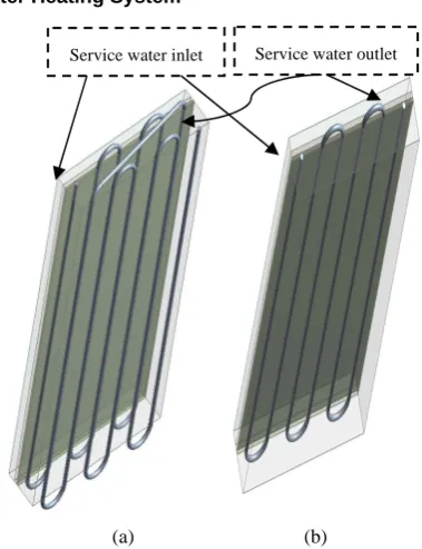
Steady 3D CFD models for two different configurations of the indirect heating integrated
collector system (Figs. 3a and 3b) have been developed to evaluate the heat gained by the service water. One has a double row HX; the other has a single row HX.
For both models, two types of copper tube were used for the service water: tube type A DN 15 (1/2) with
inside diameter of 10.7 mm and wall thickness of 1 mm, and tube type B DN 20 (3/4) with inside diameter of 17.1 mm and wall thickness of 1 mm. The effective
(a) (b)
Fig. 3 (a) Indirect heating system with double row HX; (b) indirect heating system with single row HX.
length (tube inside the collector) for the tube in the system of double raw HX was 16.2 m, and of single
raw HX was chosen as 8.1 m and 10.8 m.
The boundary conditions on the top-glass cover was taken as convection with a heat transfer coefficient of
10 W/(m2K) to an ambient temperature, Ta, of 290 K and radiation to the sky at a temperature which was
taken according to Ref. [10] as 0.0552 Ta1.5. A constant temperature of 333 K was assumed for the absorber surface in all cases. A velocity-inlet with 290 K
temperature was assumed for the service water at inlet and pressure-outlet was chosen at the service water
outlet. The collector angle was chosen to be at 45o. For both models, the inner dimensions of the storage tank were as 81 cm × 135 cm × 10 cm containing about 109
L of water. The side and lower walls of the collector was assumed to be adiabatic. The absorber was made of
M-N-C (metallic-nickel chrome) with 10 mm thickness. The thickness of the lower and top glass cover was taken as 3 mm. The top and lower air gap spacing was
taken as 35 mm and 15 mm, respectively, because they were found to be the most efficient combination [7].
The physical properties adopted in the simulation of these materials are given in Table 1.
[image:4.595.329.519.74.321.2]
Table 1 Physical properties of the materials used.
Material ρ (kg/m3) Cp (J/(kg·K))
K (W/(m2K))
є
emissivity
M-N-C 7,865 460 19 0.94
Glass 2,800 800 0.81 0.93
Copper 8,978 381 387.6 Not included The geometry and computational grid were generated using ANSYS 13.0 software. To validate the
grid dependency, three computational grids have been developed for the model with double row HX: 2.5
million, 2.74 million and 3.125 million elements. The
results of all three models were almost the same, but the model of 2.74 million elements was converged
faster than the others because the mesh quality was better. The researchers adopted the same way to
generate the computational grid in the model of 2.74
million for all other models.
Radiation between surfaces (absorber, lower glass
and top glass) has been considered, using a
surface-to-surface radiation model, ignoring the effect
of the medium between the surfaces. The radiation
process was started by estimating the view factors
between the surfaces. The radiosity of the surfaces
have been updated every 10 iterations (FLUENT
default) throughout the solution, based on the new surfaces’ temperature. This is to include the heat
transfer due to radiation from these surfaces more
accurately.
4. Results and Discussion
For each collector configuration, tube types A and type B were used. For each case, two service water
flow rates were examined: 500 L/h and 650 L/h. Service water temperature at inlet was taken as 17 oC. Flow with four values of Reynolds number (Re) were investigated, for tube A (Di = 10.7 mm): Re = 2.28 × 10⁴ and 2.96 × 10⁴ and for tube B (Di = 17.1 mm): Re = 1.42 × 10⁴ and 1.85 × 10⁴. The length of the tube was 16.2 m for the double row HX, 8.1 m and 10.8 m for the single row HX.
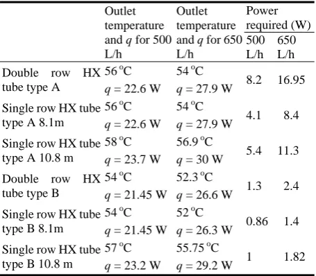
The outlet temperatures, heat gained by the service water (q) and the power required to run the system of
all cases are presented in Table 2. The higher flow rate enhanced the heat exchanged since more heat transfer
took place; however, the outlet temperature was less than that for the lower flow rate cases, which is
expected. As expected, the longer length for the single row pipe produced higher outlet temperature. The power required to run the system with 8.1 m tube
length for both tube A and B was half of the power required for the system with 16.2 m, while the outlet
temperature was the same. Therefore, the back row of the tubes was not effective.
The temperature contours of the service water for the
double row HX tube type A are presented in Fig. 4a. The temperature of the service water increased only in
the front row of the HX and there was not much increase in the temperature in the back row. This behavior was the same when type B of the tube was
investigated (Fig. 4b). This was also the case for both mass flow rates. This can confirm that the back row of
the tube is not effective.
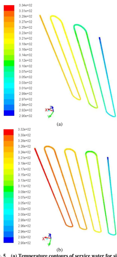
Figs. 5a and 5b present the temperature contours of the service water for the single row HX, tube type A,
with flow rate of 500 L/h and for tube length 8.1 m and 10.8 m, respectively. Most of the service water tube
[image:5.595.59.286.102.163.2]was effective because there was an increase in the temperature along the tube.
Table 2 Outlet temperature, heat gained by the service water (q) and power required to run the system for all studied cases.
Outlet temperature and q for 500 L/h
Outlet temperature and q for 650 L/h Power required (W) 500 L/h 650 L/h Double row HX
tube type A
56oC 54 oC
8.2 16.95 q = 22.6 W q = 27.9 W
Single row HX tube type A 8.1m
56oC 54 oC
4.1 8.4 q = 22.6 W q = 27.9 W
Single row HX tube type A 10.8 m
58oC 56.9 oC
5.4 11.3 q = 23.7 W q = 30 W
Double row HX tube type B
54oC 52.3 oC
1.3 2.4 q = 21.45 W q = 26.6 W
Single row HX tube type B 8.1m
54oC 52 oC
0.86 1.4 q = 21.45 W q = 26.3 W
Single row HX tube type B 10.8 m
57oC 55.75 oC
[image:5.595.310.538.534.733.2]
(a)
(b)
Fig. 4 (a) Temperature contours of service water for double row HX, with tube A and flow rate 500 L/h; (b) temperature contours of service water for double row HX, with tube B and flow rate 500 L/h.
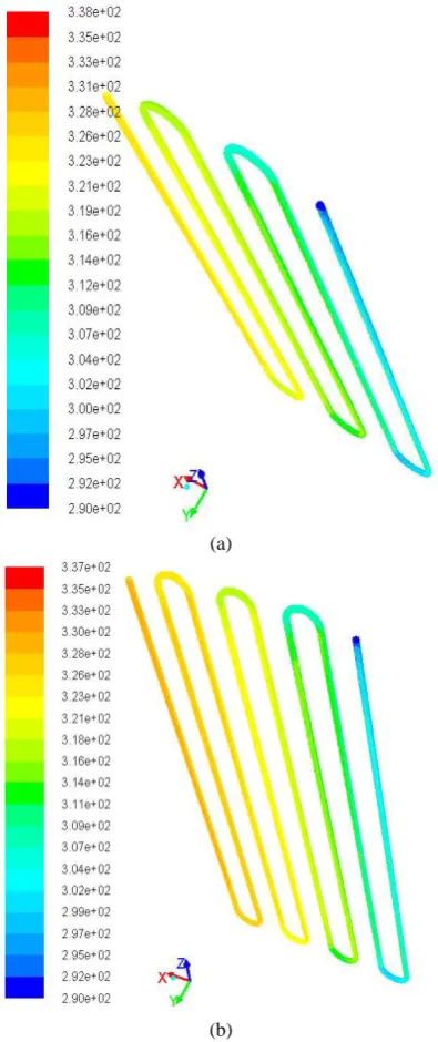
The temperature contours for the single tube HX, tube type B, with 650 L/h flow rate and tube length of
8.1 m and 10.8 m are presented in Figs. 6a and 6b, respectively. It is obvious that the outlet temperature increased to 57 oC versus 54 oC in the 8.1 m. The
temperature difference between the absorber and the outlet service water was around 6 °C at exit. This
indicates that there is no need for further increase in the tube length according to the recommendations in Ref. [11].
(a)
(b)
Fig. 5 (a) Temperature contours of service water for single row HX, tube A, length 8.1 m and flow rate 500 L/h; (b) temperature contours of service water for single row HX, tube A, length 10.8 m and flow rate 500 L/h.
For the single row HX, it was obvious that the longer the time exist, the higher heat the pipe gains, hence, the higher outlet temperature is. Increasing the flow rate,
which increased the Reynolds number, increased the heat gain. However, as the flow rate was high, the
outlet temperature was low which is expected.
The system of tube type A with tube length of 10.8 m gave the highest outlet temperature which was 58 oC,
[image:6.595.320.523.83.527.2] [image:6.595.70.272.83.523.2]
(a)
(b)
Fig. 6 (a) Temperature contours of service water for single row HX, tube B, length 8.1 m and flow rate 650 L/h; (b) temperature contours of service water for single row HX, tube B, length 10.8 m and flow rate 650 L/h.
system of tube B was much lower than the system of
tube A for the same length. This was expected because the power depends on the square of the average velocity in the tubes, which was lower for tube B. This
has an advantage of reducing the running cost of the system with very little sacrifice of the final outlet
temperature.
The outlet temperature of the service water, the required flow rate, the power needed to run the system
as well as the cost of the system should be considered in choosing the optimum HX configuration for a
household user. However, this research highlighted that the double row HX proved not to be a good design for both size tubes considered in this work, because of
the high cost and high pumping power required with no additional benefits than the single row HX.
5. Conclusions
The power required to run the system and the initial
cost can be reduced by using a single row HX rather than a double row HX. For the single row HX, the larger
pipe (type B) needed power almost five times lower than the smaller pipe (type A). Although the initial cost of type B pipe may be slightly higher than type A, the
savings in the running cost is justified with very little reduction in the final outlet temperature. After all, the
main objective of using the solar heater is to reduce the human impact on the environment, so reducing the energy needed to run the solar system is justified.
Acknowledgments
The authors would like to acknowledge University of Southern Queensland for providing ANSYS 13.0 software and a HP (high performance) computer to
finalize this research.
References
[1] Where Does My Money Go?, Department of Energy US, 2010.
[2] R. Kumar, M.A. Rosen, Thermal performance of integrated collector storage solar water heater with corrugated absorber surface, Applied Thermal Engineering 30 (13) (2010) 1764-1768.
[3] A.J.N. Khalifa, R.A. Abdul Jabbar, Conventional versus storage domestic solar hot water systems: A comparative performance study, Energy Conversion and Management 51 (2) (2010) 265-270.
[image:7.595.72.270.84.555.2]
storage solar water heaters (ICSSWH), Renewable Energy 35 (8) (2010) 1741-1750.
[5] K.P. Gertzos, Y.G. Caouris, Experimental and computational study of the developed flow field in a flat plate integrated collector storage (ICS) solar device with recirculation, Experimental Thermal and Fluid Science 31 (2007) 1133-1145.
[6] R. Kumar, M.A. Rosen, Comparative performance investigation of integrated collector-storage solar water heaters with various heat loss reduction strategies, International Journal of Energy Research 35 (2010) 1179-1187.
[7] M. AL-Khaffajy, R. Mossad, Optimization of the air gap spacing in a solar water heater with double glass cover, in: 9th Ausralasian Heat and Mass Transfer Conference, Melbourne, Vectoria, Australia, 2011.
[8] M. Raisee, S.H. Hejazi, Application of linear and non-linear low-Re k-[epsilon] models in two-dimensional
predictions of convective heat transfer in passages with sudden contractions, International Journal of Heat and Fluid Flow 28 (2007) 429-440.
[9] K.P. Gertzos, S.E. Pnevmatikakis, Y.G. Caouris, Experimental and numerical study of heat transfer phenomena, inside a flat-plate integrated collector storage solar water heater (ICSSWH), with indirect heat withdrawal, Energy Conversion and Management 49 (2008) 3104-3115.
[10] N. Akhtar, S.C. Mullick, Computation of glass-cover temperatures and top heat loss coefficient of flat-plate solar collectors with double glazing, Energy 32 (2007) 1067-1074.