Modeling and Experiments for
a
Class of
Robotic Endoscopes
Thesis by
Andrew Brett Slatkin
In Partial Fulfillment of the Requirements for the Degree of
Doctor of Philosophy
California Institute of Technology Pasadena, California
@ 1999 Andrew Brett Slatkin
Acknowledgements
This dissertation would not exist if not for the support, guidance and love of a
special group of people who will always have nly deepest apprecia;tion.
Professor Joel Burdick, my academic advisor, liberally offered his technical, fi- nnncial and emotional support. I have been extremely fortunate for the opportunity to have worked with this generous man. Whether he realizes it or not, his actions and reactions helped to guide me from "wandering the desert."
VVarren Grundfest, M.D., the Director of the Laser LaboraZlory at Cedars-Sinai Medical Center, has been my advisor within the medical field ES well as a member of
my Thesis Committee. Without his active support of this work, it would never have proceeded. Warren has always demonstrated a tremendous capacity to envision new medical technology, and his boundless energy and enthusiasm are contagious.
I also wish to recognize the other members of my Thesis Committee. Professors Richard Murray and Erik Antonsson dramatically improved the quality of this dis- sertation with their reviews of early drafts. And I cannot thank Professor James Knowles enough for his consistent support during my stay at Caltech. I consider myself extremely lucky that Jim Knowles was there: at my "mini orals," during five terms of coursework, at my Candidacy Exams, as a reviewer of my thesis work, and whenever I dropped in on him with a question or problem. He has always shown genuine concern for me (and for all of his students).
chine Shop. I will always look back happily on the time (years) I spent in their shop. Also, they are consistently valuable design and manufacturing consultants, and other Caltech experimenters should take full advantage of their expertise,
I wish to thank the Cedars-Sinai Medical Center staff and researchers: Carol Ruppe, Thanassis Papaioannou, Ramez Shehada, Laurie Zelby) Linda Whisenhunt and Evelyn Berkowitz. I would not have enjoyed the process or results of my animal experiments without their technical and administrative efforts (and their big hearts). My love and appreciation of my farnily and friends must also be voiced. I cannot find words strong enough to express my feelings of appreciation for my parents. Fortunately, they already know how I feel. To Denise, without whom my work at Caltech would never have begun, I know that the pursuit of this degree has been very hard on her. And I wish her peace, love, and happiness, always. To Carol, who has supplied unlimited practical, moral and psychological support. To my daughter, Alexandra, who has been amazingly patient. She puts my life in focus and gives it meaning. To my grandparents, Naomi and David, who have always supported and challenged me t o stretch toward goals that appeared out of reach. To Bob, Linda and Mel, I couldn't have asked for better in-laws during these trying times. To Renny, Lisa, Andy, and Kelly who knew better than to ask when I'd be done (but were always dying to), their loving thoughts and actions will always be remembered. And to the rest of my family and old friends whose love and empathy have made all my struggles easier to bear (they should expect to see a lot more of me from now on).
My thanks and love to Anna (I cannot count the ways in which she helped make this thesis a reality) and to Richard Weintraub (his insights over recent years have shaped my life and work - none of this would exist without him).
v
Modeling and Experiments for a Class of Robotic
Endoscopes
by
Andrew
Brett Slatkin
In Partial Fulfillment of the
Requirements for the Degree of
Doctor of Philosophy
Abstract
Current developments in minimally invasive medical practice motivated this
study of self-propelled, robotic endoscopes for deep penetration into curved
physiological lumens. The conceptual design of such devices is applicable to
endoscopy within a variety of lumens in the human body, e.g., blood vessels,
but the initial objective of this technology is to provide access to the interior
of the entire small intestine without surgical incisions. The small intestine
presents several challenges to endoscopic penetration: it is extremely compli-
ant to applied loading, internally lubricated, easily inj wed, and contains many
tight curves along its length of approximately eighteen feet.
This thesis reports the basic design and locomotion concepts for one class of
endoscopic robots that are intended to provide safe and reliable traversal of the
small intestirle via worm-like actuation. Five generations of proof-of-concept
prototype robots have been built to validate the fundamental concepts. Fur-
t hermore, these miniaturized robots have incorporated the following features:
tubing, the small intestines of deceased pigs, and in the small intestines of live,
anaest hetized pigs.
At the onset of this research, little regarding the elastic properties of small
intestine existed in the biomechanics literature that would be applicable to
the design of these mechanisms. However, accurate prediction of the small in-
testine's response to robotic loadings would dramatically improve the research
and development process of these machines. Thus, an investigation of the
elastic behavior of the small intestine commenced. Finite defamation, non-
linear, anisotropic, incompressible, viscoelast ic behavior of the small intestine
was studied. This soft tissue biomechanical analysis and experimentation (on
living and dissected intestinal specimens) culminated with a numerical model
that simulates intestinal response to the actions of a prototypical robotic com-
ponent. Experiments on living specimens were performed to determine the
levels of applied loadings and internal stresses that are likely to injure these
fragile tissues, and the biomechanics computer modeling incorporates three
vii
Contents
I Introduction. 1
. . .
1.1 Motivation for Robotic Endoscopy 1
. . .
1.2 A Brief Synopsis of this Thesis 4
2 Medical Technology 8
. . .
2.1 Endoscopy Primer and Current Practice 8
. . .
2.2 Robotic Medical Technology 11
3 The Robotic Endoscope 17
. . .
3.1 System Overview 19
. . .
3.2 Methods for Locomotion 27
. . . .
3.2.1 The Gait of a 2-Gripperil-Extensor Mechanism 28
3.2.2 Some Gaits for a 3-Gripper/2-Extensor Mechanism
. .
303.2.3 Gaits for Designs with Numerous Grippers and Extensors 34
. . .
3.3 Prototype Component Designs 35
. . .
3.3.1 Traction Segment Designs 37
. . .
3 3 . 2 Extensor Segment Designs 40
. . .
3.3.3 Valve Designs 42
. . .
3.4 Elec~ronie Controls 45
. . .
4.4.5 Criteria for Excessive Loading of the Intestines
. . .
1254.5 Elasticity Experiments of the Small Intestine . . . 128
4.5.1 Experimental Goals and Issues
. . .
1284.5.2 Experimental Apparatus
. . .
1304.5.3 In Vivo Biomechanics Experiments
. . .
1354.5.4 In Vzvo Experiment a1 Observations
. . .
1414.5.5 in f i t r o Biomechanics Experiments
. . .
146. . . 4.5.6 in Vitro Experiment a1 Observations 147
. . .
4.6 Biomechanics Results 149. . .
4.6.1 Data Reduction for Modeling 149. . .
4.6.2 Discussion of the Experimental Results 158 4.6.3 Quasistatic Model of the Gripper-Intestine Interaction 160 5 Conclusions and Recommendations for Future Work 170. . .
5.1 The Problem Revisited 170 5.2 Significant Results of This Research. . .
1715.2.1 The Robotic Endoscope System Design
. . .
172. . .
List of
Figures
3.1 Schematic overview of a prototypical robotic endoscope system. 19
3.2 Photographs of a fourth generation, prototype, robotic endo-
scope consisting of three grippers and two extensors.
. . . . .
213.3 Schematic diagram of the robotic endoscope.
. . .
.
. . . . . .
253.4 Schematic diagram of locomotion for a 2-Gripper/ l-Extensor
Mechanism. . . . . .
.
..
.. . . . . . . . . . . .
..
. . . ..
29 3.5 Schematic diagram of a traveling wave-like gait for a 3-gripperl2-extensor mechanism.
. . . . . . . . . . . . . .
.
. . .
. .
. . .
313.6 Schematic diagram of locomotion for a 3-gripper/2-extensor
mechanism. .
.
.. . . . .
. . ..
..
. . . . ..
. ..
. .. .
. 333.7 Schematic diagrams of additional locomotion gaits for a 3-gripper/2-
extemor mechanism.
. . . . .
.
. . . .
.. . . .
..
. . . .
343.8 Schematic diagram of wave-like locomotion for a 5-gripper/4- extensor mechanism.
. . . . . .
.. .
.. .
. . . ..
. . . . 363.9 Schematic section view of a traction segment.
.
. .. .
.. . .
383.10 Schematic section view of a Generation Five extensor segment
assembly. .
.
.. . .
.. . . . . . . .
.. . . . . . . .
41 3.11A
silicon, micromachined valve installed in the test fixture.. .
433.13 A photograph of two prototype robots (Generation One above, Generation Two below).
.
. . . . . . . . .
.. . .
.. . .
. ..
51 3.14 A Generation Two prototype crawling through a urethane tube. 51 3.15 A Generation Four device is tested in urethane tubing. . . . . 52 3.16 A Generation Four, 3-gripper/2-extensor robot negotiates a loop. 53 3.17 A Generation Four prototype robot approaches a simulatedpolyp within the urethane tube.
. . . .
. . . . . ..
..
. . 54 3.18 The first Generation Five prototype robot.. . . . .
553.19 A prototype robot (Generation Four) is inserted into the small intestine of a live pig.
. . .
.
.
.. . .
.. .
. . . .. . .
. .. .
58 3.20 One of the robot's gripper segments is inflated (Generation Four). 583.2 1 Schematic sect ion view of a miniat me, normally closed, solenoid
valve: the Teflon conical plunger face seals against the cham-
fered aluminum valve seat.
. . . .
.
.
.
. . . .
.
.
.. .
.. . .
64 3.22 Photograph of a completed valve assembly surrounded by vari-ous parts and subassemblies.
. . . . . . .
.. .
. . . . 65 3.23 Photograph depicting the three solenoid valves used in thisproject (Left: the off-board valve of Generations One, Two and
Three; Center: Generation Four; Right: Generation Five).
. .
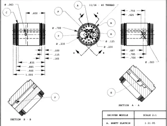
663.24 The machinable glass-mica) ceramic substructure for the Gen-
eration Five gripper module. This single part serves in place of
a complex assembly in Generation Four.
.
. . . .. .
. . ..
. 76 3.25 Robotic endoscope taxonomy. ..
.. .
. . ..
..
. . . . 84 3.26 Table of the features of the five generations of prototype robots. 874.2 Deformat ion as viewed in principal axes.
. . .
.. . .
. . .. .
9 1 4.3 Reference frames for analysis of axisymmetric, thin walled bodies. 934.4 Derivation of stresses acting on an element.
.
. . .. . . .
. ..
94 4.5 Pressure vessel analysis.. . . .
.
.
.
. . . .
..
.. . . .
..
. 1 12 4.6 Geometry for analysis of the "incompressible" kinematic con-straint.. .
.
..
. . ..
. . . .. .
. .. .
.. . . . . .
. . . 1144.7 The simplified modeling of the experimental specimens.
. . . .
116 4.8A
"free body" element for the derivation of the shearing tractiondistribution.
. .
.
. . . . . . . .
.
.
. .
.
.
. . . .
.
. . .
..
. 121 4.9 A close-up schematic of the test fixture..
. . . .. .
. .. .
131 4.10 No experimental boundary conditions can prevent axial tensionin the test specimen.
. . . . . . . . . . . .
. . . . ..
..
.. .
131 4.11 An intestinal specimen is prepared for testing.. . . . . . .
1354.12 An intestinal specimen is inflated to a low internal pressure.
.
1364.13 Blood flow has been visibly constricted in many vessels.
. . . .
1364.14 With increased internal loading, the intestinal specimen is sub-
st ant ially injured. Essentially, all its blood has been squeezed
out.
.
. . . . . . . . . . . . . . .. . . . .
..
. .. .
. . ..
. 137 4.15 Injury is apparent by: the numerous dots of hemorrhage evidentin the membrane and visibly constricted blood vessels. Stress
relieving cuts between blood vessels in the mesentery are visible
beneath the tubular segment. . .
. . . . .
. . .. .
.. .
. . . 138 4.16 The in vivo mewwements of intestinal diameter as a functionof internal pressure.
. . . . .
..
.. .
. . . 142 4.17 The in vivo measurements of length of an intestinal segment as4.18 The in vitro memurements of intestinal diameter as a function
of internal pressure.
. . . . . . . . . . . . . .
. .
. . . . .
.. .
148 4.19 Raw creep data : all in vitro trials. ..
. ..
. ..
. . . 150 4.20 Raw creep data ( : all in vitro trials..
.
. . . . . .
.. .
150 4.21 Circumferential (OD) strain versus pressure for 17 in vivo trials. 151 4.22 Axial/meridional strain versus pressure for 17 in vivo trials. . 152 4.23 The anisotropic constitutive relations for intestines, specifically:a;, = g m ( ~ ,
+
VE, E~+
YE,).. . .
..
. .. .
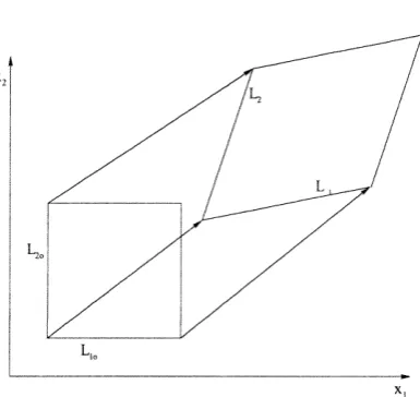
1564.24 Circumferential (OD) strain versus pressure for 19 in vitro trials. 157 4.25 The unstressed reference configuration and the deformed con-
figuration of the simulated intestinal segment.
. . . .
.
. . .
.
16 14.26 The flow chart for the numerical simulation of the intestinal
reactions of an expanding gripper segment.
.
.
. .
.. .
..
.
.
162 4.27 A graphical represent at ion of the iterative process convergingtoward the zero traction contiguration of the first length element
of the intestinal segment.
. . . . . . . . . . . .
.. . .
163 4.28 A graphical representation of the iterative process convergingtoward the zero traction configuration of the second length el-
ement of the intestinal segment.
. . . . . . .
.. . .
. .. .
164 4.29 Animation of gripper-intestine modeling. The grayscale reflectsrelative impact of the loading (white = danger). Left
Chapter
1
Introduction
1.1
Motivation for Robotic Endoscopy
This dissertation considers issues that are essential to the development of a
gastrointestinal robot or robotic endoscope for traversing the human gastroin-
testinal system. Such a device could provide minimally invasive access to
large sections of the gastrointestinal system which are currently accessible
only through invasive methods. Minimally invasive medical practice utilizes
slender instruments inserted through naturally occurring or surgically pro-
duced orifices into interior body cavities for the visualization, diagnosis, and
therapeutic intervention of injury and disease. These techniques are aimed
at reducing the amount of peripheral tissue which must be damaged in order
to reach the surgical site. Minimizing such collateral damage can reduce pa-
tient recovery time and postoperative discomfort. Furthermore, potential for
deleterious side effects, e .g., keloid development, can be diminished.
Because of these potential advantages, one of the biggest trends in med-
traditional open surgery (i.e., invasive procedures) [59]. Arthroscopic joint
surgery, colonoscopic polypect omy removal of growths from the colon
laparoscopic gall bladder removal are widely recognized examples of this trend.
In addition to improvements in patient care, there are tremendous economic
incentives for the adoption of these techniques. As reported by the Wilkerson
Group in 1992, approximately 2 1 million surgical procedures are performed each year in the United States with approximately 1 million performed
in a minimally invasive manner. They further estimated that potentially 8
of the 21 million surgeries could have been performed in a minimally inva-
sive manner. Since minimally invasive approaches tend to reduce the duration
of post operative hospitalization, increased use of these techniques would be
expected to result in dramatic savings in hospital residency costs and lost
patient wages 591.
A
major technological impediment to increasing usage ofminimally invasive approaches is lack of minimally invasive access to interior
body cavities. While the primary focus of this thesis is to provide minimally
invasive access to the gastrointestinal system, we hope that successful deploy-
ment of this technology will pave the way for other applications of robotic
technology to minimally invasive medicine.
Conventional endoscopes provide minimally invasive visualization of inte-
rior ducts and cavities, such as the stomach, colon, urinary tract and res-
piratory tract. The term endoscope literally means "inner scope;" thus, an
endoscope is merely a tool which provides visual access to the body's interior.
Flexible endoscopes use fiber optic bundles or distal CCD chip cameras to transmit an optical image from within the body. Fiber optic bundles can also
act as a conduit for laser surgery, i.e., cutting, cauterizing, and/or vaporizing
for steering their distal tips, and their larger size can permit the deployment of
simple surgical instruments for manipulation and dissect ion of tissue. These
instruments are currently inserted without incisions into a variety of phys-
iological lumens (tube-like structures and cavities such as: the esophagus,
stomach, colon, urinary tract, respiratory tract, nasal sinuses, seminal ducts,
tear ducts, etc. Additionally, with surgical incisions, several other lumens and
cavities can be accessed, e.g. the small intestine, the bile ducts, the cranium,
and blood vessels.
Gastrointestinal endoscopy focuses on the diagnosis and treatment of dis-
eases of the alimentary canal (mouth, esophagus, stomach, small intestine,
colon, rectum, and anus) by the use of flexible endoscopes. Gastroscopes are
used to visualize the inner surfaces of the stomach and colonoscopes provide
visualization of the large intestine, or colon. Together, these two ends of the
alimentary canal represent only thirty percent of the length of the gastrointesti-
nal tract. The remaining seventy percent, also known as the small intestine,
cannot be reached using current endoscopic technology without abdominal in-
cisions. Since the small intestine repeatedly traverses the abdominal cavity,
locating a specific disease site within it can require open surgery (laparotomy).
Recent estimates from the Journal of Clinical Gastroenterology (1992) indi-
cate that diseases of the small intestine, such as Crohn's disease, ulcerative
colitis, and intestinal blockage, afflict approximately 430,000 people annually
in the United States. At present, the diagnosis of diseases of the small intestine
is done either by assessing the "external" symptoms, often with radiological
subst ant iation e.g., via barium ingestion, MRI, or ultrasound imaging
invasive surgical exploration. In many instances, the current therapy requires
4
1.2
A
Brief Synopsis of this Thesis
This dissertation reports efforts to develop a robotic endoscope that can di-
rectly access and visualize, without incisions, the entire gastrointestinal tract.
The long term goals of these efforts are to produce a physician-guided robot
that can be inserted though the mouth or anus, positioned at an entrance to
the small intestine using a modified, conventional endoscope, and then com-
manded to locomote through the small bowel to perform medical diagnostic
procedures. Such a device would provide an alternative to the highly invasive
diagnostic methods described above. A follow-on goal is to supply therapeutic intervention when possible. For example, the robot may assist in the removal
of blockages, excise diseased tissue and perform biopsies, or precisely deliver
anti-idammatory drugs for non-invasive treatment of Crohn's disease. In or-
der to satisfy medical needs such as these, the first step is to develop a robotic
endoscope that can dependably travel through the small intestine. Hence, the
first half of this dissertation develops a robotic locomotion concept and de-
scribes its prototype implementations and subsystems. Additionally, it was
recognized early that a thorough understanding of the geometry, elastic be-
havior, surface texture and lubricity of the small intestine would be critical
to the success of this endeavor. To that end, qualitative and quantitative
surgical experiments were performed on anesthetized pigs. The quantitative
investigation into the elasticity of pigs' small intestines in vivo was repeated
for excised specimens in vitro. From the experimental data, a simplified model
for the mechanical behavior of small intestines wa,s created to be a design tool
for future robotic endoscopy efforts.
current state of the art in endoscopy is introduced, and limitations of the
existing technology are discussed. Lastly, this chapter touches on a variety
of advancing developments in surgical technology that have resulted from the
application of robotics and computers.
Chapter 3 proposes a robotic endoscope design concept intended to over- come current endoscopic limitations that prohibit complete access to the small
intestine without surgical incisions. Conceptual locomotion modalities for
these devices are then presented. And in order to evaluate these concepts,
five generations of proof-of-concept prototype endoscopic robots have been
designed, built and tested. After a general overview of the proposed robotic
system, complete with descriptions of the various subcomponents and their
evolution, the final, fifth generation prototype is introduced. For historical
purposes, this chapter ends with an overview of the evolution of the five gen-
erations of prototype systems. In t his concluding section, t he salient features
and functional performance of these robots are compared and contrasted.
Chapter 4 reports on efforts to accelerate the design process for these med-
ical instruments via investigation into modeling of the mechanical behavior of
the small intestine. This chapter opens with an introductory section cover-
ing basic concepts of solid mechanics and mathematical elasticity. The next
two sections address the specific problems and issues of soft tissue biomechan-
ics. The balance of the chapter reflects original analytical, experimental and
numerical research into modeling the elastic behavior of the small intestine.
Chapter 5, in conclusion, revisits: the medical motivation for the endo-
scopic access of the small intestine without surgical incisions; the robotic s y s
viable locomotion of robotic endoscopes for the small intestine.
When this research commenced, little relevant "prior work" existed in the
literature. The novelty of this technology has justified the issuance of two
United States Patents 5337732 and 5662587 . Forging into uncharted territory, this research path has been circuitous. Many initial forays into
a forest of previously unasked questions, unanticipated design problems and
modeling issues ended abruptly before yielding useful and reportable results.
Continuing with this metaphor, it is hoped that this thesis can serve as a
preliminary "trail map" for future endeavors into self-propelled endoscopy.
The original contributions of this work are highlighted below.
Fundamental design concepts and morphologies of a self-propelled endo-
scope that could overcome the limitations of current medical technology were
investigated .
a An original locomot ion methodology was developed, and five generations
of endoscopic robot prototypes were designed, fabricated and tested.
a Biomechanics experiments were performed to study the biaxial, "whole
organ" behavior of the small intestine; this approach is in contrast to the typ-
ically reported uniaxial tensile tests of dissected strips of excised tissue. The
experimental apparatus was developed for use on tubular segments of both
living and dead small intestines.
*
The biomechanics experiments compare the material behavior of both liv-ing and dissected intestine in order to determine if and when the dead tissue
provides useful data. Since experiments on dissected tissues are substantially
less expensive and complicated the experiments on living intestines require surgical incisions into animials that are fully anaesthetized these results may
a The experimental study of the biaxial elastic behavior of living intestine
was crucial in identifying the loads and stresses that would potentially cause
injury to the fragile intestinal tissues.
A
study of excised tissues cannot de-termine the loading (or stressing that corresponds to the onset of injury of
living specimens.
With experimentally gathered data, a model of small intestinal behav-
ior was developed to act as a tool for future endoscopic robot design efforts.
Additionally, this modeling may assist in the design and analysis of other gas-
trointestinal surgical instruments as well, e.g., innerluminal intestinal staplers
that radially load the intestine during anastomosis.
The biomechanics model was incorporated into a numerical simulation
that predicts the imposed loading, internal stress, and "injury potential" that
Chapter
2
Medica
Technology
After describing the current st ate of relevant medical technology, this chap-
ter illustrates engineering efforts to introduce advanced technologies into the
practice of health care.
2.1
Endoscopy Primer and Current Practice
As previously mentioned, endoscopy refers to the use of medical instruments to
view the interior of the human body. There are innumerable anatomical sites
for which such visualization is desired; one could argue that almost all medi-
cal subspecialties could benefit from devices which provide minimally invasive
visualization. Currently, each of the following specializations benefit from
endoscopy: Otolaryngology, Orthopaedics, Cardiology/Cardiac Surgery, Pul-
monary surgery, Oncology, General Surgery, Neurology/Neurosurgery> Proc- tology, Gastroenterology, Urology and Gynecology. In order to look into each of these different regions of the body, highly specialized devices and procedures are typically developed. Additionally, if possible, these instruments should be
refer to devices that are vastly different in function and appearance. Exam-
ples of endoscopes include: rigid sigmoidoscopes that are merely stainless steel
that provide a view of the sigmoid colon (roughly, the last
ten centimeters of the colon), arthroscopes which are more sophisticated opti-
cal relay systems with rigid tubes through which bone and soft tissues can be
manipulated and cut, and bronchoscopes which are thin, flexible instruments
which are threaded through the bronchial passages into the lungs. Clearly,
each has been uniquely designed for its intended application.
Endoscopes are divided into two major classes of instruments: rigid and
flexible. Rigid endoscopes are especially useful when inserted into large or
irregularly shaped cavities within the body. In these cases, the local anatomy
does not support the lateral surfaces of the device, and, thus, the endoscope
must be rigid. In contrast, flexible endoscopes are typically used in anatomical
tzlbes or lzlmens in the body. Such a tube may support the lateral surface of
the flexible endoscope as it is threaded into the body. Often these endoscopes
are comprised of optical fiber bundles which transmit light into and images out
of the lumen. If the lumen into which a flexible endoscope is inserted is suffi- ciently straight and/or structurally supportive, no steering of the endoscope is
necessary to advance it into the body. It will simply follow the contours of the
surrounding tube. In cases where the lumen is excessively curved or flexible to
provide the necessary guidance for an endoscope, the distal end of the endo-
scope must be steered manually by the endoscopic surgeon. Endoscopes with
this type of bending actuation are very common, but control of their shape is
limited to steering of their distal ends.
In cases where access into either a straight lumen or an irregular cavity is
can be inserted into the skull, joints, the abdomen and the sigmoid colon.
Each instrument is designed carefully for its intended purpose. For example,
in endoscopic gall bladder removal, a laparoscope is inserted into the abdomen
through a small incision near the patient's navel (laparo is derived from the
Greek word lapara meaning "the flank" or the abdomen). This device consists
of a thin stainless steel tube that protects its internal optical components:
an optical fiber bundle that transmits light into the abdomenm and a rod
lens that provides visualization for the surgeons. Additional, slender instru-
ments for cutting, grasping, cauterizing, etc., are inserted through other small
incisions through the abdominal wall. A videocamera mounted to the laparo- scope provides imaging of these additional surgical tools. In contrast, other
rigid endoscopes incorporate internal lumens, called working channels, that
permit direct deployment of surgical tools through the endoscope. In these
cases, a variety of simple tools such as snares and grasping forceps can be employed, although typically one at a t ime. Early sigmoidoscopes provided
such functionality.
Flexible endoscopy is considered to be a mature medical technology with
many commercial devices available for the diagnosis and treatment of diseases
found within various lumens of the human body. To use a flexible endoscope,
the endoscopic surgeon holds the proximal end and moves the distal end by
pushing, pulling and twisting the device from outside of the body. As men-
tioned, larger diameter endoscopes can allow limited active bending at the
distal end, but none provide sophisticated control of their overall shape. Ide-
ally, the endoscope would slide smoothly within the t unnel-like lumen? but
often this is not the case. Many lumens in human physiology are curved along
flexible in lateral bending. Unfortunately, these devices are advanced in the
lumen by pushing from behind; this requires them to be sufficiently stiff to
prevent buckling. These two contradictory requirements ensure that flexible
endoscopes are design compromises. One might expect the encompassing lu-
men to laterally support the endoscope along its inserted length and thereby
reduce the likelihood of significant buckling, but this is a misconception for two reasons. Firstly, some physiological lumens are significantly less rigid than
the flexible endoscope itself. These anatomical structures cannot be expected
to provide sufficient resistance to buckling of the encompassed endoscope. Sec-
ondly, the distal end of the advancing endoscope often drags along undulations
on the inner surface of the lumen. In these instances, the surrounding lumen
can actually promote buckling instead of relieving it.
Unfortunately, buckling of flexible endoscopes is a main cause of patient
discomfort and is potentially injurious to fragile, diseased tissues. It also
limits the maximal depth of endoscopic penetration because it is more likely
to occur a s the unsupported length of the endoscope increases inside the body.
Also, limited lateral compliance (to bending) also prevents these devices from
negotiating tight bends which exist in many physiological lumens (specifically,
such geometry exists in the small intestine) . Thus, endoscopic accessibility is limited, and, even under the best conditions, physicians must possess great
skill to position current devices deep within the body.
2.2
Robotic
Medical
Technology
advanced, electromechanical technology to medicine. One should not consider
this section to be a comprehensive overview of robotics in medicine but merely
a reflection on three classes of efforts to improve medicine using machines
and computers. Firstly, just as improvements in automation can improve the
quality of manufactured products, medical robotic mechanisms with computer
control can be expected to move more precisely than the human hand. Sec-
ondly, t here are situations where highly trained surgical assist ants, i.e., nurses
or other surgeons, are employed to merely hold tools in place (as examples:
retraction of surrounding tissues and organs, or aiming the laparoscope at the
surgical site during laparoscopy) while the active surgeon performs the critical
tasks. In such cases, robots could conceivably be employed to replace extrane-
ous surgical staff thereby reducing the surgical expenses. And lastly, as is the
objective of this research, advanced technology devices are being developed to
improve minimally invasive access to the interior of the human body.
One major industrial advantage of electromechanical automat ion is the
potential for extremely precise positioning control. In a manufacturing set-
ting, this results in close tolerance parts which are produced in a cost effective
manner. Similar thinking has been applied successfully to conventional, inva-
sive surgery. For examples, robots have successfully been used to assist hip
replacement surgery (known as RoboDoc) [40 and cranial surgery
In both cases, the robots were used to very precisely position surgical tools.
RoboDoc actually performed the cutting operations into the femur
which resulted in an extremely close fit for the joint implant.
In microsurgery. precision movements of the surgical instrumentation can
mean the difference between. a successful and unsuccessful result. klierosur-
hand surgery. This is very exacting work, and unfortunately microsurgical
specialists often have relatively short careers due to age related increases in
undesireable hand tremors. It is very tragic that the most experienced prac-
tioners with hard earned surgical judgment become unable to perform in the
operating room. The field of robotic teleoperation has been developed to allow human beings to remotely manipulate objects using a robot. Such technol-
ogy has been applied to produce microsurgery stations. In these systems, the
surgeon interacts with an input device often referred to as the master, and
the output device, known as the slave moves the microsurgical instrument.
The magnitudes of the movements of the slave can be programmed to be a
small fraction of those input at the master. In addition, the minute forces
of interaction between the microsurgical tool and the tissue can be magnified
when reflected back to the surgeon at the master. This master-slave arrange-
ment with its force reflection and positional scaling have allowed older, highly
experienced surgeons to perform even the most physically demanding surg-
eries [6, 611.
One last example of precise electromechanical control of surgical tools
comes from radiological therapy of brain cancer. When irradiating a brain tu-
mor, it is important to supply the diseased tissue with the prescribed dosage of
radiation while minimizing the radiation exposure of the surrounding, healthy
brain tissue. Again, electromechanical technology has been invoked. Using a
CT scan of the patient to provide a three-dimensional model of the affficted
brain, a computer algorithm determines an optimal path for the radiation gun
around the patient's head that guarantees the correct dosage to all parts of an
In an effort to reduce costs of surgery, some researchers and companies
have attempted tlo produce robots to replace unnecessary personnel in the op-
erating room. The targets for these staff reductions are "assistants" whose
primary role is to hold a retractor to expose the surgical site. Long before
the introduction. of robotics into medicine, mechanical zmn assistants were
common, but recently they have gained a new level of sophistication. Robots
designed to hold and manipulate laparoscopes have been independently devel-
oped by IBM and Computer Motion, Inc. [58, 16
.
They were both developed to allow the primary surgeon direct control of the laparoscopic view of thesurgical site. Although the impressive IBM (TJ Watson Center) device was
not commercialized, Computer Motion, Inc., continues to market their robot
assist ant, Aesop.
Many have recognized that minimally invasive access could be improved by
developing devices with actively controlled electromechanical articulation. For
example, Sturges et al. [55 have investigated the use of articulated bead-chain
mechanisms as foundations for advanced endoscope designs. Also, Fukuda
and coworkers have engineered prototype catheters which can actively bend
along their length 141. And, Ikuta and collaborators have developed hyper-
redundant robotic endoscope prototypes [31, 301. But in all of these cases the devices are advanced into the body by forces produced at their proximal ends,
which are located outside of the patient. This type of actively articulated
endoscope design inherently limits its overall length and, hence, its ultimate
reach into the body.
The robotic endoscope design technology developed in this thesis work is
reminiscent of pipe crawling robots that exist for impection of buried pipes
coworkers have studied self-propelled robotic systems for inspecting small and
medium size pipes [I5
, and Shishido et al.
[53] have been granted a UnitedStates patent for such an invention 531. While the topology of the human
intestine is analogous to a pipe, there are many significant differences which
prevent a simple adaptation of prior pipe crawling robot principles to this
problem. First of all, the diameter of the human intestine can vary signif-
icantly along its length. Conventional pipe crawling designs do not handle
such variations. And, in addition, the intestine is very flexible, fragile, and
slippery, and the traction mechanisms used in many prior pipe crawling devices
would likely cause injury to the intestinal lining (provided they could produce
sufficient traction at all). Of course, patient safety is of critical importance
in the design of any medical device, and this introduces additional design re-
quirements that are not relevant to pipe pigs. Hence, similarities between such
industrial robots and these medical devices are purely conceptual.
It was with consideration of this prior work that the robotic endoscopes
described herein were conceived. Subsequent to the public dissemination of
this work, researchers at MIT and Columbia University Medical School col-
laborated to create a machine that would crawl through the colon ("large intestine," or "large bowel"), but these efforts seem to have been abandoned
without reports of any significant results. Their device was intended to lo- comote via motor driven, tank-like, treads on its opposing sides. This is a
substantially different approach than the worm-like concept espoused in this
thesis. Such a machine would have to expand laterally in order to maintain
cause of the diverticala of the colon, the sac-like segmentations along its length,
this lumen is a more difficult environment through which to maneuver than
the small intestine. Snagging on these internal features must be avoided in all
colonoscopic practice (endoscopy of the colon
.
Conventional endoscopes canbe carefully maneuvered to prevent this, but any robotic colonoscopic device
must be designed to reliably and safely negotiate such a challenging environ-
ment (and, specifically, vehicles with short "wheelbases" may have difficulty
In general, the small intestine can manifest changes in effective diameter along
its length, but typically they are relatively small and occur gradually. In con-
trast, the diverticula represent dramatic changes in the width of the colon,
Chapter
3
The Robotic Endoscope
In Section 1.1, the potential impact of minimally invasive access to the entire gastrointestinal tract was briefly discussed. At present, endoscopes are used in
surgical applications in regions from the mouth through the stomach and from
the anus through the colon, but no endoscopes are introduced into the center
of the small intestine without an incision. Thus, patients with inflammatory
bowel disease are often forced to have repeated abdominal surgeries to treat
their condition. To help people facing this potential ordeal was the primary
motivation for this research. The vast length of the small intestine requires a
shift in endoscopic paradigms; this work represents one possible approach to
this problem. Furthermore, this paradigm may spawn endoscopic designs for
other lumens (nongast roint est inal) in the human body; thus, the short t errn
objective of helping patients with idammatory bowel disease may potent idly
yield a family of advanced technology robotic endoscopes.
As discussed in the previous chapter, a fundamental limitation of current
endoscopic devices is that they are advanced into the body by manipulations
at their proximal end. In contrast, the robotic endoscope concept proposed
ments from outside the body. For any device that moves autonomously inside
of a human (by any definition of autonomous
,
patient safety is paramount. This goal will impact almost all aspects of the design of such medical instru-ments. This chapter introduces mechanical and electronic design concepts
for a class of self-propelled, robotic endoscopes in light of patient safety and
mechanicalisyst em dependability requirements. Design issues that have been
considered include, but are not limited to: the choice of actuation technology,
mechanical component redundancy, and control software that can adapt to
changing circumstances. Two U.S. patents have issued [25, 261 that describe the locomotion concepts discussed in Section 3.2 as well as a variety of mech-
anisms that could manifest them. Sections 3.3 and 3.4 describe conceptually
the designs of the robotic components and systems investigated. Finally, Sec-
tions 3.6 and 3.7 provide discussions of t he development and evaluation of five generations of robotic prototypes.
The organization of this chapter may seem awkward at first perusal, i.e.,
discussion of the later generations of the proof of concept prototype robots
precedes that of the earlier generations. This presentation of the design, fab-
rication, and testing of the experimental robotic systems was chosen because
the most valuable and reportable results arose from the fourth and penulti-
mate generation. In addition, the design and development of the fifth and
latest generation of prototype robot called upon all accumulated knowledge
and insight into the difficulties of locomotion within a living small intestine.
Thus, a thorough discussion of these two generations of the prototype family
will provide the reader with a deep understanding of the pertinent issues in
the implement at ion of gastrointestinal robotic locomotion.
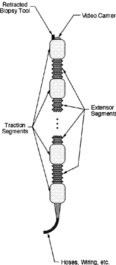
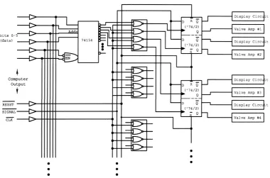
f
TUBING TO REGULATED HIGH PRESSURE SOURCE7
TUBLNG TO REGULATEDd
VACUUM SOURCEINTERFACE
COMPUTER CIRCUITRY
PROTOTYPE ROBOT
Figure 3.1: Schematic overview of a prototypical robotic endoscope system.
ations of the proof of concept prototypes is provided at the end of this chapter.
In these sections, the features and performance of each design will be provided.
3.1 System Overview
A schematic overview of the endoscopic robot system concept is shown in Figure 3.1; the reasoning behind this design will be provided in the following
sections. To investigate the various aspects of this technology, five distinct gen-
erations of proof of concept prototype robots were designed, built and tested.
Common to all of these prototypes is a locomotion system comprised of the
robotic mechanism with a trailing tether, an electronic control system, and
pneumatic sources and plumbing. Although the earliest robots relied upon
hard wired, digital, control electronics, later versions have been controlled by
serial signals from a laptop computer. In all these experimental prototype
lated compressed air and vacuum sources. Additionally, videocamera systems
for visualization within the lumen have been incorporated in the design of the
later versions.
This subsection will focus on the fundamental concepts that are common
to all five generations of experimental prototype robots.
Referring to Figures 3.2 and 3.3, these endoscopes can be considered elec-
tromechanical analogs of segmented worms, such as earthworms. These crea-
tures propel themselves by pushing against and stretching through their sur-
rounding environment in a coordinated manner. For this type of locomotion,
the robotic endoscope employs mechanisms along its length which can be de-
scribed as "grippers" and "extensors." The primary purpose of the grippers, or
traction devices, is to provide traction against the lumen wall by expanding ra-
dially outward. The extensors provide extensibility between the grippers, i.e.,
they cause the mechanism to locally stretch or shrink in length. Locomotion
is the process of generating net displacement of the robotic endoscope inside a
lumen by specific sequences of gripping and stretching actions. Such sequences
are commanded by an external computer, and thus changes in the selection
and control of mechanical movements can be easily accomplished in software.
Furthermore, these machines are not limited by their mechanical design to lo-
comote by a particular gripper and extensor sequence. This adaptability may
be required for robust locomotion through lumens which exhibit changing geo-
metric or material characteristics along their length e.g., intestinal curvature
or varying cross-sectional diameter
.
In addition, a large number of similar,or identical, mechanical elements can provide redundancy in the event of an
individual component failure; whenever possible, the robot should remain ca-
inoperative.
After much considerat ion of various actuation t ethnologies as well as the requirements of robotic endoscopy of the small intestine, fluid power was deter-
mined to be the most viable actuation technology. In contention were numer-
ous alternative approaches including electromagnetic actuation, shape memory
alloys, piezoelectric materials, and magnetostrictive materials. But fluid power
was chosen for the proof of concept prototypes and is a likely candidate for a
viable surgical instrument for the following reasons. Current endoscopic pro-
cedures often require carbon dioxide gas, saline solution, and partial vacuum
for insufflation (the medical term for inflation of body cavities), irrigation, and
suction of gastrointestinal lumens. Consequently, these features must be in-
corporated into the advanced, robotic endoscopes as well. Thus, these fluidic
power sources for mechanical actuation would also be available for the loco-
motion subsystem of the endoscope. And since large amounts of pneumatic
or hydraulic mechanical power can be controlled by small electric signals, this
approach could minimize the danger of electric shock to the patient. Hence,
Auid power would be a convenient and safe method for generation of substan-
tial actuation forces and displacements in these robotic devices. An additional
safety measure of these designs is that the working pressures of the Auid power
sources can be kept intentionally small thereby reducing the maximal forces
that the actuators can apply. In our prototypes, the high pressure source has
been typically maintained at or below 12 psig, while the low pressure has been
nominally - 14.2 psig (vacuum
In contrast, each of the competing technologies imposes unique and se- rious challenges to a robotic endoscope designer. Electromagnetic actuation
displacements when driven by relatively large electric currents; unfortunately.
such electric signals at work within the body can adversely impact patient
safety. Magnetostrictive and piezoelectric materials undergo minute deforma-
tions when subjected to large magnetic and electric fields: respectively; thus,
devices that utilize these materials must be designed to ('amplify" these small
mechanical effects. As with electromagnetic actuators, these devices are driven
by large electric signals; piezoelectric actuators typically require extremely
high driving voltages, and magnetostrictive actuators need large electric cur-
rents. Unfortunately, electrical currents as small as 5 milliamps through the
heart can cause death. And, finally, shape memory alloys produce mechanical
actions when heated, and resistive heating can cause them to rapidly change
shape. Unfortunately, rapid cooling of these materials can be very difficult (a
sophisticated cooling system may be required). Thus, in applications such as
robotic endoscopy, the time response of shape memory actuation may not be
sufficiently rapid.
For the aforementioned reasons, the decision to pursue a fluid power de-
sign is justified. But selection of pneumatics versus hydraulics remains an
unanswered question. The experimental, proof-of-concept prototypes utilize
pneumatics for a very practical reason. These machines have many potential
modes of failure, including leakage from hoses and actuators. Leakage of air,
especially after a catastrophic rupture of an actuator, does not require any
"clean up." In conversation, E. Zukoski at Caltech recommended use of the saline source (the surgical irrigation source for hydraulic actuation as it would
likely be a safer fluid power medium in the event of a mechanical rupture of
a robotic component. His contention is that the leakage of an incompressible
Unfortunately, if such a failure occurs, there is the possibility of a high velocity
saline jet causing laceration of the fragile intestinal membranes. The momen-
tum flux in a similar pneumatic jet would be considerably lower which could
reduce the deleterious cutting effect of a rupture. Clearly, both competing safety issues must be considered carefully before any such device is introduced
into a human being. And while the locomotion concepts espoused herein can
apply to the design of self-propelled endoscopes that crawl within any biolog-
ical lumen (such as blood vessels), the detailed design of these mechanisms
must reflect the specific needs of their respective applications. In this context,
the actuation technologies of the robotic gripper and extensor subcomponents
would be chosen for safe and dependable locomotion specifically with regard
to the relevant lumen and medical application.
The system described above must be packaged to function within the small
intestine. To characterize this environment, mat hematical descriptions of both
the geometric properties and elastic behavior of the intestine are required. As
one example, an estimate of the unstretched diameter of the small intestine is
an important parameter to specify the contracted diameter of the endoscopic
robot. Based on initial estimates, these robots should have a contracted di-
ameter of less than four-tenths of an inch, or ten millimeters, approximately.
To date, the thinnest robotic prototype that has been fabricated was approx-
imately seven-tenths of an inch (eighteen millimeters) in diameter. The cur-
vature of the small intestine imposes additional geometric constraints on the
design of these devices. The initial estimate for the minimum radius of cur-
minimum radius of curvature that the bendable segments of the robot must
achieve.
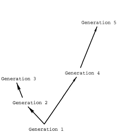
To date, the prototype design evolution has been dictated by a time con-
suming "build and test" method where engineering judgment has played a
large role. These mechanisms evolved over five generations. With each step of
this process, prototype components and systems were built to address specific
research issues. Such issues include, but are not limited to, fabrication tech-
nologies, locomot ion modalities, and system integration (mechanisms, elec-
tronics, and software
.
With each succeeding generation, the intended researchobjectives grew more ambitious, and the later versions manifested increased
sophistication in order to meet their design specifications. Building experi-
mental devices to "explore the design space" without a priori design analysis
can be an inefficient approach to developing a viable device. If one could ei-
ther analytically or numerically "test" each design before its fabrication, then
fewer developmental prototypes would likely be required before converging to
a viable final design. This motivated the investigation of the biomechanics
of the small intestine as reported in Chapter 4. This biomechanics analysis
and experiment at ion provided a foundation for a numerical simulation of the
interactions between the robot and the surrounding lumen (highlighted in Sec-
tion 4.6.3). It is expected that this modeling will be used in the design efforts
of future endoscopic robot components.
Lastly, all five generations of these proof of concept prototypes were de-
signed and fabricated solely with the available resources at Caltech. It is an-
t icipated t hat using common and affordable manufacturing t ethnologies, e.g .
,
injection molding, the necessary size and functionality goals can be met. Un-
as the production volume increases; in other words, they were prohibitively
expensive for these experiment a1 research activities.
3.2 Methods for Locomotion
A
gait is a distinct cycle of changes in the states of the component gripper andextensor segments that leads to a unit of displacement, which we term a strzde.
The displacement that results from one complete gaiting cycle is termed the
stride length. Repetition of a gait leads to net displacement, or locomotion.
If
the robot is comprised of more than two independently operated grippersegments connected by one extensor segment, it will be capable of locomotion
using more than one type of gait.
In Figures 3.4 through 3.8, several gaits are shown for endoscopes which are comprised of two, three and five gripper segments. One can think of
these figures as a vertical array of sequential snapshots of a robot as it moves
through a tube. For each element of these arrays, the phase, or state, of the machine is unique. And between the given phases, the conditions of expansion
of individual gripper and extensor segments change. Since all phases of these
locomotion gaits are aligned vertically in these figures, the stride length of
each gait shown can be deduced by comparing the location of the robot in
the first and last phases of the gait. While the lumen is represented as a
straight tube, the inch-worm type locomotion methods will work if the lumen is
curved and has reasonable variations in its cross-sectional shape and diameter.
This is possible because the robots are engineered to exhibit passive bending
compliance to lateral forces. Of course, active control of lateral bending of
the leading segments (although no existing prototype device has incorporated
active bending control).
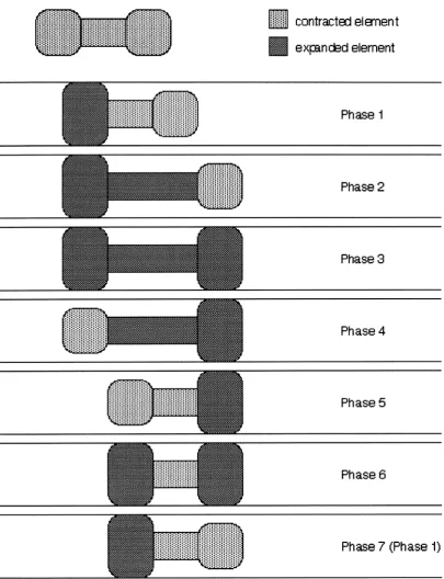
3.2.1
The Gait
of
a
2-Gripper/l-Extensor
Mechanism
For the purposes of illustration, let us first consider a locomotion method for a device consisting of two traction segments and one extensor segment, as
depicted in Figure 3.4. This is the simplest design that can generate endoscopic locomot ion.
A 2-gripperll-extensor mechanism can exhibit at most one type of inch-
worm gait. The sequencing of the gait for forward motion proceeds as follows
(in the diagram, forward motion means motion to the right). Let us assume
that the sequence begins with the aft traction device expanded to grip the
lumen wall (as indicated in the part of the diagram labeled "phase 1"). Mean-
while, the forward gripper and the extensor are in their retracted states. The
extensor device is then lengthened (phase 2). While the extensor will typically
be expanded to its full length, partial extension is also possible. If the lumen is
curved and sufficiently rigid, the lateral compliance of the extensor will cause
the expanding extensor to move in the principle direction of the lumen. After
the extension is complete, the forward traction device is expanded to grip the
lumen wall (phase 3). Once the forward gripper has grown, the rear gripper
is retracted (phase 4). The extensor is then retracted (phase 5 ; typically, the
extensor will be retracted to its shortest length, although partial retraction is
possible. Subsequently, the rearward gripper is expanded to grip the lumen
.
And finally, the forward gripper is retracted. At this point,;i;i;iii contracted el emen t
expnckd element
Phase 1
Phase 2
Phase 3
Phase 4
Phase 5
Phase 6
[image:42.616.117.523.109.638.2]Phase 7 (Phase 1)
Figure 3.4: Schematic diagram of locomotion for a 2-Gripper/ 1-Extensor
the robot has moved forward by a one stride length. Assuming no slip, the
stride length is the difference between the extended extensor length of phase
2, and the retracted extensor length of phase 5 .
These steps comprise a single gait cycle. This cycle can be repeated to
provide continual motion. It can also be reversed to implement motion in the
opposite) direction. Loosely speaking, this gait may be termed a "standing wave" gait (using the terminology of Chirikjian and Burdick
[
since the movement of the extensor can be thought of as a body fixed oscilla-
tion.
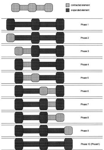
3.2.2 Some Gaits for a 3-Gripper/2-Extensor Mecha-
nism
Let us now consider means by which a device consisting of 3 grippers and 2
extensors can crawl (e.g., the robot shown in Figure 3 . 2 ) . This version can
manifest locomotion using at least ten distinct gaits. Detailed descriptions of
two of these gaits will highlight important characteristics of the device. Also,
Figure 3.7 provides self-explanatory schematics of additional gaits.
The first gait which we will characterize is elucidated in Figure 3.5. In
phase 1 , all of the grippers and extensors are in their expanded states. The
rear gripper is retracted in phase 2. Next, the rear extensor is retracted (either
partially, or fully) in phase 3. Subsequently, the rear gripper is expanded to
make contact with the lumen (phase 4
.
In
phase 5 , the middle gripper isretracted. Then, in phase 6, the rear extensor is extended while forward extensor is retracted.
In
phase 7, the middle gripper is expanded to makePhase 1
Phase 2
Phase 3
Phase 4
Phase 5
Phase 6
Phase 7
Phase 8
[image:44.616.144.493.121.622.2]Phase 10 (Phasel)
followed by an extension of the forward extensor. Finally, in phase 10, the
forward gripper is again expanded. At this point the mechanism has returned
to its original state and has advanced by one stride length. As before, this cycle
is repeated for continual forward movement and can be reversed for rearward
motion.
From the explanation of this gait sequence, it can be seen that the robot's
contact with the lumen wall occurs in a "wave-like" manner. Hence, we can
describe this motion sequence as a "traveling wave gait" in much the same
manner as those described by Chirikjian and Burdick for hyper-redundant
robots [7]. The robot's configuration changes as a body fixed traveling wave of
compression; similarly, a traveling expansion wave gait also exists. It should be
recounted that lateral compliance of the extensors will enable the mechanism
to move in sufficiently rigid, curved lumens as well. Furthermore, it is clear
that at any instant, only relatively short segments of the device are being
pushed forward through the lumen. This should abate the buckling problems
inherent in conventional endoscope designs.
Also noteworthy is that, in this gait, at least two gripping devices make
contact with the lumen at all times. Consequently, a three gripper robot
employing this gait would be able to more robustly grasp the lumen than
it would using any gait that provides traction from only one gripper during
certain phases of the gait.
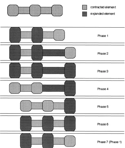
Figure 3.6 shows a second example gait for a 3-gripper/ 2-extensor device.
It should be noted that in all phases of this gait, the rear extensor is retracted;
this gait functions without operation of the rear extensor. And the same se-
quence of maneuvers could also be used if the rear extensor were extended.
:::::::
.... ... contrwtcxl el men t expm&d element
Phase 1
Phase 2
Phase 3
Phase 4
Phase 5
Phase 6
[image:46.622.107.533.118.622.2]Phase 7 (Phase 1)
Figure 3.7: Schematic diagrams of additional locomotion gaits for a 3- gripper 12-ext ensor mechanism.
event of a rear extensor segment failure. Similarly, gaits exist that provide
locomotion after any single actuator failure (provided that a failed gripper re-
mains in its retracted state). Reiterating, the 3-gripperl2-extensor device can
exhibit ten subst antially different gaits. Such redundancy could be expected
to contribute to increased safety of the overall system.
3.2.3
Gaits for Designs with Numerous Grippers and
Extensors
As the number of grippers and extensors in the robotic endoscope design
increases, so does the number of possible gaits. For example, Figure 3.8 shows
could systematically develop the sequences for all possible gaits for any such
robot using the ideas outlined in the previous subsections.
In general, it is advantageous for an endoscopic robot to be capable of a
large number of gaits. Such endoscopes must have many gripper and exten-
sor segments. As shown above, some gaits typically have more grippers in
simultaneous contact with the lumen, e.g., traveling wave gaits. These gaits
tend to be more stable, though the progress of the device through the lumen
will be slower (as measured by the number of required phase changes and the attendant stride lengths). A slower but more robust gait would be useful when the robot moves into region of the lumen where traction is minimal. Further-
more, gaits with more grippers in contact can generate greater traction forces
without excessive normal contact loadings; this might be useful for unblock-
ing intestinal blockages/narrowing. Conversely, it may be desirable to select
a faster gait when the robot moves into a region of strong traction and vital,
healthy tissue. In addition, there exist gaits which are robust to the failure
of particular components, as illustrated in Figure 3.6. The ability to switch between gaits as the situation dictates is a key feature of this device.
3.3
Prototype Component Designs
This section conceptually describes mechanisms which can implement the me-
chanical actiom outlined above. As noted in 3.1, these machilies consist af a serial chain of grippers and extensors. And the qualitative, experimental
results discussed in Section 3.5 suggest that more than two gripper segments connected by one extensor segment will be necessary to provide dependable