International Conference on Mechanical Engineering Research (ICMER2013), 1-3 July 2013 Bukit Gambang Resort City, Kuantan, Pahang, Malaysia Organized by Faculty of Mechanical Engineering, Universiti Malaysia Pahang Paper ID: Keynote_Speaker03
1
MILD COMBUSTION: THE FUTURE FOR LEAN AND CLEAN COMBUSTION
Talal Yusaf1,2, M.M.Noor2,3and Andrew P.Wandel3
1
National Centre for Engineering in Agriculture, USQ, Australia 2
Faculty of Mechanical Engineering, Universiti Malaysia Pahang (UMP), Malaysia 3
Computational Engineering and Science Research Centre, Department of Mechanical and Mechatronic Engineering, University of Southern Queensland (USQ), Australia
Email: [email protected], [email protected], Phone: +607-46311783
ABSTRACT
Energy security is becoming an important and intergovernmental issue due to the depletion of fossil fuel. This paper discusses the energy needs and the new combustion technology that will aid in achieving lean and clean combustion.In 2001, British Petroleum estimated the total natural gas reserves to be 187.5 trillion cubic meters, which can supply up to 7x10¹⁵ MJ of energy. The total petroleum reserves can supply up to 1,383 billion barrels which amounts to 8.4x10¹⁵ MJ of energy. Due to the increasing population and economic development, these fuel reserves will not last long. Energy efficiency and greenhouse gas emissions are two important and critical issues. The new combustion technology, moderate and intense low oxygen dilution (MILD) combustionprovides a feasible solution. MILD, also known as flameless oxidation (FLOX) and high temperature air combustion (HiTAC) was discovered by Wünning in 1989. The thermal efficiency of combustion can be increasedby about 30% and NOx emission reduced by 50%. MILD also can be achieved using different types of fuel such as gas fuel, liquid fuel and industrial waste fuel (saw dust).MILD combustion will be an important futurecombustion technology due to it producing higher efficiency and very low emissions.
Keywords: energy security; MILD combustion; biogas; world energy policy
INTRODUCTION
2
[image:2.595.184.417.132.328.2]2005). IEA/OECD (2002) and Jonathan (2006) reported that CO2 contributed 77% of the greenhouse gas emissions with combustion accounting for 27%, making it a major contributor to global climate change.
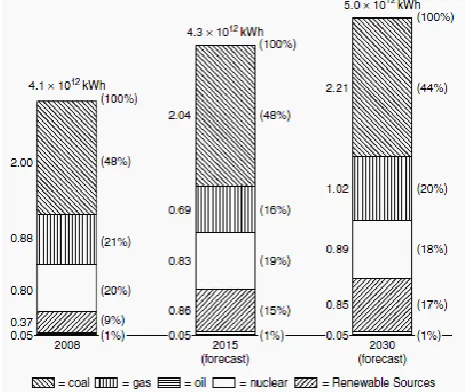
Figure 1. US electrical energy generation (US EIA, 2010).
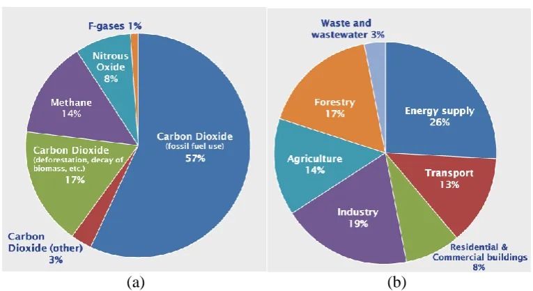
[image:2.595.122.477.540.671.2]Table 1 compares the pollutants from natural gas, oil and coal. The use of natural gas will reduce the impact of fossil fuel combustion on climate change. In order to further reduce NOx and other harmful pollutants, lean mixtures will reduce the combustion temperature and decrease the formation of NOx. Pollutant emissions are reduced because flame temperatures are typically low, reducing thermal NOx formation.Beside fuel NOx and prompt NOx,thermal NOx is the key NOx formation that will increase rapidly after the combustion temperature reaches 1573 K (EPA, 1999) and 1810 K (AET, 2012). Figure 2 illustrates the GHG emissions by type of gas and source. Figure 2(a) clearly indicates that carbon dioxide from fossil fuel combustion accounts for 57%, the majority of the GHG emissions. Figure 2(b) shows that 26% of GHG emissions originated from energy production.
Table 1. Pollutants from fossil fuel (US EIA, 1999).
No. Pollutant Gas Oil Coal
(kg of pollutant per 109 kJ of energy input)
1. Carbon dioxide 273,780 383,760 486,720
2. Carbon monoxide 94 77 487
3. Nitrogen oxide 215 1,048 1,069
4. Sulphur dioxide 2.34 2,625 6,063
5. Particulate 16.4 197 6,420
3
[image:3.595.106.489.80.289.2](a) (b)
[image:3.595.163.436.381.597.2]Figure 2. Global greenhouse gas emissions a) by type of gases, b) by type of sources (IPCC, 2007).
Figure 3 plots the formation of NOx. In order to achieve low NOx emissions, the flame temperature of the combustion must be below 1425oC (1698 K). Above that temperature, the NOx formation will be very high.
Figure 3. The rate of NOx formation forflame temperature (AET, 2012).
4
This paper willdiscuss the future of MILD combustion and its ability toprovide lean and clean combustion.The continualsignificant demand for cheap and clean energy coupled with the unclear fossil fuel reserves and limitations on other source of energy provides increasing pressure for the combustion community to improve the overall combustion efficiency with minimum pollution emission.
LEAN COMBUSTION AND CLEAN COMBUSTION
Lean combustion is defined as achieving the combustion stability process with a minimum amount of fuel. Whereas clean combustion is to achieve the lean combustion process with zero or minimum unwanted pollutants. Lean combustion is applicable and used in all combustion equipment at both laboratory and industrial scale including internal combustion engines, burners, gas turbines, furnaces, boilers and kiln. This is to take advantage of the combustion processes that operates with minimum or lean conditions with very low pollutant emissions and very high efficiency.
In the hazard of combustion study, like explosive, hazard and flammability limit, lean combustion are very important for the setting of any fuel’s limit of inflammability.Davy (1816) studied lean combustion to prevent explosions of methane gas in coal mines. Davy reported that the limits of inflammability were between 6.2 and 6.7%, which is same as an equivalence ratio range for methane between 0.68 and 0.74. The challenging behaviours of lean flames include sensitivity to fuel composition and relatively weak reaction fronts in highly dynamic fluid flows (Rankin, 2008). Lately beside the combustion process, fuel studies also get attention for lean and clean research. A Maryland-based independent power provider (IPP) combustion company has developed an innovative patented technology for Lean, Premixed, Prevaporised (LPP) combustion of fuels, hence, these fuels burn cleanly in gas-fired power turbines and other combustion devices (IFP, 2010). Biofuel is also part of the fuel study for better performance with lower exhaust emission (Ghobadian et al., 2009; Yusaf et al., 2011; Najafi et al., 2011; Noor et al., 2012a).
MILD COMBUSTION REGIME
MILD combustion is a revolutionary mode of burning that dramatically improves the efficiency of a furnace while substantially reducing the pollutants that are produced (Tsuji et al., 2003; Choi and Katsuki, 2001; Dally et al., 2004; Medwell et al., 2007; Noor et al., 2012c; Abtahizadeh et al., 2012). While most research has focussed on “closed furnaces”, which have a simpler configuration at a substantially increased cost of construction, USQ is developing an “open furnace” system, which is similar to many furnaces currently in use (Noor et al., 2012c). Retrofitting an open furnace system to operate under MILD conditions is relatively straightforward: it merely requires the addition of recirculation pipes (Exhaust Gas Recirculation, EGR) (Noor et al., 2012c) making this an appealing option.
5
[image:5.595.118.474.211.490.2]The oxygen dilution plays the most important rolein achieving MILD combustion as shown in a step by step illustration of oxygen dilution in Figure 5. Recent applications of MILD combustion have been in research and development of gas turbines (Duwig et al., 2008; Arghode and Gupta, 2010, 2011) and gasification systems (Tang et al., 2010, 2011). This combustion mode can be very interesting in gas turbine applications due to low maximum temperatures (very close to the ones at the inlet of a gas turbine), noiseless characteristics, good flame stability and effectiveness in reducing pollution emissions.
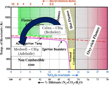
Figure 4. Schematic regime diagram for methane-air JHC flames (Rao, 2010 and Chen at al., 2012).
6
Figure 5. Step by step of MILD combustion a) combustion started, b) to d) progressively more dilute oxygen e) fully MILD combustion (Dally et al., 2012)
BIOGAS AND ENERGY BALANCE
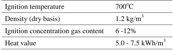
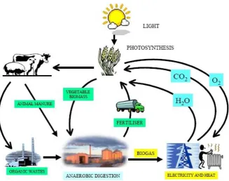
Biogas is a clean and renewable energy whichisalow heating value gas,also known as low calorific value (LCV) gas. Biogas consists of a mixture of 55 to 65% of methane, 35 to 45% of carbon dioxide and 1-3% of hydrogen sulphide, nitrogen, hydrogen, oxygen and ammonia (Balat and Balat, 2009). Biogases are commonly produced from waste treatment, mainly agricultural waste (manure), industrial organic waste streams and sewage sludge (Hartmann and Ahring, 2005). Figure 6 shows the CO2 cycle for biogas. Carbon dioxide produced from combustion will be used back by the crops and some of these crops are fed to animals. These crops and animal manure will be used to produce biogas. Table 2 shows the typical combustion properties of biogas. The average biogas ignition point is 700oC but this depends on the percentage of methane. The higher the methane the lower will be the ignition temperature.
Table 2. Combustion properties of biogas (Balat and Balat, 2009).
Ignition temperature 700oC
Density (dry basis) 1.2 kg/m3
Ignition concentration gas content 6 -12%
[image:6.595.154.440.438.523.2]7
Figure 6. Carbon dioxide closed cycle for biogas (The Sietch, 2013).
[image:7.595.93.501.474.679.2]Table 3 show a comparison of energy balance for natural gas with 97% methane. The summary was made for the furnace whichoperates in the flameless mode and conventional mode with natural gas. The supply of thermal energy was constant at about 21 kW for both conditions.
Table 3. Natural gas energy balance (Colorado et. al, 2010).
Combustion mode Flameless mode Conventional mode Energy input (includingfuel +
combustionair + cooling air) (kW)
21.31 21.02
Energy losses through the wall
(kW) 3.07 3.20
Energy removed by thecooling
tubes (kW) 14.99 8.71
Energy output throughthe
chimney (kW) 1.39 8.25
Energy of the
combustionproducts after theregenerative system (kW)
1.36 0
Efficiency (%) 70.0 41.4
8
EXHAUST GAS RECIRCULATION
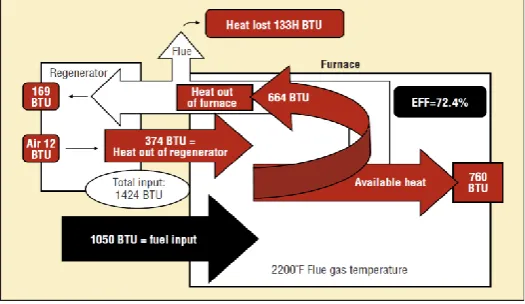
In conventional combustion, about 62% of the energy input to the combustion process will be lost through exhaust gas(figure 7).Part of these heat losses can be recovered by the concept of Exhaust Gas Recirculation (EGR).EGR works by recirculating a portion of the flue gas back to the combustion chamber through EGR pipe. Weinberg (1996) demonstrates this in his famous Swiss-roll burner by transferring the heat from burned products to the unburned fresh mixture.
[image:8.595.166.432.301.456.2]The comparison of combustion with and without EGR can be seen in Figure 7 and 8. The furnace in Figure 7 is running without a regenerator (EGR) and 654 BTU of heat is lost through flue gas. The difference for Figure 8 is the furnace running with the regenerator (EGR) and from 654 BTU of heat in the flue gas; only 133 BTU is lost through flue gas to the atmosphere. Some of the 521 BTU of heat is returned back to the system via the regenerator. The efficiency is 37.4% for the system without EGR and 72.4% for the system with EGR and the system with EGR is 35% higher.
Figure 7. Efficiency of the heating system without EGR (Kraus and Barraclough, 2012).
Figure 8. Efficiency of the heating system with EGR (Kraus and Barraclough, 2012).
[image:8.595.166.429.496.648.2]9
[image:9.595.236.364.502.722.2]Figures 9 and 10 show the industrial furnace with the heat exchanger system and internal gas recirculation to utilize the flue gas.
Figure 9. Industrial furnaces with heat exchanger system (Mulliger and Jenkin, 2008).
10
MILD COMBUSTION FURNACE
MILD combustion technology is new to the furnace industry and it is not fully commercialized and well adopted in furnace industry.In the Jan 2012 edition of Industrial heating magazine, it is written that new configurations (utilisation of EGR) may make it harder to say no to thermal regeneration (Kraus and Barraclough, 2012). To further improve the combustion process, it is very important to conduct substantial fundamental and applied research (Cavaliere et al., 2008, Yusaf et al., 2010, Li et al., 2011, Parente et al., 2011,Danon, 2011, Rahman et al., 2011,Kamil et al., 2011, 2012,Noor et al., 2012a; Hamada et al., 2013).To achieve MILD combustion, the fuel and oxidant mixing is very important. The mixing process is coupled between turbulence and chemistry (Parente et al., 2008) occurring at similar timescales (Plessing et al., 1998; Galletti et al., 2007), thus, the turbulence-chemistry interactions should be treated with finite-rate approaches. The level of homogeneity of the mixing field (Joannon et al., 2010) and slower reaction rates make the accurate modelling of this combustion regime challenging (Aminian et al., 2011). This is especially the case for the heat release rate, NOx and soot formation, thus, a fundamental study on the mixing quality is required.
The furnaces for MILD combustion are greatly invested at a laboratory scale and at industrial scale;gradual adaptations are taking place for this new technology. Worldwide there are many research labs and universities are conducting further research, an example of this is shown below in Figure 11. Figure 11(a) is MILD combustion in an open furnace at University of Southern Queensland (USQ), Australia (Noor et al. 2012c). This is the first to be declared as a MILD combustion open furnace since the opening at the top allows substantial exhaust gas to flow out. Figure 11(b) is the closed furnace of MILD combustion at University of Adelaide, Australia. The furnace is also successful in using saw dust as a fuel as an alternative to normal gaseous fuels (Dally et al. 2010). Figure 11(c) is the MILD setup at Politecnico di Milano, Italy (Derudi and Rota, 2011). This MILD burner is using a double nozzle for jet fuel.
[image:10.595.95.505.502.687.2]a) b) c)
Figure 11.MILD combustion furnace, a)University of Southern Queensland, Australia (Noor et al., 2012a), b) University of Adelaide, Australia (Szego et al., 2008; Dally et
11
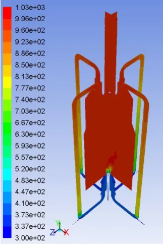
[image:11.595.216.378.132.374.2]The results for the Computational Fluid Dynamics (CFD) on open furnace are as Figure 12. The temperature distribution in the combustion chamber is homogeneous.
Figure 12. MILD combustion achieved (Noor et al., 2012a).
For theUSQ combustion group, the experimental setup is not only for MILD combustion but can be used for a wide range of combustion and ignition studies in the future: testing the characteristics of alternative fuels under combustion, including natural gas, biogas and coal seam gas. Biogas and LCV fuels are difficult to burn in a conventional combustor, but are readily burned in MILD mode (Colorado et al., 2010, Dally et al., 2010), so the potential exists to lead the world in both open furnace MILD systems and the usage of alternative fuels (Noor et al., 2012a, 2012b, 2012c). This also has great potential for consulting work with local industries to improve their green characteristics, and therefore, could lead to substantial future research and development opportunities.
CONCLUSION
Lean and clean combustion is a must in today’s energyproduction in order to cater the critical energy supply. The other critical issue is the demand for agreener world leads to the reduction of greenhouse gases and more environmental friendly energy production. MILD combustion technology and its characteristicsare very impressive and ithas the potential to be the real future of combustion for lean and clean energy. MILD combustion produced a 30 to 35% improvement in thermal efficiency through the re-use of heat from exhaust gas. At the same time, MILD combustion also reduced the NOx emissions by 50%. USQ combustion group is the first to research the MILD combustion in an open furnace.
12
combustion techniquescoupledwith the use of biogas as a fuel proves to be the perfect match for the future of lean and clean combustion technology.
ACKNOWLEDGMENTS
The authors would like to thank University of Southern Queensland (USQ) and Universiti Malaysia Pahang (UMP) for providing financial support and laboratory facilities.
REFERENCES
Abtahizadeh, E., Oijen, J.V. and Goey, P.D. 2012. Numerical study of mild combustion with entrainment of burned gas into oxidizer and/or fuel streams, Combustion & Flame 1596:2155-2165.
AET. 2012. The formation of NOx, Allied Environmental Technologies, Inc,
http://www.alentecinc.com/papers, accessed on 14 Jun 2012.
Aminian, J., Galletti, C., Shahhosseini, S. and Tognotti, L. 2011. Key modeling issues in prediction of minor species in diluted-preheated combustion conditions, Applied Thermal Engineering, 31, pp. 3287-3300
Arghode, V.K. and Gupta, A.K. 2010.Effect of flow field for colorless distributed combustion (CDC) for gas turbine combustion.Applied Energy, 87(5):1631-1640. Arghode, V.K. and Gupta, A.K. 2011.Development of high intensity CDC combustor
for gas turbine engine.Applied Energy, 88:963-973.
Balat, M. and Balat, H. 2009. Biogas as a renewable energy source a review, Energy Sources, Part A: Recovery, Utilization, and Environmental Effects, 41(14), 1280-1293.
BP. 2011. Statistical review of world energy, BP PLC, Cedigaz, Paris, France
Cavaliere, A. and de Joannon, M. 2004. MILD combustion. Progress in Energy and Combustion Science, 30:329-366.
Cavaliere, A., de Joannon, M. and Ragucci, R. 2008.Highly preheated lean combustion. In: Dunn-Derek, D. (ed.) Lean combustion: technology and control. Oxford, UK, Elsevier, 55-94.
Chen, J., Kolla, H., Grout, R., Gruber, A., Yoo, C., Knudsen, E. and Pitsch, H, 2012. Modelling of lifted flames in vitiated coflow: insight and challenges from DNS, TNF 11 Workshop, 26-28 July 2012,Darmstadt, Germany.
Choi, G.M. and Katsuki, M. 2001. Advanced low NOx combustion using highly preheated air, Energy Conversion and Management, 425:639-652.
Colorado, A.F., Herrera, B.A. and Amell, A.A. 2010. Performance of a flameless combustion furnace using biogas and natural gas, Bioresource Technology, 101(7):2443-2449.
Dally, B.B, Li, P and Mi, J. 2012, MILD oxy-combustion of gaseous fuels, TNF 11 Workshop, 26-28 July 2012,Darmstadt, Germany.
Dally, B.B, Riesmeier, E. and Peters, N. 2004. Effect of fuel mixture on moderate and intense low oxygen dilution combustion, Combustion & Flame 137(4): 418-431. Dally, B.B., Karpetis, A.N. and Barlow, R.S. 2002. Structure of turbulent non-premixed
jet flames in a diluted hot co-flow, Proceedings of the Combustion Institute, 29(1): 1147-1154.
13
Danon, B. 2011.Furnaces with multiple flameless combustion burners, PhD Thesis, TechnischeUniversiteit Delft, Germany.
Davy, H. 1816. On the fire-damp of coal mines, and on methods of lighting the mines so as to prevent its explosion, Philosophical Transactions of the Royal Society, London. 106, 1-22.
Derudi, M. and Rota, R. 2011. Experimental study of the MILD combustion of liquid hydrocarbons, Proceedings of the Combustion Institute 33:3325-3332.
Duwig C., Stankovic D., Fuchs L., Li G. and Gutmark E. 2008. Experimental and numerical study of flameless combustion in a model gas turbine combustor, Combust Science and Technology, 180(2), pp. 279–295
Galletti, C., Parente, A. and Tognotti, L. 2007. Numerical and experimental investigation of a MILD combustion burner, Combustion and Flame, 151(4), 649– 664
Ghobadian, B., Rahimi, H., Nikbakht, A.M., Najafi, G. and Yusaf, T.F. 2009. Diesel engine performance and exhaust emission analysis using waste cooking biodiesel fuel with an artificial neural network, Renewable Energy, 34(4), 976-982
Hamada, K.I., Rahman, M.M., Abdullah, M.A., Bakar, R.A. and Aziz, A.R.A. 2013.Effect of mixture strength and injection timing on combustion characteristics of a direct injection hydrogen-fueled engine. International Journal of Hydrogen Energy, 38: 3793-3801.
Hartmann, H. and Ahring, B.K. 2005.The future of biogas production, Riso International Energy Conference on Technologies for Sustainable Energy Development, in the Long Term. Riso-R-1517(EN), Roskilde, Denmark, May 2325, pp. 163172.
IEA, 2006. World Energy Outlook (WEO), International Energy Agency, IEA, Paris IEA. 2009. World Energy Outlook. Paris,International Energy Agency.
IEA/OECD, 2002. CO2 Emissions from Fuel Combustion: 1971–2000, Organisation for Economic Cooperation and Development and Int. Energy Agency, Paris
IFP, 2010. Lean and clean combustion fuel, Industrial Fuel and Power, Brazil.
IPCC. 2007. Contribution of Working groups I, II and III to the fourth assessment report of the intergovernmental panel on climate change, IPCC.
Joannon, M. D., Sabia, P. and Cavaliere, A. 2010. MILD combustion, in handbook of combustion, Vol. 5, edited by Lackner M, Winter F and Agarwal AK, Wiley-Vch, Weinheim.
Jonathan, P. 2006 Responses to questions on the design elements of a mandatory market-based greenhouse gas regulatory system, World Resources Institute, Washington.
Kamil, M., Rahman, M.M. andBakar, R.A. 2011. Performance evaluation of external mixture formulation strategy in hydrogen fuelled engine. Journal of Mechanical Engineering and Sciences, 1: 87–98.
Kamil, M., Rahman, M.M. andBakar, R.A. 2012.Modeling of SI engine for duel fuels of hydrogen, gasoline and methane with port injection feeding system, Energy Education, Science and Technology, 29(2): 1399–1416.
Katsuki, M. and Hasegawa, T. 1998. The science and technology of combustion in highly preheated air. Proceedings of the Combustion Institute, 27 (2):3135-3146. Kraus B.J. and Barraclough S. 2012. New configuration may make it harder to say no to
14
Li P.F., Mi J.C., Dally B.B., Wang, F.F., Wang, L., Liu, Z.H., Chen, S. and Zheng C.G. 2011. Progress and recent trend in MILD combustion, Science China Technology Science, 54, pp. 255-269
Maczulak, A. 2010.Renewable energy, sources and methods.New York, USA, Facts on File Inc.
Medwell P.R., Kalt P.A.M. and Dally B.B. 2007. Simultaneous imaging of OH, formaldehyde, and temperature of turbulent nonpremixed jet flames in a heated and diluted coflow, Combustion and Flame, 148(1-2), pp. 48–61
Metal Finishing, 2013 http://www.metalfinishing.com, accessed on 01 March 2013 Mullinger, P and Jenkins, B 2008 Industrial and Process Furnaces: Principles, Design
and Operation, Elsevier, Oxford, UK.
Najafi, G., Ghobadian, B. and Yusaf, T.F. 2011. Algae as a sustainable energy source for biofuel production in Iran: a case study, Renewable and Sustainable Energy Reviews, 15(8), 3870-3876.
Noor M.M., Wandel, A.P. and Yusaf, T. 2012a.A review of MILD combustion and open furnace design consideration, International Journal of Automotive and Mechanical Engineering, 6, 730-754.
Noor M.M., Wandel, A.P. and Yusaf, T. 2012b. The modelling of the effect of air fuel ratio on unburned hydrocarbons for MILD combustion, 2nd Malaysian Postgraduate Conference, 7-9 Jul, Bond University, Gold Coast, Australia, Paper No. MPC2012-27: 159-163.
Noor M.M., Wandel, A.P. and Yusaf, T. 2012c.Numerical investigation of influence of air and fuel dilution for open furnace mild combustion burner, Southern Regional Engineering Conference, Engineers Australia, 1-2 Sept, USQ, Paper No.SREC2012-002.
Orr, F. 2005. Energy and climate: challenges and solutions. GCEP, Stanford University Parente, A., Galletti, C. and Tognotti, L. 2008. Effect of the combustion model and
kinetic mechanism on the MILD combustion in an industrial burner fed with hydrogen enriched fuels, International Journal of Hydrogen Energy, 33, 7553-7564.
Parente, A., Sutherland, J.C., Dally, B.B., Tognotti, L. and Smith, P.J. 2011. investigation of the mild combustion regime via principal component analysis, Proceedings of the Combustion Institute, 33, 3333-3341
Plessing, T., Peters, N. and Wünning, J.G. 1998. Laser optical investigation of highly preheated combustion with strong exhaust gas recirculation, Proceedings of the Combustion Institute, 27(2), 3197-3204
Rahman, M.M., Kamil, M. andBakar, R.A. 2011.Engine performance and optimum injection timing for 4-cylinder direct injection hydrogen fuelled engine. SimulationModeling Practice Theory, 19(2): 734–751.
Raj, C. and Sendilvelan, S. 2010. Effect of oxygenated hydrocarbon additives on exhaust emission of a diesel engine, International Journal of Automotive and Mechanical Engineering, 2:144-156
Rankin, D.D. 2008. Lean combustion: technology and control, Academic Press, Amsterdam
Rao, 2010, in session on lifted flames in hot co-flow Coordinator: Gordon R and Roekaerts D, TNF 10 Workshop, 29-31 July 2010, Tsinghua University Beijing. Shafiee S. and Topal E. 2009. When will fossil fuel reserves be diminished, Energy
15
Szegö, G.G., Dally, B.B. and Nathan, G J. 2008. Scaling of NOx emissions from a laboratory-scale MILD combustion furnace, Combustion Flame, 154: 281-295. Tang Y., Wu J., Ma A., Gou X., Liu L. and Wang E. 2011. Effect of recirculated flue
gas position on combustion and NOx emission for high temperature air combustion, International Conference on Computer Distributed Control and Intelligent Environmental Monitoring, IEEE, pp. 1177-1180
Tang Z.G., Ma P.Y., Li Y.L., Tang C.J., Xing X.J. and Lin Q.Z. 2010. Design and experiment research of a novel pulverized coal gasifier based on flameless oxidation technology, Proc CSEE, 30(8), pp. 50–55
The Sietch, 2013 http://www.blog.thesietch.org, accessed on 01 March 2013
Tsuji H., Gupta A., Hasegawa T., Katsuki M., Kishimoto K. and Morita M. 2003.High temperature air combustion, from energy conservation to pollution reduction, CRC Press, Boca Raton, Florida.
US EIA. 1999. Natural Gas Issues and Trends, Technical Report DOE/EIA-0560(1999), Energy Information Administration, US Department of Energy, Washington DC. US EIA. 2010., Annual Energy Outlook 2010 Early Release, Technical report, US
Energy Information Administration.
US EPA. 1999. Nitrogen Oxides (NOx), why and how they are controlled, Technical Report EPA-456/F-99-006R, Clean Air Technology Center, US Environmental Protection Agency, North Carolina, US
Weinberg F.J. 1996. Heat-recirculating burners: principles and some recent developments, Combustion Science and Technology, 121:3-22.
Wünning, J. 1991. Flammenlose oxidation von
BrennstoffmithochvorgewärmterLuft.ChemieIngenieurTechnik, 63(12): 1243-1245.
Wünning, J.A. and Wünning, J.G. 1997. Flameless oxidation to reduce thermal no-formation. Progress in Energy and Combustion Science, 23 (1):81-94.
Wünning, J.G. 1996. Flammlose oxidation von Brennstoff.PhD Thesis, University of Technology, Aachen.
Yusaf, T.F., Buttsworth, D.R., Saleh, K.H. and Yousif, B.F. 2010. CNG-diesel engine performance and exhaust emission analysis with the aid of artificial neural network, Applied Energy, 87(5), 1661-1669