LECTURER ROOM DIRECTOR/MESSAGE BOARD
MOHDSHAMSULANUARBMOHDSABru
This Report Is Submitted Ln Partial Fulfillment of Requirements for the Bachelor /
Degree of Electronic Engineering (Industrial Electronic)
Tajuk Projek
Sesi Pengajian
Saya
UNIVERSTI TEKNIKAL MALAYSIA MELAKA
FAKUL Tl K.EJURUTERAA ELEKTRONlK DAN K.EJURUTERAAN KOMP fER
BOR>\."G PE~Gt:SAEIAN STATU LAPOR-'\N PROJEK SARJANA MUDA II
LECTURER ROOM DLRECTOR I MESSAGE BOARD
2006/2007
MOHO SI-IAMSUL ANUAR B MOHO SABRI
mengaku membenarkan Laporan Projek Sarjana Muda ini disimpan di Perpustakaan dengan sy arat-syarat kegunaan seperti berikut:
I. Laporan adalah hakmilik Universiti Teknikal Malaysia Melaka.
2. Perpustakaan dibenarkan mcmbuat salinan unluk tujuan pengajian sahaja.
3. Perpustakaan dibenarkan membuat salinan laporan ini sebagai bahan pertukaran antara institusi pengajian tinggi.
4. ila tandakan ( .J ) :
D
SllLIT*D
TERHAD•[2J
Tll)AK TIRHAOAlamat Tetap· Jalan Tok Hussein.
(Mengandungi maklumat yang berdarjah kcselamatan atau kepenlingan Malaysia scperti yang lermaktub di dalam A KT A RAH lA RASMI 1972)
(Mengandungi maklumatterbad yang Lelah ditentukan oleh organisasilbadan di mana pcnyelidikan dijalankan)
Disahkan oleh:
(COP
Kg Temelong,.33~00 Lenggong.. Pera~ Darul Ru:lman
MAJSARAH BT ABU Kerua JIJO«ilf! (Ke1 reletomvnikBSi]
Fai~ ~ E~il Oan ~e, I(O<Tlpllter (FKEKK).
Tarikh 7 May 2007
Ulli~l"lll Te,Mal lo4alaySICI Mataka (UTeM).
1(.)1'\lt~g Benl.unci 1 }()(), A,e~ Kiron. 7S450 ~a
DECLARATION
"I hereby declare that this thesis is the result of my own effort except as clearly
stated its references"
Signature
Author
Date
I dedicate to my father and my mother, family members
and last but not least, to all my lecturers and friends
ACKNOWLEDGEMENT
First of all, praise to the Eternal One, Allah S.W.T. for blessing and guiding
me through this entire project and gave me physical and mental strength so that I can
complete this project.
Special thanks to Mrs. Maisarah bt Abu, who always provide important
information and valuable suggestion for this project. Without her encouragement and
guidance, this thesis would never materialize. I appreciate for everything that she has
done to make this project a success. May Allah bless her life and family forever.
I also want to express my heartfelt gratitude and thanks to my beloved parents
who are right now in Uzbekistan. They always give me support and motivation to
finish this project.
Not to forget. to all my friends for always being there whenever
r
am in trouble and help me in through the darkest day. ln particular to all my housemate.Last but not least, to anyone who contributed their help and time who has directly or
VI
ABSTRACT
The aim for this project is to build a message board using dot matrix display.
The message board consists of four major subsections. These sections include a
computer program, a communications system, a microcontroller, and the LED
display. The computer program takes text entered by the user, converts the text to the proper data format, and loads the message onto the board.
The communications system handles data flowing from the computer to the
message board. The message board is connected to the computer using RS232 cable.
Data coming in from the computer is handled by the microcontroller, which stored
the data in memory. The microcontroller is also responsible for reading instructions
and messages from memory then displaying the messages according to the
instructions. The LED display is operated by a set of constant current display
drivers. These display drivers light the LED's based on data received from the
II
ABSTRAK
Tujuan penghasilan projek ini adalah untuk membina paparan mesej dengan
menggunakan paparan dot matrix.Paparan mesej ini mengandungi empat bahagian
utama. Sahagian tersebut ialah pengaturcaraan computer, sistem hubungan, pengatur
mikro dan paparan LED.Aturcara komputer digunakan untuk memasukkan data oleh
pengguna kemudian data akan diubah ke dalam format yang sepatutnya
Sistem hubungan berfungdi mengendalikan data yang dimasukkan daripada
komputer kepada paparan mesej. Paparan mesej ini dihubungkan dengan
menggunakan kabel RS232 . Data dari komputer akan dikendalikan oleh pengatur
mikro yang mana data telah disimpan di dalam memorinya.Pengatur mikro ini juga
bertanggungjawab untuk membaca arahan dan mesej daripada memori yang
111
CONTENTS
CHAPTER TOPIC PAGE
TITLE PAGE
DECLARATION ii
ACKNOWLEDGEMENT v
ABSTRACT vi
CONTENTS viii
LIST OF TABLES xi
LIST OF FIGURES xii
NOMENCLATURES xiii
LIST OF APPENDICES xiv
I INTRODUCTION
1.1 Overview
1.2 Objective 2
1 .3 Scopes of works 2
1 .4 Problems Statement 3
D UTERATURE REVIEW
2.1 Overview 4
2.1.1 Message Board 4
2.1.2 Type of Display 6
2. 1.3 To get the full intensity from the
displays 7
2.2 Common configuration 8
2.2.1 RS232 9
2.3 Device Overview 9
2.3.1 ULN2803 9
I •
2.3.2.1 Oscillator Types 11
2.3.3 74HC595 12
2.3.4 Display Devices 14
2.3.4.1 Dot-Matrix Display 15
2.4 Programming workflow 17
2.4.1 lntroduction to SourceBoost IDE 18
2.4.1.1 SourceBoost IDE interface 18
2.5 Introduction to PROTEUS YSM 6.9 20
2.5.1 PIC parameter settings 20
2.5.2 Simulation 21
2.5.3 PIC Burner 21
2.6 Reading data from the internal Flash
memory ofthe PICI8F452 22
2.6.1 ASCTI table and description 22
2.6.2 Test diagram 22
III
METHODOLOGY
3.1 Methodology 24
3 .2 Part by part 26
3.2.1 Research 26
3.2.2 Design 27
3.3 PCB Making 28
3.3.1 Printing 28
3.3.2 Pasting 28
3.3.3 Exposing 29
3.3.4 Developing 29
3.3.5 Etching 30
3.3.6 Drilling 31
IV
v
RESULT AND ANALYSIS
4.1 Expected Result
4.2 The Circuit for PlC Microcontroller
4.2.1 Circuit Layout 4.2.2 Component List
4.3 The Circuit for Dot Matrix Display
4.3.1 Circuit operation
4.3.2 Circuit Layout
4.4 The Circuit for Power Supply
4.4 Software Development
4.4.1 Developing the Algorithms
4.4.2 Message Board Programming
4.4.3 Source code for the window
DISCUSSION AND CONCLUSION
5.1 Discussion
5.2 Future Recommendation
5.3 Conclusion
'I
LIST OFT ABLES
NO TITLE PAGE
2.1 Devices features 12
2.2 Truth table 13
2.3 Pin connection of dot matrix display 16
2.4 The table consists of 128 characters 23
4.1 Control Codes For Graphic Effects 43
xii
LIST OF FIGURES
NO TITLE PAGE
2.1 The drawings of dot matrix displays 5
2.2 Complete circuit for dot matrix display 6
2.3 The duty cycle of each LED 8
2.4 ULN2803 internal circuit 10
2.5 Schematic diagram and Order Codes 10
2.6 PIC 18F452 pin diagram II
2.7 Pin connection 13
2.8 Logic diagram 14
2.9 inremal circuit diagram 16 2.11 PIC Programmer Circuit 21 3.1 Programming Workflow 25 3.2 Research workflow 26 3.3 Design workflow 27
4.1 PIC Microcontroller Circuit 33
4.2 Controller Circuit Layout 34
4.3 Dot-Matrix Display Circuit 35
4.4 Power Supply Circuit 37
4.5 programming flow 39
CTSC CPU EEPROM Email GSM
vo
IC LCD PC PIC RAM ROM SMS VLSILIST OF ABREVIA TIONS
Complex [nstruction Set Computer
Central Processing Unit
Electrically Erasable Programmable Read-Only Memory
Electronic Mail
Groupe Special Mobile
Input/Output
Integrated Circuit
Liquid Crystal Display
Personal Computer
Peripheral Interface Controller
Random Access Memory
Read-Only Memory
Short Message System
Very Large Scale Integrate
XI
LIST OF APPENDICES
NO TITLE PAGE
A. DOT MATRIX DISPLAY OAT ASHEET 48
B. ULN2803 DA TASHEET 52
c
74HC595 DATA SHEET 58D SOURCE CODE FOR PIC 65
CHAPTER I
INTRODUCTION
1.1 Introduction of tbe Project
This will enable faculty as well as student organizations to communicate
messages quickly to others in the department. Important messages regarding class
cancellations, exam dates, meeting times. and other pertinent information will be
displayed at this message board.
The message board consists of four major subsections. These sections
include a computer program, a communications system, a microcontroller. and the
LED display. The computer program takes text entered by the user, converts the text
to the proper data formaL and loads the message onto the board. The
communications system handles data flowing from the computer to the message
board. The message board is connected to the computer using RS232 cable. Data
coming in from the receiver is handled by the microcontroller, which stored the data
2
1.2 Objectives
i) The objective of this project is to develop a message board to convey
information to a large multitude of people such as student who you
personally cannot contact.
ii) This poses problems in that many of these people are not going to receive
the information you are sending them. That is why people use message
boards.
iii) The lecturer can inform the student any message such as class
cancellations using the message board.
1.3 Scopes of Project
Search about message board sign using dot matrix display:
i) Search the information about the method that will be used in this project such
as dot matrix display and the software to control the hardware.
ii) Study about PIC programming.
2 Design the circuit diagram.
i) Design and simulate circuit using PROTEUS software.
ii) Construct and test circuit on the breadboard (hardware).
iii) Etching the circuit
3 Write the program using PIC.
4 Test run and troubleshoot
1.4 Problem Statement
i) To combine three different circuits into one circuit so it can be running
without any problem.
ii) To develop the circuit layout using this software.
iii) To configure the message board.
CHAPTER II
LITERATURE REVIEW
2.1 OVERVIEW
This chapter is mainly discussing about the brief description of method or device that used to actualise this project. This chapter also will discuss how to actualise this project according to theon:lical.
2.1.1 Message Board
The idea is to let a text scroll over the LED dot-matrix displays. A dot-matrix display is a display which contains 5x7 dots (LEDs) in one case, the LEOs are connected like a matrix, there are two types CC and CA, the LEOs are simply put the
5
Figure 2.1: The drawings of dot matrix displays
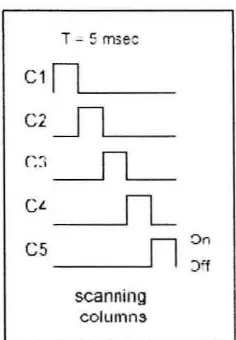
If we put 1.8 Volt for an example at the lines 4 and I 0, the LED will lit, the
trick of multiplexing is to scan the columns (5) and set the data on the rows (7) or
visa-versa, and the multiplex-frequency must be greater than approximate. 40Hz else you will see the flickering of the LEDs to much. It takes about 5 msec per column,
that's about 25 msec for one frame.
The scanning goes as follows, first set the rows data on the 7 rows e.g.
l 0 I 0010, then activate (0 or I -> depends on which type CA = common cathode, or
CC =common anode) the first column. now these LEDs (dots) will lit wait 5 msec,
then switch the column off, now load the next rows data, and set the second column on, wait 5 msecs again, and switch it off again, if this sequence repeat very fast, the data (character data) appear on the display (refresh frequency 40-70Hz).
[image:19.545.93.499.90.255.2]6
' - - - -
-The 74HC595 is an 8-bit shift-register IC, with this IC you can shift 8 bits to
the outputs with only 3 wires, that are Data (Ds), and 2 shift inputs (SHcp, STep). connect like the diagram.
2.1.2 Type of Display
The trick to scroll a character across the display is to build one character on
the display by scanning the columns very fast. and let say each 20 times (20 frames) scroll it one position to the left, this will give the effect of a walking text across the
dot-matrix display. So first build one frame, repeat this 20 times, and after that, read
the data one address later, if we do this 5 times (5 columns) the character scroll from
7
registers IC's, that are 5 x 8 bit= 40 bits I 5 columns= 8 dot-matrix displays. making it a nice tiny message sign.
This is simple stroller formula:
adrs = counter + pointer [I]
'adrs' is the register which will read the address to fetch data from, 'counter' is a bit-counter which counts up from 0 to 4 (5 columns), and 'pointer' is the register
which increases every so many frames. The program starts from zero, so 'counter'
and 'pointer' are both zero in the first round, so the first Rows data for the 1st column
will be fetched from the 1st address (0). When small routine increase with one after 'counter' resets to zero, at that moment one frames is build (1 image= 1 character) and count that. The next round 'counter' will go to I, and so 'adrs' will be also I
because 'pointer' only increases each lets say 25 times (25 frames), so after 25 times 'pointer' increases with one, and then the flfst round will be: adrs = 0 + 1 = I, the second round that will be 2, so you see the reading from the address is shifted one
position to the left, because you INC. You can also scroll backwards, simply DEC the routine where 'pointer' is counted each 25 frames. Make the whole sequence run
at a speed of about 25 msec that will make the display refresh at 40Hz.
2.1.3 The full intensity of the displays
T- 5 mse~
C1n.___ _ _
C2
__Il__
C::1
__f1_
CL_f1_
cs
n
~n· :.Yf
scanning
[image:22.548.243.361.87.257.2]columns
Figure 2.3 : The duty cycle of each LED
8
But the On I Off time of each dot is 5 msec ->On for 5 msec, so thafs only 511000th
of a second. Here is the formula to know how much current is needed to have the
same light-intensity:
l-Ied = T -tot I On-time
*
Normal Current [2]Where T-tot =the time from one rising edge to another.
On-time = the time that the LED is actually on.
Normal Current= the current the LED can handle at DC
2.2 Common configuration
1. Stand alone keypad solution
11. On-to-one Serial Short Distance RS232 solution
iii. One-to-many serial RS422 solution
iv. LAN/Ethemet solution
v. Wireless- LAN solution
9
2.2.1 RS232
Communication between the software and the message board will be done via
the RS232 serial port on the computer. The RS232 port has 9 pins. Three pins are
used for communicating with the PC, one for receiving, transmitting, and ground.
The remaining six pins are address pins for addressing more than one receiver, which
will be flXed in our case since there is only one receiver. The computer program will
send the data serially to the transmit pin, and will monitor the receive pin for a
conformation message. Messages being received will be preceded with a specified
preamble of 8 bits to ensure that noise is not interpreted as a message.
2.3 Device Overview
There are many types of devices and components can be use for constructing
this message board system. In this system, the main devices and components is
consists of display device and main controller.
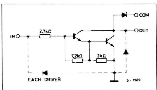
2.3.1 ULN2803
The ULN2803 each contains eight Darlington transistors with common
emitters and integral suppression diodes for inductive loads. Each Darlington
10
IN
,
IN 2. z
IN 3 ~ IN 4 4
IN 5 5
IN 6
IN
,
IN
•
[image:24.550.191.428.88.284.2] [image:24.550.170.428.353.501.2]ONO
Figure 2.4 : ULN2803 internal circuit
~ 0Cot4
i-7kr. -,--oour
rC
INO t l J
'
I~
7.21afi
...
C_l
L t4
--
--
-
1-
J~
-
I'W4
LtoCti OOIVER
Figure 2_5 : Schematic diagram and Order Codes
2.3.2 PIC18F452
These devices come in 28-pin and 40/44-pin packages_ The 28-pin devices do
not have a Parallel Slave Port (PSP) implemented and the number of