IMPULSE VOLTAGE GENERATOR :
TRIGGERING CIRCUIT
Khairul Ridzuan Bin Mohamad Zin
Bachelor of Electrical Engineering
(Industrial Power)
v
“ I hereby declare that I have read through this report entitle “impulse
voltage generator : triggering circuit” and found that it has comply the
partial fulfillment for awarding the degree of Bachelor of Electrical Engineering (Industrial Power) ”
Signature :………..
Name of supervisor : ……….
iii
IMPULSE VOLTAGE GENERATOR:
TRIGGERING CIRCUIT
KHAIRUL RIDZUAN BIN MOHAMAD ZIN
A report submitted in partial fulfillment of the requirements for the degree
of Electrical Engineering (Industrial Power)
Faculty of Electrical Engineering
Universiti Teknikal Malaysia Melaka (UTeM)
iv
I declare that this report entitle “impulse voltage generator : triggering circuit” is the
result of my own research except as cited in the references. The report has not been accepted for any degree and is not concurrently submitted in candidature of any other degree.
Signature :………
Name : Khairul Ridzuan Bin Mohamad Zin
vi
ACKNOWLEDGEMENT
First of all, I‟m express my deepest thank and gratitude to Allah SWT who gave me spirit and soul throughout the duration of my final year project.
I am deeply indebted to my supervisor Mr Aminudin Bin Aman from the Universiti Teknikal Malaysia Melaka, stimulating suggestions and encouragement helped me in all the time of research for and writing of this thesis.
Finally, I would like to dedicate my gratitude to my parents, lecturers and staff of Electrical Engineering Faculty, Universiti Teknikal Malaysia Melaka, and my classmates from 4 BEKP and who helped me directly or indirectly in the completion of this project. Their encouragement and guidance mean a lot to me. Their sharing and experience foster my belief in overcoming every obstacle encountered in this project.
vii
ABSTRACT
viii
ABSTRAK
ix
TABLE OF CONTENTS
CHAPTER TITLE PAGE
DECLARATION iii
ACKNOWLEDGMENT iv
ABSTRACT v
ABSTRAK vi
TABLE OF CONTENTS vii
LIST OF TABLES x
LIST OF FIGURES xi
LIST OF SYMBOL xiii
LIST OF APPENDIX xiv
1 INTRODUCTION 1
1.1 Background 1
1.2 Problem Statement 2
x
1.4 Scope of Project 2
1.5 Project report outline 3
CHAPTER TITLE PAGE
2 LITERATURE REVIEW 5
2.1 Introduction 5
2.2 Lightning 5
2.2.1 Lightning Phenomenon 6
2.2.2 Type of Lightning 7
2.3 Impulse Voltage Generator 7
2.3.1 Lightning impulse waveform 8
2.3.2 Parameter of Impulse Voltages 11 2.3.3 Impulse Voltage Generator Circuit 12
2.4 Ignition coil 14
2.4.1 Operating Principles 17
3 METHODOLOGY 19
3.1 Introduction 19
3.2 Flow Chart of Methodology 20
3.2 Literature Research 21
3.3 Software design 22
3.3.1Circuit Design of Impulse Voltage Generator 22
3.3.2 Circuit simulation 23
3.4 Hardware design 24
3.4.1 Circuit setup 24
3.4.2 Hardware setup 26
xi
3.4.4 Spark rod 29
3.4.5 Stand for spark rod 30
3.4.6 Power supply 31
CHAPTER TITLE PAGE
4 RESULT OF ANALYSIS 33
4.1 Introduction 33
4.2 Safety precaution 33
4.2.1 General safety 34
4.2.2 Special Rules of Caution 35
4.3 Preliminary experiment 37
4.3.1 Primary winding test 38
4.3.2 Secondary winding test 38
4.4 Circuit Test 40
4.4.1 Result of analysis 42
4.5 Result of experiment 46
5 CONCLUSION AND DISCUSSION 53
5.1 Introduction 53
5.2 Conclusion 53
xii
LIST OF TABLES
NO TITLE PAGE
3.1 List of component 25
3.2 List of support component 27
4.1 Bench testing for ignition coil 39
4.2 Observation of experiment 32
xiii
LIST OF FIGURES
NO TITLE PAGE
2.1 Lightning strike 6
2.2 Type Circuits for producing impulse voltages 8
2.3 Full wave lightning impulse voltage 9
2.4 Chopped lightning impulse voltage 10
2.4(a) Impulse chopped at tail. 10
2.4(b) Impulse chopped at front 10
2.5 General waveshape of impulse 12
2.6 Basicequivalent circuit impulse generator. 13
2.7 Ignition coil sketching 14
2.8 Inside ignition coil 16
2.9 Autotransformer schematic 17
3.1 Flow chart 20
3.2 Ignition coil driver circuit 22
3.3 Simulation circuit using multisim10 23
3.4 Basic diagram to produce spark 24
3.5 Ignition coil driver diagram 25
3.6 Setup circuit 26
3.7 Wood 27
xiv
3.9 Custom sphere gap 29
3.10A Steel rod 30
3.10B Steel rod 30
3.11 Stand holder for the spark gap 30
3.12 sketch illustration of spark gap 31
3.11 Function generator 31
3.12 Accumulator 32
3.13 Set of impulse generator 32
4.1 Ignition coil 37
4.2 Primary resistance test 38
4.3 Secondary resistance test 39
4.4 Setup test using functional generator 41
4.5 Experiment using function generator 41
4.6 Setup experiment using battery 43
4.7 Digital phosphor oscilloscope 44
4.8 High voltage probe 44
4.9 Setup experimental 45
4.10 Before flashover 47
4.11 After flashover 47
4.12 Finest waveform of impulse 48
4.13 Graph scale 48
4.14 Determination of T1 49
4.15 Fall time measurement 50
4.16 Scale for rise time 51
4.17 Scale for tail time 52
REFERENCES 56
APPENDIX A 57
xv
LIST OF SYMBOLS
A Ampere
mA Miliampere
AC Alternate current
DC Direct current
R Resistor
C Capacitor
L Inductor
I Current
V Voltage
kV Kilovolt
µs Microsecond
µF Microfarad
pF Pikofarad
Ω Ohm
K Kilo
Hz Hertz
cm Centimeter
mm Milimeter
Vp Peak voltage
xvi
T2 Tail time
LIST OF APPENDIX
APPENDIX TITLE PAGE
A Other impulse waveform 57
xvii
CHAPTER 1
INTRODUCTION
1.1Background
This project was proposed develop an impulse voltage generator triggering circuit in range of 2 kV. This project can be use for surge protector device (SPD) experiments that involving low voltage impulse because the existing impulse generator is not suitable for low voltage SPD testing cause of its voltage rating. Sensitivity also issues on conducting the test on low voltage SPDs in term of the sphere gap adjustments.
xviii
1.2Problem Statement
The behavior of lightning consists of direct and indirect. In order to develop the artificial lightning, the impulse voltage generator is used besides adjusting the sphere gap. Besides that, triggering circuit must be built too as to easier to catch the flashover. Without this triggering circuit, flashover is producing itself automatically between two sphere gaps and some time continuously trigger. To catch the wave with this development of triggering circuit, difficulty could be overcome.
1.3Objective
The objective of this project is been text as below:
1. To create an artificial lightning by using impulse voltage generator.
2. To develop a triggering circuit for in range of 2kV impulse voltage generator. 3. To determined impulse fine shape.
1.4Scope of Project
In order to achieve this project objective, the following scopes will be covered:
1. The scope of this project is to generate flashover in range 2kV 2. Use a sphere gap as a triggering device.
xix
1.5 Project report outline
For this project, its generally divide into 5 chapter which is consist;
Chapter 1: Introduction
Chapter 2: Literature Review
Chapter 3: Methodology
Chapter 4: Result of analysis
Chapter 5: Conclusion and Recommendation
For introduction, chapter 1 is a general overview of the research project, the problem statement, objective and scope of research project are defined. The research project that will be done are based on the objectives and scopes that been stated earlier.
In chapter 2, its presents the literature review and theory background. In this chapter the principle and phenomenon of lightning, studies related with the theoretical impulse voltage, waveshape of impulse, related circuit. The study also related with ignition coil or autotransformer where cover up general knowledge, operation of ignition coil. Studies on literature review helps in understanding the fundamental of voltage surge and the operation of impulse voltage.
xx
In chapter 4, the major parts of the experimental work and analysis were explained here. The general safety precaution, experimental works, experimental and result of analysis. In order to obtain the experimental data will be discussed in detail.
xxi
CHAPTER 2
LITERATURE REVIEW
2.1 Introduction
This section will discuss about the previous study that related in project, impulse voltage generator with triggering circuit. In this section, the explanation about lightning phenomenon has been study also with related circuit and characteristic of impulse. For the experimental research about ignition coil or transformer is been cover too.
2.2 Lightning
xxii
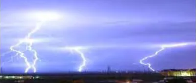
Figure 2.1: Lightning strike
M.A.Uman [1] has made a conclusion from his research of lightning and state that many “Cumulonimbus” cloud produces a light. Lightning is a discharge of electric static occur in cloud, it, s because in cloud already have negative and positive charges. Lightning that have been occurring is categorized as lightning between cloud and earth. Lightning cloud to earth can make harmful to human and others property. It parameter include amplitude voltage, current, time delay and others. Negative lightning can produce 3 or 4 impulse for every strike and delay time between impulse is 20 ms.For positive lightning, it does seldom occur.
2.2.1 Lightning Phenomenon
xxiii
malfunction of sensitivity electronic equipment, it‟s essential to evaluate the lightning electromagnetic environment in order to mitigate its effect and improve the power system quality”[2]
2.2.2 Type of Lightning
There are various ways by which lightning can disturb low voltage line [2.]Basically lightning consist direct and indirect lightning. Direct lightning occurs when there is a storm. Direct lightning is dangerous because it can kill a human. Indirect lightning occurs from the propagate wave of direct lightning. Its mean that it‟s less powerful than direct lightning. Indirect lightning commonly occur in communication line through induction [3].
2.3 Impulse Voltage Generator
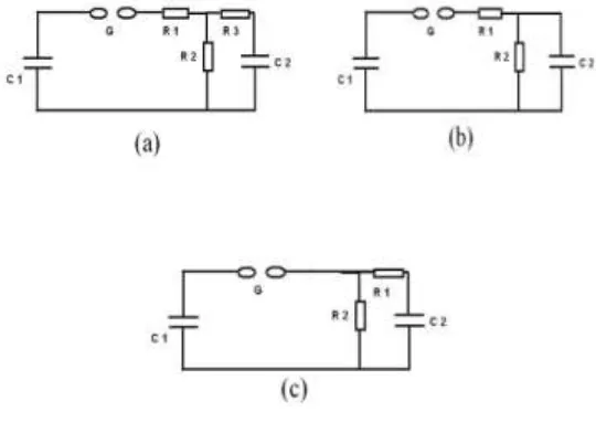
A double exponential waveform may be simulated in the laboratory with a combination of a series R-L-C circuit under over damped conditions by the combination of two R-C circuits. Capacitor C1 previously charged to a particular dc voltage is suddenly discharged into the wave-shaping network by the spark gap (G). The discharge voltage V0 (t) across C2 (test object) gives rise to the desired double exponential wave shape.
xxiv
[image:23.612.196.466.126.322.2]the load capacitance C2. The value of the circuit elements determines the shape of the output impulse voltage.
Figure 2.2: Type Circuits for producing impulse voltages
2.3.1 LIGHTNING IMPULSE WAVEFORM
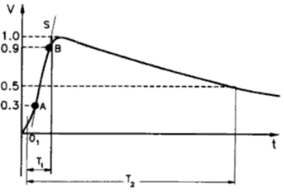
A single, unipolar voltage pulse is term of an impulse voltage. The duration of the impulse voltage base upon the method of the generation. The various national and international standards define impulse voltages as a unidirectional voltage which rises more or less rapidly to a peak value and then decays relatively slowly to zero [3].
xxv
Figure 2.3: Full wave lightning impulse voltage