University of Southern Queensland
Faculty of Health, Engineering and Sciences
Arduino Modbus Simulator
A dissertation submitted by
Ryan Beccarelli
In fulfilment of the requirements of
ENG4112 Research Project
Towards the degree of
ii Abstract
Modbus is an industrial communications protocol used to interconnect control systems and control system input / output equipment such as sensors and transducers. It is platform independent and is commonly used to network control systems from different manufactures. A purpose of the interconnection is to allow data to be stored centrally for analysis and to allow remote control of package control systems by a master system. While Modbus is commonly used, there are a limited number of diagnostic tools and solutions for use by technicians.
This dissertation documents the software and hardware design of an Arduino microcontroller based Modbus simulator to give end users such as technicians and engineers a new tool to use for commissioning and troubleshooting Modbus networks. The outcome of this project is a working Arduino Modbus Simulator prototype, that has been successfully tested with industrial control systems.
Benefits delivered by the project can be summarised into three areas being:
1. Reducing the Mean Time to Repair of a Modbus serial communication link 2. Ergonomic and simple to use alternative to computer based systems
iii University of Southern Queensland
Faculty of Health, Engineering and Sciences
ENG4111/ENG4112 Research Project
Limitations of Use
The Council of the University of Southern Queensland, its Faculty of Health, Engineering & Sciences, and the staff of the University of Southern Queensland, do not accept any responsibility for the truth, accuracy or completeness of material contained within or associated with this dissertation.
Persons using all or any part of this material do so at their own risk, and not at the risk of the Council of the University of Southern Queensland, its Faculty of Health, Engineering & Sciences or the staff of the University of Southern Queensland.
iv University of Southern Queensland
Faculty of Health, Engineering and Sciences
ENG4111/ENG4112 Research Project
Certification of Dissertation
I certify that the ideas, designs and experimental work, results, analyses and conclusions set out in this dissertation are entirely my own effort, except where otherwise indicated and acknowledged. I further certify that the work is original and has not been previously submitted for assessment in any other course or institution, except where specifically stated.
v Acknowledgements
A special thanks goes to my supervisors, Mrs Catherine Hills and A/Prof Alexander Kist, for their valuable time in providing guidance during the execution of this project.
I would also like to thank all the USQ faculty that have guided me over the years of my study. It has been a challenging time for me and I appreciate all help that has been given.
Finally, thank you to Caitlin and Alex, for your patience and always supporting me on this journey.
RYAN BECCARELLI University of Southern Queensland
vi Contents
Abstract i
Acknowledgements v
List of Figures ix
List of Tables x
Nomenclature xi
1. Introduction ... 1
1.1. Modbus and Process Control Systems ... 2
2. Literature Review and Modbus Software Hardware Review ... 4
2.1. Modbus Introduction ... 4
2.2. Modbus Physical Layer – Serial ... 6
2.2.1. RS-232 ... 6
2.2.2.RS-485 ... 7
2.3.Ethernet ... 7
2.4.Modbus Data Link Layer ... 7
2.5.Modbus Application Protocol ... 8
2.6.Error Checking ... 9
2.7.Survey of Existing Installations ... 9
2.8.Proprietary Software ... 9
2.9.Open Source Software ... 12
2.10.Hardware Options ... 14
2.11.Software Testing Methodology ... 15
3. Analysis of Existing System ... 17
3.1.Invensys Triconex ... 18
3.2. Triconex Slave ... 21
3.3. Triconex Master ... 21
3.4. Allen Bradley SLC500 ... 22
3.5. SLC500 Slave ... 24
3.6.Signal Interfaces ... 25
3.7.Test Systems ... 28
vii
4.1.Microprocessor Analysis ... 31
4.2.RS-485 Serial Communication Analysis ... 33
4.3.RS-232 Serial Communication Analysis ... 35
4.4.Display ... 37
4.5.Input Keypad ... 39
4.6.Enclosure ... 40
4.7.Ancillaries ... 41
4.8.Prototype ... 42
4.9.Final Hardware Design & Assembly ... 42
5. Software Analysis and Design ... 46
5.1.Arduino Integrated Development Environment ... 46
5.2.Arduino Modbus Simulator - Master ... 47
5.3.Arduino Modbus Simulator – Slave ... 49
6. Testing ... 52
6.1.ModSim32 Slave ... 52
6.2.Invensys Triconex Slave ... 53
6.3.SLC500 Slave ... 53
6.4.ModScan32 Master to Arduino Modbus Simulator Slave ... 55
6.5.Battery Test ... 55
6.6.Incorrect Serial Connection ... 56
7. Conclusions and Further Work ... 57
7.1.Conclusions ... 57
7.2.Achievement of Project Objectives ... 57
7.3Project Benefits ... 57
7.4Further Work ... 58
References ... 59
Appendix A Project Specification ... 62
Appendix B Schematics ... 63
Appendix C Arduino Software ... 64
C.1 AMS_Master Code ... 64
C.2 AMS_Slave Code ... 101
viii
C.4 modbus.h Code ... 179
C.5 modbusDevice.cpp Code ... 180
C.6 modbusDevice.h Code ... 181
C.7 modbusRegbank.cpp Code ... 182
C.8 modbusRegBank.h Code ... 187
C.9 modbusSlave.cpp Code ... 189
C.10 modbusSlave.h Code ... 201
Appendix D User Guide... 205
ix List of Figures
Figure 1.1: Graphical representation of data communication in industrial control system………..2
Figure 2.1: Modbus communication stack………....5
Figure 2.2: Modbus Protocol – Serial Implementation and OSI stack………..6
Figure 2.3: Modbus Master requesting data from Slave………...8
Figure 2.4: Types and Number of Modbus Slaves in oil & gas installations……….9
Figure 2.5: MatrikonOPC Server for Modbus………10
Figure 2.6: Modbus RTU Master Interface……….11
Figure 2.7: Modbus RTU Slave Interface………...11
Figure 3.1: Typical Tricon Main Chassis (Planning & Installation Guide)……….18
Figure 3.2: Example Screen TCM Serial Port Configuration……….20
Figure 3.3: Tag aliased to Modbus addressing………....21
Figure 3.4: Tricon function block MBWRITE_DINT………....22
Figure 3.5: Allen Bradley SLC500……….23
Figure 3.6: Prosoft 3150-MCM………..23
Figure 3.7: 3150-MCM RS-232……….24
Figure 3.8: 3150-MCM RS-485……….24
Figure 3.9: SLC500 N7 file for MCM configuration………...25
Figure 3.10: Adam-4520 RS-232 to RS-485 converter………...25
Figure 3.11: Lantronix Xpress DR terminal server………...26
Figure 3.12: UTEK UT201 RS-232 to RS-485 converter………...27
Figure 3.13: Weidmuller DB9 Screw Terminal………..27
Figure 3.14: ModScan to Triconex………...28
Figure 3.14: Triconex to ModSim………..29
Figure 3.15: ModScan to SLC500………..30
Figure 3.16: Triconex to SLC500………...31
x
Figure 4.2: RS-485 serial hardware………34
Figure 4.3: RS-232 serial hardware………36
Figure 4.4: Display Options………38
Figure 4.5: Keypad options………....39
Figure 4.6: Enclosure Options………....40
Figure 4.7: PPT-4081 enclosure with LCD………...43
Figure 4.8: Mounting of hardware………..44
Figure 4.9: Initial wiring……….44
Figure 4.10: Wiring looms………..45
Figure 4.11: Final Hardware Design………...45
Figure 6.1: Arduino Modbus Simulator Master to ModSim32 Slave………..52
Figure 6.2: Arduino Modbus Simulator Master to Triconex Slave……….53
Figure 6.3: Arduino Modbus Simulator Master to SLC500 Slave………..54
Figure 6.4: Arduino Modbus Simulator Master to SLC500 Slave………..54
xi List of Tables
Table 4.1: Microcontroller Specifications……….32
Table 4.2: Microcontroller rankings………..33
Table 4.3: RS-485 rankings………...35
Table 4.4: RS-232 rankings………...37
xii Nomenclature
ADU Application Data Unit
ASCII American Standard Code for Information Interchange CRC Cyclical Redundancy Check
DCS Distributed Control System
FPSO Floating Production Storage and Offtake HART Highway Addressable Remote Transducer LCD Liquid Crystal Display
OPC Object Linking and Embedding for Process Control PCS Process Control System
PLC Programmable Logic Controller SIS Safety Instrumented System TCM Tricon Communication Module
TCP/IP Transmission Control Protocol / Internet Protocol TMR Triple Modular Redundant
TTL Transistor to Transistor Logic
1
1. Introduction
This dissertation documents the hardware and software solution for the Arduino Modbus Simulator. The purpose of this project is to develop and the prove the concept of a handheld Modbus serial network test tool based on the Arduino open source development platform. This dissertation provides a literature review of what Modbus is, where and how it is used and why there is a need for this project. Some of the information contained in this dissertation was previously submitted as an unpublished works assignment by the author Beccarelli, R 2015, ‘ENG4110 Engineering Research Methodology Assignment 2’, Coursework assignment, University of Southern Queensland.
The motivation for completing this project was driven by the author’s experience where an industrial control system Modbus protocol network had failed, causing both economic losses and safety concerns. There was clearly a lack of test equipment available for Modbus in comparison to what was freely available for other control system apparatus.
The aim of the project is to design and prototype an Arduino based Modbus simulator to give end users such as technicians and engineers a new tool to use for commissioning and troubleshooting Modbus networks.
Broadly the hardware and software development must satisfy the general objectives being: Hardware to be small and compact
Hardware to have easy to identify communication leads and connectors that are simple to use
Software interface is a simple design with clear instructions with the user controls Robust and reliable in both software and hardware aspects
The hardware and software application to successfully work with many different Modbus equipment manufacturers
The software and hardware solution must meet the following requirements in order to deliver a successful outcome for the project:
Hardware solution will use RS-485 as the electrical standard. RS-485 has been chosen as 2 wire solution is very common in industry, is a multi-drop connection making it very flexible for measuring voltages and testing, and available test equipment is compatible with RS-485.
The software solution will use the Modbus Remote Terminal Unit (RTU) protocol. RTU has been chosen as it is the more commonly used serial interface than the ASCII
alternative.
2 The software solution must be able to use Function Code 03 Holding Register to write to
Slave in the Double Integer format
The software solution must be able to use Function Code 04 Input Register to read from Slave in the Double Integer format.
The software solution must be able to use Function Code 02 Input Status to read from Slave in the Boolean format
The software solution must be able to use Function Code 01 Coil Status to write to Slave in the Boolean format
The software solution must perform a Cyclical Redundancy Check as its error checking mechanism.
1.1. Modbus and Process Control Systems
[image:14.595.141.455.444.680.2]Mackay (2004) describes Modbus as an industrial communications protocol that ‘has become the de facto standard in multi-vendor integration’. Modbus was invented by Modicon, now Schneider Electric, in 1979 but it still remains today as the protocol universally used to interconnect devices from different manufacturers. This is stated not only by many texts but a product search of the main automation companies such as Yokogawa, Honeywell, Emerson and Allen Bradley will reveal they offer their own propriety communication protocols for communication between its own products and they also all offer Modbus as a way of connecting their products to other manufacturers.
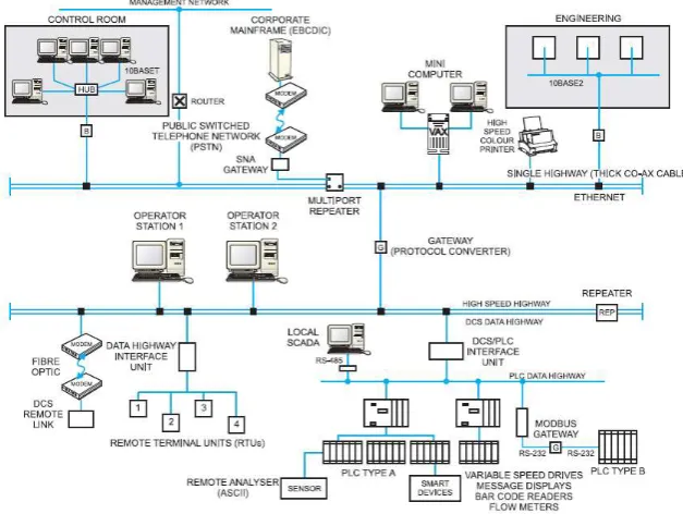
3 As represented in Figure 1.1, the integrated Process Control System can be broken into various systems. Modern manufacturing and processing facilities are controlled by an integrated Process Control System that provides remote measurement, remote transducer actuation and with control from a centralised location. The control functions can be automatic or with manual operator interaction via a computer interface.
Distributed Control System (DCS) – used as the primary process control and data acquisition system. Nodes of input and output modules controlled by central processing units (CPU) are interconnected via industrial communications network, generally a proprietary protocol.
Programmable Logic Controllers (PLC) – small and compact, with fast processing and control of input and outputs. The central processor executes the program code for control locally. Generally used for utility packages such as gas turbine controls or power management systems. The PLC is interconnected to the DCS with a communications link to allow data to be viewed in the central control room or stored in a data acquisition database for future analytic purposes.
As the DCS and PLC equipment are normally different vendors, Modbus is the protocol often used to bridge the systems, as most vendors support this communication system.
Instrumentation can be described as the sensor device or final element device. Sensors read temperature, flow, pressure, density, voltage and many other measurements. Final elements are valve actuators and positioners, motor controllers, compressor controllers, heater element controllers and many other types. Analogue sensors work by outputting a 4-20mA current signal that is proportional to the measured signal. A smart instrument transmits this data digitally, allowing for more information to be transmitted. Smart instruments connect into a PLC or DCS by what is known as a fieldbus, such as HART, Foundation Fieldbus, Profibus, DeviceNet and many other types.
Research has demonstrated that the tools available to the technicians and engineers to troubleshoot and test are not readily available or practical. For example, a field located Programmable Logic Controller (PLC) will connect via Modbus into the main facility Distributed Control System (PCS). When troubleshooting or commissioning the link is it typical for a divide and conquer approach where the PLC is disconnected and a laptop running Modbus simulation software is connected into the loop. However, a laptop is large and bulky, requires external electrical interfaces and special cables and generally has to be setup every time it is used.
4
2. Literature Review and Modbus Software Hardware Review
This section is a review of available literature for the following key concepts. 1. Modbus Introduction
2. Modbus Serial Transport Layer 3. Modbus Ethernet Transport Layer 4. Modbus Datalink Layer
5. Modbus Application Protocol 6. Error Checking
7. Survey of Existing Installations 8. Proprietary Software Options 9. Open Source Software 10. Hardware Options
11. Software Testing Methodology
2.1. Modbus Introduction
As previously discussed, Schneider Electric introduced the Modbus protocol to the market in 1979. In continuing support and development of Modbus, Schneider created a website as the central information and reference point for everything related to the protocol.
Schneider supported and maintained the Modbus site in the past but understanding the important role Modbus has to play in the market and its use by vendors who are competitors, Schneider Electric assisted in the development of an independent developer and user community organization: The Modbus Organization.
The Modbus Organisation openly provides the Modbus Specification and Implementation Guides for use by developers. This allows developers to build the hardware and implement the software on any platform they choose, independent of using products from Schneider Electric.
The guiding documents are
Modbus over Serial Line Specification and Implementation Guide V1.02 (2006) Modbus Application Protocol Specification V1.1b3 (2012)
Modbus Messaging on TCP/IP Implementation Guide V1.0b (2006)
5 Conformance Test Specification for Modbus TCP Version 3.0 (2006)
Modbus is an application layer messaging protocol, positioned at level 7 of the OSI model, which provides client/server communication between devices connected on different types of buses or networks.
Modbus is a request/reply protocol and offers services specified by function codes. Modbus function codes are elements of Modbus request/reply data.
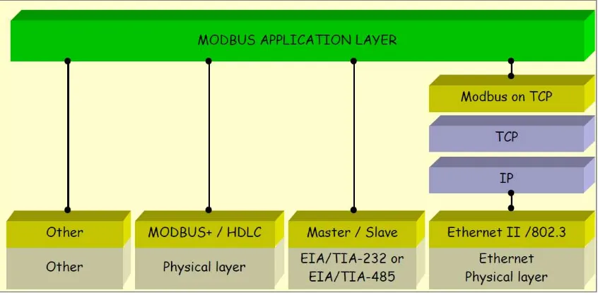
Referencing Figure 2.1 and the Modbus Application Protocol Specification V1.1b3 (2012), Modbus can be defined as “an application layer messaging protocol for client/server communication between devices connected on different types of buses or networks”
[image:17.595.87.510.314.523.2]It can be implemented using TCP/IP over Ethernet or as serial transmission over media including copper wires, fibre and radio.
Figure 2.1: Modbus communication stack (Modbus Organsiation 2015)
6 Figure 2.2: Modbus Protocol – Serial Implementation and OSI stack (Modbus Organisation
2015)
2.2. Modbus Physical Layer – Serial
Serial data is transmitted electrically by the following two methods, RS-232 or RS-485. RS-232 stands for Recommended Standard number 232 and RS-485 is Recommended Standard number 485. These standards are by the Telecommunications Industry Association (TIA) and can also be referred to as TIA-232 and TIA-485. The reference documents used for the literature review of serial ports including both RS-232 and RDS-485 are
Serial Port Complete (Axelson 1998)
Serial port and microcontrollers (Niemirowski 2013)
Practical Troubleshooting and Problem Solving of Modbus & Modbus Plus Protocols, a course book produced by IDC Technologies
2.2.1. RS-232
RS-232 transports signals as bits by creating a voltage potential across the transmit wire and the ground wire. A receiver device measures the potential and stores the signal as a 1 or 0.
RS-232 is a single sender, single receiver communication method. It is not possible without the addition of further electronic circuits to drive signals to multiple destinations.
While RS-232 designates there are 25 lines, wires to carry signals, most interfaces rarely support more than 9. Axelson (1998) states there are 3 essential signals for 2-way RS-232 communication being
Transmit Data also called TX Receive Data also called RX Signal Ground also called GND
Niemirowski (2013) defines voltage characteristics of RS-232 being Receiver input sensitivity +3 volts to – 3 volts
7 Maximum Transmit driver output +25 volts to -25 volts
Minimum Transmit driver output +5 volts to -5 volts
A logic 0 Space is a voltage +5 volts to +15 volts on the Transmit side to +3 volts to +15 volts on the Receive side.
A logic 1 Mark is a voltage -5 volts to -15 volts on Transmit side to -3 volts to -15 volts on the Receiver side.
2.2.2. RS-485
RS-485 has an advantage over RS-232 in that it has the ability to drive electrical signals to multiple destinations. RS-485 has another advantage as by not using the electrical common as a reference signal, it has a higher tolerance to electrical noise. RS-485 creates a voltage potential across a pair of wires and therefore any electrical noise affects both wires equally. This means the potential doesn’t change.
Niemirowski (2013) defines voltage characteristics of RS-485 being Receiver input sensitivity +200 millivolts to – 200 millivolts
Receiver input range +12 volts to -7 volts
Maximum Transmit driver output +12 volts to -7 volts
Minimum Transmit driver output +1.5 volts to -1.5 volts
In RS-485 a pair of wires transmits a small voltage and the receiver looks at a differential. If wire A is a voltage of 200mv greater than wire B, then it is considered a true condition (A logic 1 Mark). If wire B voltage is 200mv greater than wire A, then it is a false condition (A logic 0 Space).
2.3. Ethernet
Modbus communications over Ethernet is known as Modbus TCP. It uses the Modbus Application Protocol to produce a Modbus message that contained within a TCP packet, which is contained in a IP packet. Ethernet is just the electrical specification used to transmit the signal. This is explained by Practical Troubleshooting and Problem Solving of Modbus & Modbus Plus Protocols, a course book produced by IDC Technologies.
2.4. Modbus Data Link Layer
The Modbus over Serial Line Specification and Implementation Guide V1.02 (2006) specifies Modbus serial protocol is a Master to Slave relationship as per Figure 2.3 with the following criteria
There is only one master connected onto the bus
8 Slave nodes will only transmit data when requested from the master node.
A Slave node will never communicate to another Slave node The Master node executes one Modbus transaction at a time
Figure 2.3: Modbus Master requesting data from Slave (Modbus Organisation 2015)
2.5. Modbus Application Protocol
The Modbus Application Protocol Specification V1.1b3 (2012) states that at the application layer compromises of 4 main fields being
Addressing. This is the device address of the slave device
Function Code. This specifies what data transaction the Master requests the Slave to perform
Addressing rules specific that register data is addressed 0 to 65535 with four data types. The data types are Discrete Inputs, Coils, Input Registers and Holding Registers. Each data type has a unique range in the 0 to 65535 range.
Error checking is executed by performing Cyclical Redundancy Checking (CRC) on the message contents. The sending device calculates the CRC based on the contents of the message and appends value to the message. The receiving device performs its own calculation and compares result to what is in the CRC field.
These four fields are known as the Application Data Unit (ADU).
9
2.6. Error Checking
Axelson (1998) states that a receiver uses error checking to verify that all data arrived from the transmitter correctly. This can be done by sending redundant data or applying error checking bytes in the message. Modbus RTU uses the Cyclic Redundancy Code (CRC) method, which applies complex math to determine the data integrity. A simple way to describe a CRC calculation is to take the message data, convert to binary and divide by a particular value. The remainder returned is stored as the CRC. The CRC is added to end of message and transmitted. The receiver takes the message, performs the same mathematical division and compares the result against the CRC. If both are the same, the message was not corrupted in transmission.
2.7. Survey of Existing Installations
A survey of 3 different oil & gas facilities Process Control Systems (PCS) has been conducted. The 3 facilities were constructed and commissioned over a 21-year time horizon. The survey was a review against the PCS architecture drawings to provide insight to how many and what type of Modbus links with the results displayed in Figure 2.4.
Figure 2.4: Types and Number of Modbus Slaves in oil & gas installations The results from the sample group highlight some key points for consideration being
All slaves are using RTU as the Message Encoding format
The number of devices that are connected via communications link to Process Control System is growing
RS-485 is the dominant physical connection but Ethernet (TCP/IP) is gaining momentum. RS-232 is non-existent in the new facilities
2.8. Proprietary Software
There are a variety of Modbus software simulation packages available. They vary from Applications running on a Windows platform, Object Linking and Embedding for Process Control (OPC) software and software running on a hardware gateway. Some examples that been reviewed include
Wintech ModScan32
WinTech ModSim32 Matrikon OPC for Modbus
10 ModScan32 is an application that runs on a Windows PC and acts as a Modbus Master device. It can connect to a slave using serial or Ethernet communication reading and writing to data points in either RTU or ASCII message encoding. WinTech sells a single user license for ModScan32 Pro software for US$109.95.
ModSim32 is an application that runs on a Windows PC and simulates as a Modbus Slave device. It is an application that defines blocks of data points that can be read and written by a Modbus Master. It can connect by serial and Ethernet and data can be in RTU or ASCII format. WinTech sells a single user license for ModSim32 for US$84.95.
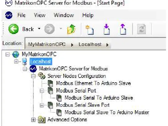
[image:22.595.162.434.294.497.2]Matrikon offers an OPC server software application that can be a Master or Slave device, connected by serial or Ethernet. Figure 2.5 displays a hierarchy tree configured with a Master Ethernet node, Master serial node and a Slave serial node.
Figure 2.5: MatrikonOPC Server for Modbus (Matrikon 2016)
Matrikon offers this product as 30 day free trial with the license cost for continuing use US$2000 for unlimited tags. This software requires a Windows Operating System and associated hardware to run.
Real Time Automation offers Modbus TCP Client, Modbus TCP Server, Modbus RTU Master and Modbus RTU Slave source code stacks. These products are written in ANSI C. They can be integrated into any hardware platform with any compiler or any operating system. There are two main integration requirements for a Modbus RTU
Connect the low level get or send character of the code stack with the microcontroller UART
11 Figure 2.6 provides an overview of the Real Time Automation Modbus Master Interface while Figure 2.7 depicts a similar structure for the Modbus RTU slave. The Modbus RTU Slave Royalty Free Source Code Stack costs US$1,295.00 and the Modbus RTU Master Royalty Free Source Code Stack costs US$1,795.00.
Figure 2.6: Modbus RTU Master Interface (Real Time Automation 2015)
12
2.9. Open Source Software
A review of open source software options freely available on the internet has been conducted focused on searching for Modbus Master and Modbus Slave examples. The results returned can be grouped into the hardware platforms required to run the software as is without porting. The hardware platforms being
Arduino
Raspberry PI Microchip PIC
Windows Applications
By completing a review of the Arduino website code examples for Communications, an example Modbus Master titled “ModbusMaster” is available. This library has been released under the GNU General Public License. A review of the features of this code indicates it has the ability to use RTU protocol over RS-232 or RS-485 and has implemented the following functions
Function Code 1 Read Coils
Function Code 2 Read Discrete Inputs
Function Code 3 Read Holding Registers Function Code 4 Read Input Registers
Function Code 5 Write Single Coils
Function Code 6 Write Single Registers Function Code 15 Write Multiple Coils
Function Code 16 Write Multiple Registers
Another library listed on the Arduino example page is titled “Modbus-arduino”. A review of this library indicates it is a Modbus Slave, supporting RTU protocol over serial 232 or RS-485 and also TCP/IP via Ethernet or WiFi. It supports the following Modbus functions Function Code 1 Read Coils
Function Code 2 Read Discrete Inputs
Function Code 3 Read Holding Registers
Function Code 4 Read Input Registers Function Code 5 Write Single Coils
Function Code 6 Write Single Registers
13 Function Code 16 Write Multiple Registers
A search of the Arduino forum provides another open source library “simple-modbus”. This library offers both a Master Option, SimpleModbusMaster, and a Slave option, SimpleModbusSlave. The Master library implements the following Modbus functions
Function Code 1 Read Coils
Function Code 2 Read Discrete Inputs
Function Code 3 Read Holding Registers
Function Code 4 Read Input Registers Function Code 15 Write Multiple Coils
Function Code 16 Write Multiple Registers
The slave library implements the following Modbus functions Function Code 3 Read Holding Registers
Function Code 16 Write Multiple Registers
A further internet search reveals an option for a Modbus slave using the RTU protocol “Arduino-modbus-slave”. This library supports serial communications and implements the following Modbus functions
Function Code 1 Read Coils
Function Code 2 Read Discrete Inputs
Function Code 3 Read Holding Registers
Function Code 4 Read Input Registers
An example for a Raspberry PI Modbus Master can be found at the program-plc website. This example implements a Modbus Master using RTU protocol over RS-232 serial communication. It implemtns the following Modbus functions
Function Code 3 Read Holding Registers
Function Code 16 Write Multiple Registers
An example library for running on the Microchip PIC hardware platform called “freemodbus-v1.4”. This is a comprehensive library that offers a Modbus Master or Modbus Slave option, can use either RTU or ASCII protocol and can be implemented over RS-232 or RS-485 serial and TC/IP. It implements the following functions
Function Code 1 Read Coils
14 Function Code 3 Read Holding Registers
Function Code 4 Read Input Registers
Function Code 5 Write Single Coils Function Code 6 Write Single Registers
Function Code 15 Write Multiple Coils
Function Code 16 Write Multiple Registers
A Windows application that is available under the General Public License for use is QModBus. This application uses the PC serial port to connect to a Modbus Slave and can send commands for both RTU and ASCII protocols implementing Modbus functions
Function Code 1 Read Coils
Function Code 2 Read Discrete Inputs Function Code 3 Read Holding Registers
Function Code 4 Read Input Registers
Function Code 5 Write Single Coils
Function Code 6 Write Single Registers Function Code 15 Write Multiple Coils
Function Code 16 Write Multiple Registers
2.10. Hardware Options
Williams (2014) defines a microcontroller has at its core a processor that reads instructions from memory, performs mathematics on a arithmetic logic unit and stores variables in random access memory all while running a program. A microcontroller can be programmed using any of a wide variety of programming languages such as C, Java, Python and many more.
An Arduino, as declared by Blum (2013) is a microcontroller development platform that has been paired with easy to use programming language, based on C. There are many models of Arduino and because it is open source hardware, schematics, source code and design files are available to everybody.
The functionality of an Arduino is easily expanded by the addition of shield. A shield is an electronic circuit that plugs into the pins of the Arduino board to enhance capability by providing more complex circuitry than what is provided on the basic board.
15 The Arduino Mega has three on board Serial ports to use and will also be used during the development process.
2.11. Software Testing Methodology
There are many books dedicated to the subject of software testing. Software Testing - A Craftsman’s Approach (Jorgensen 2014) has been selected as the primary resource for this project. The book is broken into 3 parts, with part one focusing on Mathematical Context, part two on Unit Testing, and part three on Beyond Unit Testing. Topics of focus useful for the development of a testing methodology include
Basic Definitions
Test Cases
Identifying Test Cases
Specification Based Testing
Code Based testing
Levels of Testing specifying V-Model
A further reference is Testing Computer Software (Kaner, Faulk and Nguyen 1999). This book provides a good overview of testing fundamentals such as the objectives and limits of testing, software errors and the reporting and analysing of bugs. Section 2 of this reference provides a good introduction to specific testing skills including
Problem Tracking
Test Case Design Testing User Manuals
Testing Tools
Test Planning and Test Documentation
A third software testing reference is Software Testing (Patton 2006). This text provides an introduction to the testing process with specific chapter that focuses on planning including
Goals of Test Planning
High level expectations
Definitions
Defining what will and won’t be tested
16 Test strategy
Resource requirements
Test schedule Test cases
Bug reporting
Metrics and Statistics Risks and Issues
17
3. Analysis of Existing System
The purpose of this chapter is to review the functions of an existing control system using Modbus serial communication interfaces. This will be achieved by presenting an overview of the test control systems, followed by a review of how Modbus communication is implemented. In order to consider hardware and software designs for the Arduino Modbus Simulator, it is necessary to be familiar and understand how Modbus is implemented on an industrial platform.
1. Invensys Triconex 2. Triconex Slave 3. Triconex Master 4. Allen Bradley SLC500 5. SLC500 Slave
18
3.1. Invensys Triconex
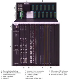
The Triconex Planning and Installation Guide describes the Tricon controller as a state of the art programmable logic and process controller that provides a high level of system fault tolerance. The guide states the system has the following features
Triple modular redundant (TMR) architecture Ability to withstand harsh industrial environments
[image:30.595.172.431.263.567.2] Allows for online input / output module replacement without disturbing field wiring Supports 118 different input / output modules including communication modules Has integral online diagnostics capabilities
Figure 3.1 Typical Tricon Main Chassis (Invensys 2015)
Triconex controllers are used as the logic solver in a Safety Instrumented System due to the high equipment reliability that comes with the hardware being Triple Modular Redundant and having onboard diagnostic capability. They are commonly used in process safety applications such as petrochemical refining, upstream oil & gas processing and nuclear reactor safeguarding.
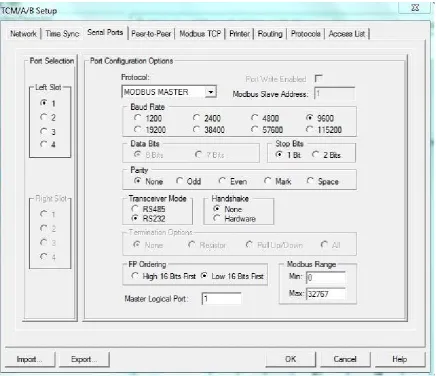
19 A Tricon TCM serial port can act as the master, slave using the following physical connection features
Point to point or multi drop network
RS-232 or RS-422 or RS-485 communication standard Half duplex (2 wire) or full duplex (4 wire) cable wiring
Parameters for setting up the serial port include
Port selection
Port Write Enabled
Protocol
Modbus Slave Address
Baud Rate
Data Bits
Stop Bits
Parity
Transceiver Mode
Handshake
Termination Options
Floating Point Ordering
Modbus Range
20 Figure 3.2 Example Screen TCM Serial Port Configuration
If using Modbus TCP, the following parameters are required for setup
Protocol
Port Write Enabled
Master Logical Port
TCP Port
Network Port
IP address
Floating Point Ordering
21
3.2. Triconex Slave
By setting the serial port on a Tricon controller as a Modbus Slave, an external Master can read tags that have been assigned Modbus addressing via an alias as displayed in Figure 3.3.
Figure 3.3 Tag aliased to Modbus addressing
Once this setup is complete, the Tricon is ready to serve as a Modbus Slave. When configuring the Tricon it must be noted that the Triconex supports Boolean, 32 bit double integers and 32 bit real numbers where the Modbus protocol supports only Booleans and 16 bit integers. This means by default for a double integer only the least significant 16 bits are transmitted and for a real number, the number must be scaled to a 16 bit integer or mapped to to 16 bit integers where one is whole number and the other is the decimal component.
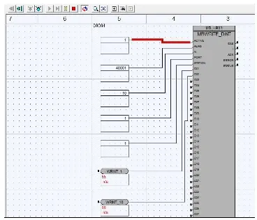
3.3. Triconex Master
When configured as a Modbus master, the Tricon needs application code as well as the serial or Ethernet port configuration. The application logic uses function blocks to execute the function code commands. The read and write function blocks are available in the Tricon library
MBREAD_BOOL
MBREAD_DINT
MBREAD_REAL
MBREAD_REAL_TRD
MBWRITE_BOOL
MBWRITE_DINT
MBWRITE_REAL
MBWRITE_REAL_TRD
The function blocks that of the data type BOOL and DINT can each transmit up to 32 data values. The function blocks of the type REAL are limited to 25 data values.
22
Starting alias which is the first Modbus register in the slave device
Number of registers to read or write
Tricon TCM serial port number that communication will occur on
[image:34.595.112.480.167.483.2] Slave ID number of the slave device
Figure 3.4 Tricon function block MBWRITE_DINT
3.4. Allen Bradley SLC500
An Allen Bradley SLC500 is Programmable Logic Controller (PLC) from the small control system suite of products from Rockwell Automation. The SLC500 has the following features
Ladder logic and structured text programming
Advanced instruction set
Built in RS-232 and RS-422 communication port on the processor
DeviceNet and ControlNet communications on selected processors
On-board ports available for Data Highway Plus (DH+) or universal remote I/O
23 Figure 3.5 Allen Bradley SLC500 (Aotewell 2016)
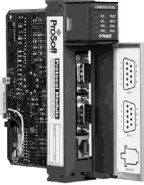
The SLC500 does not have Modbus communications capability with any processor options, but with the addition of a Prosoft communications card such as the 3150-MCM, the processor is able to read and write across the backplane to the 3150-MCM module. The 3150-MCM then communicates to the connected Modbus device. The 3150-MCM can be setup as either a master or a slave device. There are two serial ports on the 3150-MCM and they can be configured for either RS-232 or RS-485.
Figure 3.6 Prosoft 3150-MCM (Prosoft 2014)
[image:35.595.226.367.387.568.2]24 Figure 3.7 3150-MCM RS-232 (Prosoft 2014)
Figure 3.8 3150-MCM RS-485 (Prosoft 2014)
3.5. SLC500 Slave
The SLC500 is a register based control system. As such, the configuration for setting up the communications port and the Modbus definitions is done by setting registers in data table. For example, the following configuration is used to setup the SLC500 as a Modbus Slave:
N7:0 Bits 2 1 0. Set 000 to enable as RTU Slave N7:0 Bit 3. Set to 1 to allow Pass through enabled N7:0 Bit 4. Set to 0 to disable routing
N7:0 Bits 13 12. Set to 00 for one stop bit N7:0: Bits 15 14. Set to 00 for no parity
N7:1. Set integer value to 1 to set Slave address as 1 N7:2. Set integer value to 5 to set baud rate to 9600 N7:3. Set integer value to 0 to set RTS to TXD delay of 0 N7:4. Set integer value to 0 to set RTS off delay to 0
N7:5. Set integer value to 0 to set message response timeout to 0
N7:7. Set integer to 0 to allow for Modbus register 10001 or 30001 to begin at 0
N7:8. Set integer value at 10 to allow offset for function codes 01, 05, 15. To locate output image at word 100 enter 100 instead of 10 as an example. A function code 1 command with an address of zero will then start reading at 100
25 Figure 3.9: SLC500 N7 file for MCM configuration
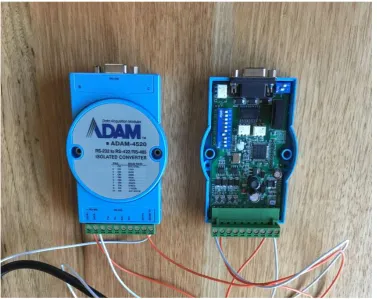
3.6. Signal Interfaces
As they are commonly used in Modbus communication links, a review and test of interface conversion hardware has been completed. As RS-485 is more tolerant to noise than RS-232, it is used on longer runs. For Modbus Master and Slave devices which only have RS-232 serial ports, RS-232 to RS-485 converters are used to change the physical connection. The Advantech Adam-4520 displayed in Figure 3.10 is one such device. It has a RS-232 DE9 connection, with RS-485 as a screw terminal connection. Baud rate is set by a series of dip switches located within the unit.
26 The RS-232 to RS-485 converters can also be used when using a standard laptop or personal computer as a simulation tool. Onboard serial ports are mostly RS-232 unless they are a special configuration. However, it is common for modern computers to not have a serial port so an option is to use a terminal server that converts Ethernet to RS-232 or RS-485. The Lantronix Xpress DR serial to Ethernet terminal is one such device. The Xpress DR is compact as displayed in Figure 3.11 but requires an external 24volt direct current power source.
Figure 3.11: Lantronix Xpress DR terminal server
27 Figure 3.12: UTEK UT201 RS-232 to RS-485 converter
A passive device used to assist in the physical network configuration was the Weidmuller DB9 to screw terminal (Figure 3.13). This din rail mountable unit was useful by using a DB9 serial straight through cable to connect to the Triconex and SLC500 serial ports, the screw terminals are then easily accessible allowing for easy serial communications configuration. For example, RS-232 on the SLC500 uses pins 2,3 and 5 with a jumper required between 7 and 8. RS-485 on the SLC500 uses pins, 9,1 & 5 with a jumper between 7 and 8. Without the DB9 screw terminal block, multiple DB9 serial cables would need to be configured. This option allows for one cable with a DB9 at one and open ended cable with the individual wires boot laced pinned which allows for flexibility in changing physical connections.
28
3.7. Test Systems
Before developing the Arduino Modbus Simulator hardware and software solution, test systems using common control systems have been implemented. The justification for doing so was to build confidence in having a working system before substituting in Arduino based prototypes. It also provides the ability to study how Modbus is implemented in different vendor software.
Four different systems were built being
ModScan Master to Triconex Slave
ModScan Master to SLC500 Slave
Triconex Master to ModSim Slave
Triconex Master to SLC500 Slave
A Modbus Master to Modbus Slave network was built using WinTech ModScan as the Master and an Invensys Triconex as the Slave (Figure 3.13). The message encoding format used in the system was RTU. The network was built and tested using RS-232 and then RS-485. When using RS-485, the UTEK UT201 RS-232 to RS-485 converter was used at the computer end of the network, while for the Triconex the same DB9 serial port is used but software selection in the Triconex enables selection between RS-232 and RS-485. Another solution for testing communication over RS-485 was completed by using the Lantronix Xpress terminal server. The Lantronix was connected to the Ethernet port of the computer running ModScan, with the terminal server being configured for Modbus RTU RS-485 connection. The Lantronix was physically wired RS-485 to the Triconex serial port which was software configured for RS-485. A test configuration for the Triconex was built using 10 holding registers and 10 coils. The Master was able to read and write to these registers.
29 A second Modbus Master to Modbus Slave network was built using an Invensys Triconex as the Master and WinTech ModSim as the Slave (Figure 3.14). The message encoding format used in the system was RTU. The network was built and tested using RS-232 and then RS-485. When using RS-485, the UTEK UT201 RS-232 to RS-485 converter was used at the computer end of the network, while for the Triconex the same DB9 serial port is used but software selection in the Triconex enables selection between RS-232 and RS-485. A test configuration for the Triconex was built using the following function blocks
MBREAD_BOOL
MBREAD_DINT
MBWRITE_BOOL
MBWRITE_DINT
The Boolean logic was setup to read 5 coils and write 5 coils. The register function blocks were setup to read 5 registers and write 5 registers.
Figure 3.14: Triconex to ModSim
A third Modbus Master to Modbus Slave network was built using WinTech ModScan as the Master and an Allen Bradley SLC500 as the Slave (Figure 3.15). The message encoding format used in the system was RTU. The network was built and tested using RS-232. A test configuration for the SLC500 was built using Modbus registers for function codes 1 to 4. As the SLC500 is a data table based controller, the Modbus address was mapped to the following N7 data table values
Write to Coils SLC500=N10:9 bits 0 to 9 ModScan=00001 to 00010
Read from Digital Inputs SLC500=N10:0 bits 0 to 9 ModScan=10001 to 10010
Write to Holding Registers SLC500=N10:20 to N10:29 ModScan=40001 to 40010
30 Figure 3.15: ModScan to SLC500
A fourth Modbus Master to Modbus Slave network was built using an Invensys Triconex as the Master and an Allen Bradley SLC500 as the Slave (Figure 3.14). The message encoding format used in the system was RTU. The network was built and tested using RS-232 at the Triconex and SLC500 but converted to RS-485 using the Adam 4520 RS-232 to RS-485 converters. This proved a RS-485 network between the two controllers which is a common industrial communications network. A test configuration for the Triconex was built using the following function blocks
MBREAD_BOOL
MBREAD_DINT
MBWRITE_BOOL
MBWRITE_DINT
The Boolean logic was setup to read 5 coils and write 5 coils. The register function blocks were setup to read 5 registers and write 5 registers. The SLC500 data table was configured with the following register setup
Write to Coils SLC500=N10:9 bits 0 to 4 mapped Modbus registers=00001 to 00005
Read from Digital Inputs SLC500=N10:0 bits 0 to 4 mapped Modbus registers=10001 to 10005
Write to Holding Registers SLC500=N10:20 to N10:24 mapped Modbus register =40001 to 40005
Read from Analogue Inputs SLC500=N10:10 to N10:04 mapped Modbus register=30011 to 30015
31 Figure 3.16: Triconex to SLC500
4. Hardware Analysis and Design
This section of the dissertation focuses on a review of the hardware options available and the strengths and weaknesses of each component relative to achieving the project goal. While the main goal of producing an Arduino Modbus Simulator is a Master, using RS-485 as the transport layer and using RTU as the message encoding format, if in achieving this minimum requirement other options are available to extend capability with zero impact to the project they were also evaluated. The hardware required to complete the requirements can be broken in the following categories
Microprocessor
RS-485 serial communications RS-232 serial communications Display
Input keypads Enclosure Ancillaries
Each component is discussed and assessed again a ranking for that component type before the final choice is documented.
4.1. Microprocessor Analysis
As part of the hardware evaluation three Arduino or Arduino compatible microcontrollers were considered during the project. As displayed in Figure 4.1 the three microcontrollers are
32 Figure 4.1: Microcontroller options
Initially an Arduino Mega 2650 was the microcontroller board used during the first prototyping. The MEGA has good memory and a lot of input / output pins options and 3 UARTs for serial communications. The downside of the MEGA option is that is has a large footprint.
The second microcontroller evaluated was an Arduino UNO. The UNO processor runs at the same speed, 16MHz, but has less memory and less input / output capacity. It is also limited to one UART. It is compact in size in comparison to the MEGA.
The third and last microcontroller tested was the Teensy 3.2. Teesny is not an Arduino product but is programmed using the Arduino IDE. The Teensy has an extremely fast processor at 96MHz, large memory, and an input / output count in between the UNO and MEGA count. The primary advantage of the Teensy is it is extremely compact with a very small footprint. The small disadvantage that the Teensy has in comparison to the MEGA and UNO is that it requires on board soldering of the connections to the input and outputs. The MEGA and UNO have the alibility for wiring to be soldered to pins before insertion into the terminals. The risk this brings to the Teensy is excessive heat on the microcontroller board leading to some form of damage or cross connection between input and outputs due to poor soldering,
A summary of the specifications of each microcontroller is provided in Table 4.1
Microcontroller CPU Speed Memory Input / Output / Serial
Arduino UNO 16 MHz 8KB SRAM 4KB EEPROM 54 DIO 16 AI 3 Serial Arduino MEGA 16 MHz 2KB SRAM 1KB EEPROM 14 DIO 6 AI 1 Serial Teensy 3.2 96 MHz 64KB SRAM 2KB EEPROM 34 DIO 21 AI 3 Serial
Table 4.1: Microcontroller Specifications
33 CPU speed
Memory
Input / Output / Serial capacity Physical size
The results of the ranking are displayed in Table 4.2. From the perspective of pure hardware and not software, the Teensy 3.2 is the most suitable, followed by the MEGA with the UNO last. However, due to issues with software compatibility with library files, the Teensy was eliminated from consideration for the prototype.
Microcontroller CPU Speed Memory Input / Output /
Serial
Physical Size
Arduino UNO 2 3 3 2
Arduino MEGA 2 2 1 3
Teensy 3.2 1 1 2 1
Table 4.2: Microcontroller rankings
4.2. RS-485 Serial Communication Analysis
As part of the hardware evaluation five RS-485 serial communication hardware options were considered during the project. As displayed in Figure 4.2 the five options are
MAXUM RS-485 Integrated Circuit (Figure 4.2 top left) Altronics TTL to RS-485 board (Figure 4.2 top centre) Libelium RS-485 shield (Figure 4.2 top right)
34 Figure 4.2: RS-485 serial hardware
The MAXIM-485 integrated circuit offers both flexibility and appears to offer low footprint. However, the IC requires supporting electronic circuitry which when combined onto a small printed circuit board, grows the footprint.
The Altronics TTL to RS-485 module is slender, has all the required supporting circuitry and has screw terminal connection for the end device connection. This breakout module requires an enable pin to be pulled high to allow for serial communication to occur. While this is not an absolute requirement for RS-485 communication, this board requires that wiring modification to be completed if allowing serial communications to be automatic.
The Libelium RS-485 shield is compact, has optional screw terminal or DB9 for the RS-485 connection, and includes all supporting circuitry. However, it requires a mother shield that this is placed onto the Arduino, making the footprint four times the size.
The DFRobot RS-485 shield is not compact, only allows for the serial connection to be from one pair of designated pins and is designed to sit on top of an Arduino host. It does have all the supporting circuitry including a selector switch that determines if an enable pin is to be used or automatically pulling it high to allow communication at all times.
35 seven can be selected giving flexibility. This is valuable if using an Arduino Uno and allows the fixed UART serial port (outputs zero to one) to be used for other purposes and by using a software serial port, it can be mapped the any of the other outputs on the LinkSprite.
The initial testing used for evaluating these boards was to use two Arduino Uno’s, each with a RS-485 serial communication device, and setup one as the sender and one as the receiver. Using the SoftwareSerial function from the Arduino IDE, a simple ASCII message was sent from the sending device to the receving device and the serial monitor function included in the Arduino IDE was used to display the value on a computer connect to the receiving Arduino. All hardware options were successful.
The ranking of the RS-485 hardware is given in table 4.3. A ranking of one indicates the most suitable and a higher number is less suitable. If hardware is equal and cannot be differentiated, then an equal ranking is given.
Board Size Circuitry
Complete
Auto Enabled Flexible Connection
Maxim 3 5 2 1
Altronics 1 2 2 1
Libelium 5 3 2 3
DFRobot 2 1 1 2
[image:47.595.71.521.303.402.2]LinkSprite 4 1 1 1
Table 4.3: RS-485 rankings
The results of the ranking show that the Altronics TTL to RS-485 board and the DFRobot are the best hardware options,
4.3. RS-232 Serial Communication Analysis
As part of the hardware evaluation five RS-232 serial communication hardware options were considered during the project. As displayed in Figure 4.3 the five options are
36 Figure 4.3: RS-232 serial hardware
The MAXIM-232 integrated circuit offers both flexibility and appears to offer low footprint. However, the IC requires supporting electronic circuitry which when combined onto a small printed circuit board, grows the footprint.
The Altronics TTL to RS-232 module is compact, has all the required supporting circuitry and has a DB9 for the end device connection.
The Libelium RS-232 shield is compact, has a DB9 for the RS-232 connection, and includes all supporting circuitry. However, it requires a mother shield that this is placed onto the Arduino, making the footprint four times the size.
The DFRobot RS-232 shield is not compact, only allows for the serial connection to be from one pair of designated pins and is designed to sit on top of an Arduino host. It does have all the supporting circuitry.
37 The initial testing used for evaluating these boards was to use two Arduino Uno’s, each with a RS-232 serial communication device, and setup one as the sender and one as the receiver. Using the SoftwareSerial function from the Arduino IDE, a simple ASCII message was sent from the sending device to the receiving device and the serial monitor function included in the Arduino IDE was used to display the value on a computer connect to the receiving Arduino. All hardware options were successful.
The ranking of the RS-232 hardware is given in table 4.4. A ranking of one indicates the most suitable and a higher number is less suitable. If hardware is equal and cannot be differentiated, then an equal ranking is given.
Board Size Circuitry
Complete
Maxim 3 5
Altronics 1 2
Libelium 5 3
DFRobot 2 1
[image:49.595.185.412.273.373.2]LinkSprite 4 1
Table 4.4: RS-232 rankings
The results of the ranking show again that the Altronics TTL to RS-232 board and the DFRobot are the best hardware options.
4.4. Display
As part of the hardware evaluation three LCD display options were considered during the project. As displayed in Figure 4.4 the three displays are
38 Figure 4.4: Display Options
39
4.5. Input Keypad
[image:51.595.189.406.201.429.2]Two different membrane keypad options were considered as part of the hardware select. As depicted in Figure 4.5, a 4x3 matrix keypad and a 4x4 matrix keypad.
Figure 4.5: Keypad options
40
4.6. Enclosure
Three different hardware enclosures were considered as part of the design. A trade off between size, ergonomic feel, weight and ability to mount internally the required electronics were the factors considered. As displayed in Figure 4.6, three displays were considered being
Altronics Large
Altronics Medium
[image:52.595.170.430.293.609.2] PacTec PPT-4081
Figure 4.6: Enclosure Options
41 one hand, and didn’t have a comfortable feel. The solid edges of the unit were also not aesthetically appealing. This enclosure was sourced from a local electronics outlet.
The second enclosure was a smaller version of the first. It traded off some of the size in the attempt to find a more ergonomic and aesthetically pleasing option. The smaller unit meant it was able to held in one hand quite easily, but came the trade of came with the enclosure unable to accommodate the 128x64 LCD display. Only a 16x2 LCD screen would fit.
The third enclosure option is PacTec PPT-4081. After the initial evaluation, a suitable enclosure meeting the ergonomic and aesthetic goals could not be sourced locally, A review of what enclosures are available in a open world market was conducted. Several options were considered before deciding to purchase and trial the PPT-4081. It was a four day purchase to delivery turnaround time from Pennsylvania, United States of America to Perth, Australia. This enclosure had the smallest internal size and only allowed for a 16x2 LCD screen. It did come with a battery enclosure with simple access door. The biggest advantage of this unit is the round edges complete with a soft rubber like finish. It comfortably can be held with one hand and it has a more professional visual finish compared to the other two enclosures evaluated.
Enclosure Screen Size Internal Size Ergonomic Visual
Altronics L 1 1 3 3
Altronics M 2 2 2 2
[image:53.595.81.527.369.427.2]PPT-4081 2 3 1 1
Table 4.5: Enclosure rankings
After evaluation the PPT-4081has the best score. However, it essentially is trade off between ease of hardware design versus ergonomic feel. A factor to be considered here is that if a device is not easy to use, it will be relegated to the back of the test bench and will not be used.
4.7. Ancillaries
42
4.8. Prototype
Through the project, the Arduino Modbus Simulator prototype went through several prototyping stages. The different stages can be summarised as the following
Arduino MEGA with RS-232
Arduino MEGA with RS-485
Arduino MEGA with 4x3 keypad
Arduino MEGA with 16x2 LCD display
Arduino MEGA with LCD display and keypad
Arduino MEGA with selectable RS-232 and RS-485
Arduino MEGA with LCD, keypad, RS-232 and RS-485
Arduino MEGA with 4x4 keypad
In order to reduce footprint size, the Arduino MEGA 2650 was replaced with an Arduino Uno and the same prototype systems replicated.
The Teensy 3.2 was selected for evaluation when the project came to final design and difficulties in getting all the required hardware to fit within the selected enclosure. The Teensy prototyping was successful in a build including the LCD, keypad and both serial communication options, but an incompatibility issue with a Modbus Master library ruled it out from final system design.
4.9. Final Hardware Design & Assembly
At the completion of the hardware analysis, the final design included the following hardware Microcontroller - Arduino Uno
Display - 16x2 LCD
Input - 4x4 membrane keypad RS-485 Serial – DFRobot
RS-232 Serial – Altronics TTL to RS-232 Serial connection – 6 pin mini din
Communications selector switch – toggle double pole Power switch – toggle double pole
Potentiometer – A10K Battery – 9V D cell Enclosure – US Ergo
The circuit diagram is represented in Appendix B
43 The cut out for the LCD was done by using a Dremel disc cutter and then a 2nd cut bastard file to smooth out. The same for the keypad membrane connection, The mini din connector, switches and potentiometer were simply drilled using the right diameter drill bit. The ease of mounting this equipment in comparison to the LCD reinforced why hole and lock nut fastening was a determining factor in selecting this hardware.
[image:55.595.219.378.247.501.2]The enclosure also had some internal sockets used for mounting hardware. These were removed in order to maximise the available internal footprint but using a Dremel grinding disc to cutaway the moulded plastic plugs. Once the enclosure wad prepared the first of the hardware was mounted as represented by Figure 4.7.
Figure 4.7: PPT-4081 enclosure with LCD
44 Figure 4.8: Mounting of hardware
Once the hardware was mounted in position, the wiring connections was made (Figure 4.9). The initial looming of wires was quite easy but as the number of wires grew, the difficulty increased.
[image:56.595.210.385.440.669.2]45 Figure 4.10 shows the final wiring before it was loomed into position. Sticky squares were used along with cable ties for mounting the looms to the enclosure. Each wire also has a unique grafoplast number which makes initial wiring and trouble shooting easier.
Figure 4.10: Wiring looms
[image:57.595.151.447.507.696.2]Once the wiring was completed, the enclosure was assembled and the final outcome is displayed in Figure 4.11. The final hardware has met the hardware goal of being light, with weight of 400 grams. The unit is ergonomic and fits comfortably in one hand. The rounded edges have a soft feel and also make it aesthetical pleasing.
46
5. Software Analysis and Design
This section of the dissertation focuses on the software development that was required in order to achieve the project goals. This chapter explains the Arduino IDE, the Modbus Master library selection, the Modbus Master software configuration, the Modbus Slave library selection and the Modbus Slave software configuration
5.1. Arduino Integrated Development Environment
The Arduino language is a simple language that creates a loop that runs constantly on the microcontroller. The mandatory syntax of a valid Arduino program is as follows
void setup () { }
void loop () {
}
The setup() and loop() functions must always be present. The setup() function contains the code that is run only once by the microcontroller when the microcontroller is first powered up. The loop() function contains the code that loops forever until the power is reset or removed.
Specific libraries can be included by declaring them at the beginning program using the #include syntax.
Functions can also be added. These do not need to be declared before first using it, as they can be declared later in the program.
47
5.2. Arduino Modbus Simulator - Master
Two different software solutions have been developed using the hardware. The first acts as a Modbus Master and the second acts as a Modbus Slave. This section details the development of the Master software solution.
After conduction a review of the open source libraries available for a Modbus Master including basic testing of functionality, an open source library ModbusRtu has been selected. ModbusRtu is freely available via GitHub download. A key advantage of using this library is it allows the Modbus serial communication to be executed using the SoftwareSerial library. This library replicates the functionality of the UART, allowing any digital pins on the Arduino to be used for serial communication. The main benefit this offers is allowing the native serial communication port, pins 0 and 1 on an Arduino Uno, to be used with the serial monitor application that is built into the Arduino IDE. The native serial port is connected to the USB connection which allows the serial monitor program to be used for troubleshooting during the software development process. The program for the Modbus Master has been written in the Arduino IDE. The program structure can be broken down into the following sections
Include Libraries
Declaration of Variables
Setup Code (ran once upon power initialisation) Main Code (ran in a continuous loop)
Keypad Operation (a function called when the keypad is activated
There are four libraries used in this program being ModbusRtu
SoftwareSerial Keypad
LiquidCrystal
ModbusRtu allows for communicating with Modbus devices using the serial interfaces, RS232, RS485 and USB, via the RTU message encoding protocol. It provides the query structure that allows the Master to generate the query using the correct fields matching the Modbus specification. As previously discussed, the SoftwareSerial library allows for serial communication on any digital pins besides those directly connected to an onboard UART. This library is inherent to the Arduino IDE.
Keypad is an open source library that provides an event listener for a matrix keypad. It primarily uses functions to listen for changes of state of keypad buttons and returns this new state.
48 The program specification has been written that to comply with design, ten instances of each data type is used. The telegram function of the Modbus library, only allows for data type being unsigned16 bit integers. Therefor to allow for the digital data types, coils and digital inputs, unsigned 16 bit integers have been declared for each coil or digital, with only one bit of each integer being used. This is acknowledged as an inefficient use of memory.
When power is first applied to the microcontroller, the setup() function is run once. This contains the code to start the serial communication via the UART to the serial monitor application, creates the Modbus object using the SoftwareSerial and initiates the LCD screen with the introduction menus.
The main function loop() will continuously loop, listening for a keypad button to be activated. If it is, the keypad() function is called. Once the keypad() function returns, a large switch case control structure controls the flow of the program. The switch case structure can be summarised with the following points
Write ten Holding Registers 40001 to 40010 using Function Code 16 Write one Holding Register 400010 using Function Code 6
Read ten Analogue Inputs 30001 to 30010 using Function Code 4
Write to ten Coils 00001 to 00010 using Function Code 5 by using FC5 in ten instances Using the serial UART, writes the value of the above variables to the serial monitor on the
connected (if connected) for troubleshooting and commissioning purposes The keypad() function listens for activation of the following keys
A B C D 0 1 2 3 5 6
If A is pressed the first Coil value, 00001 is displayed. Repeated pressing the A button will loop through all Coil values, displaying the value at that memory address until the loop is completed. The same applies for B, display Digital Input address and value, C, display Holding Register address and value, and D, display Analogue Input address and value.
If the 0 keypad button is pressed, all ten Coil addresses will be set False (0). If the 1 keypad button is pressed, all ten Coil addresses will be set True (1).