UNIVERSITI TEKNIKAL MALAYSIA MELAKA
SMART CONTROL ELECTRICAL APPLIANCES
VIA RF MODULE
This report submitted in accordance with requirement of the Universiti Teknikal Malaysia Melaka (UTeM) for the Bachelor Degree of Electrical Engineering
Technology (Industrial Automation and Robotics) (Hons.)
by
NIK AHMAD RAFIUDDIN BIN NIK LEH B071110096
890919115071
UNIVERSITI TEKNIKAL MALAYSIA MELAKA
BORANG PENGESAHAN STATUS LAPORAN PROJEK SARJANA MUDA
TAJUK: SMART CONTROL ELECTRICAL APPLIANCES VIA RF MODULE
SESI PENGAJIAN: 2014/15 Semester 2
Saya NIK AHMAD RAFIUDDIN BIN NIK LEH
mengaku membenarkan Laporan PSM ini disimpan di Perpustakaan Universiti Teknikal Malaysia Melaka (UTeM) dengan syarat-syarat kegunaan seperti berikut:
1. Laporan PSM adalah hak milik Universiti Teknikal Malaysia Melaka dan penulis. 2. Perpustakaan Universiti Teknikal Malaysia Melaka dibenarkan membuat salinan
untuk tujuan pengajian sahaja dengan izin penulis.
3. Perpustakaan dibenarkan membuat salinan laporan PSM ini sebagai bahan pertukaran antara institusi pengajian tinggi.
4. **Sila tandakan ( )
SULIT
TERHAD
TIDAK TERHAD
(Mengandungi maklumat yang berdarjah keselamatan atau kepentingan Malaysia sebagaimana yang termaktub dalam AKTA RAHSIA RASMI 1972)
(Mengandungi maklumat TERHAD yang telah ditentukan oleh organisasi/badan di mana penyelidikan dijalankan)
Alamat Tetap: PS 006 Kg Kemal,
16800 Pasir Puteh,
Kelantan
Tarikh: ________________________
Disahkan oleh:
Cop Rasmi:
Tarikh: _______________________
iv
DECLARATION
I hereby, declared this report entitled “Smart Control Electrical Appliances Via RF Module” is the results of my own research except as cited in references.
Signature : ……….
Author’s Name : NIK AHMAD RAFIUDDIN BIN NIK LEH
v
APPROVAL
This report is submitted to the Faculty of Engineering Technology of UTeM as a partial fulfillment of the requirements for the degree of Bachelor of Electrical Engineering Technology (Industrial Automation and Robotics) (Hons.). The member of the supervisory is as follow:
vi
ABSTRAK
vii
ABSTRACT
viii
DEDICATION
ix
ACKNOWLEDGEMENT
In the name of Allah S.W.T, the most gracious and merciful, praise to Allah the lord of
universe and may blessing and peace of Allah be upon his messenger Muhammad
S.A.W. First, and foremost thank to Allah for giving me wellness and ideas to do this
project. Without any of it, I surely cannot complete this project in the time given.
I would like to express my deepest gratitude towards to my project supervisor, Mr Khalil
Azha Bin Mohd Annuar and every lecturer that help and guide by giving brilliant
advices and guidance to me as well as provision of the valuable time management,
encouragement and patience during the time period to completing this project.
Last but not least, I would like to express my very thankful and send our grateful to my
entire friend and my family for the moral and financial support. Their views and tis are
useful definitely. Without all these people encouragement, support and advices this
thesis project might not be successfully carried out. To those that I forget to mention,
x
TABLE OF CONTENT
Declaration iv
Approval v
Abstrak vi
Abstract vii
Dedication viii
Acknowledgement ix Table of Content x
List of Tables xiii
List of Figures xiv
List Abbreviations, Symbols and Nomenclatures xvi
List of Appendices xvii
CHAPTER 1: INTRODUCTION 1
1.1 Project Background 1
1.2 Problem Statement 2
1.3 Project Objectives 3
1.4 Scope of Project 4
CHAPTER 2: LITERATURE REVIEW 5
2.1 Introduction 5
2.2 Ultrasonic 5
2.3 Infrared 6
2.4 Xbee 6
2.5 Radio Frequency Module 7
2.6 Applying of Microcontroller Based on RF 8
2.7 Remote Control of Multiple Street Lighting 9
2.8 Collision Analysis 9
xi
CHAPTER 3: METHODOLOGY 11
3.1 Introduction 11
3.2 Overview 11
3.2.1 Work Flow Chart 12
3.2.2 Problem Solving 13
3.2.3 Block Diagram 14
3.3 Software 15
3.3.1 Proteus 15
3.3.2 Eagle for Printed Circuit Board (PCB) 15
3.4 Hardware 16
3.4.1 Transmitter 16
3.4.2 Process (Receiver) 18
3.4.3 Process 20
3.4.4 Output Relay 5V 21
3.4.5 Light-Emitting Diode (LED) 22
3.4.6 Liquid-Crystal Display (LCD) 22
3.4.7 Motor Driver L298 23
3.4.8 Magnetic Door Lock 24
3.4.9 Gas Sensor (MQ-5) 24
3.4.10 Temperature Sensor (DS18B20) 25
3.5 System Operation 26
CHAPTER 4: RESULT & DISCUSSION 27
4.1 Introduction 27
4.2 System Overview 28
4.3 Hardware Testing 30
4.4 The Relationship Between The Lengths of Antenna Against Length of Data
Transmits 33
4.5 Operating Voltage Versus Distance of Transmit Data 34
CHAPTER 5: CONCLUSION & RECOMMENDATION 38
5.1 Conclusion 38
xii
5.3 Potential Commercialization 39
REFERENCES 40
xiii
LIST OF TABLES
Table No. Title Page
3.1 Characteristic of RF Module 315 MHz 16
4.1 4.2
4.3
Result from LCD Display
Result of Length of Antenna Between Maximum and Minimum Distance Transmitter and Receiver to Operate
Result Distance Data Transmitted by Induced Different Operating Voltage
30 33
xiv
LIST OF FIGURES
Figure No. Title Page
1.1 Distance Between Switch and Door 2
1.2 Actual View of Control, Instrumentation & Mechatronic Lab 3
2.1 Conceptual Architecture Overview 7
2.2 Transmitter and Receiver 7
2.3 2.4 2.5
Circuit Diagram
RF Channels is Changed (Theoretical)
Load is Varied (Theoretical) 8
9 10
3.1 Flow Chart of Work Progress 12 3.2 3.3 3.4 3.5 3.6 3.7 3.8 3.9 3.10 3.11 3.12 3.13 3.14 3.15 3.16 3.17 3.18 4.1 Idea Development System Operation Complete Circuit
Flow Chart of PCB Work RF Transmitter Module
Transmitter and Receiver Block Diagram RF Receiver Module
The Connection for ID Pin RF Module PIC 16F877A and Pin Out
Relay Connection LCD 16x2
LCD Schematic Motor Driver L298 Magnetic Door Lock Gas Sensor
Temperature Sensor
Flow Chart of System Operation
Remote 4 Channel
xv 4.2
4.3 4.4 4.5 4.6 4.7 4.8
Hardware Prototype Application Door Lock
Different Length of Copper Wire
Minimum Distance Transmitter and Receiver to Operate Maximum Distance Transmitter and Receiver to Operate Installation Procedure for Transmitter and Receiver Operating Voltage Versus Distance of Data Transmits
28 29 33 34 35 35 37
xvi
LIST OF ABBREVIATIONS, SYMBOLS AND
NOMENCLATURE
RF - Radio Frequency
PCB - Printed Circuit Board LED - Light Emitting Diode LCD - Liquid Crystal Display
ID - Identification
GUI - Graphic User Interface
WPAN - Wireless Personal Area Networks PIC - Peripheral Interface Controller ASK - Amplitude Shift Keying
MHz - Mega Hertz
M - Metre
CM - Centimetre
V - Voltage
A - Ampere
DC - Direct Current
xvii
LIST OF APPENDICES
Appendices Title Page
A B C D E
Project Prototype SK40C
Block Diagram and Complete Circuit Software Programming
Size Prototype
1
1.1 Project Background
Radio Frequency (RF) is a rate of oscillation in the range of about 3 kHz to 300 GHz, which corresponds to the frequency of radio waves and the alternating currents which carry radio signals. The person who developed this method is Heinrich Hertz from Germany which is Germany physicist. The first primitive radio transmitters were built by him during his pioneering investigations of radio waves. These generated radio waves by a high voltage spark between two conductors.
By using this technology, people life will be easier and will make user satisfaction. So this paper intends to address the problem associated. RF was chosen because of its characteristic, which can penetrate most solids, low power required, receiver sensitivity, not light sensitive and can transmit data for longer range. At present, as we know the main disadvantage of RF is signal collision, it is happen because nowadays many applications used in RF device, one of them is hand phone, car key, and walkie-talkie. And the probability of signal collision will occur. This paper introduces a better alternative by proposing a method between transmitter and receiver.
2
1.2 Problem Statement
Figure 1.1 Distance Between Switch and Door
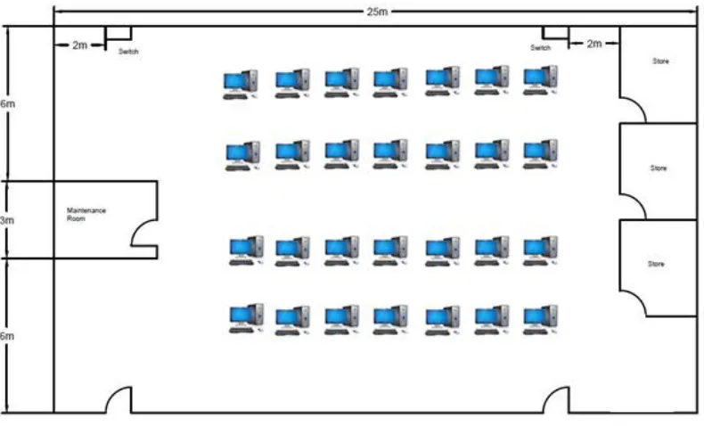
3 Figure 1.2 Actual View of Control, Instrumentation & Mechatronic Lab
In addition, Figure 1.2 show the actual view of Control, Instrumentation & Mechatronic Lab, there is a lot of equipment in the lab, such as computers and other devices. Furthermore, the spaces are really cramped to users in order to move around. In the case of negligence by the user, it can lead to accident and will lead to huge losses. The device in the lab is very expensive to purchase and repair.
1.3 Project Objectives
The objectives of this project are as follow:
(i) To design a remote control for lighting application system and fan by using radio frequency method.
(ii)To control fan speed by designing a remote.
4
1.4 Scope of project
In order to achieve the objectives of the project, the scope of this project are: Hardware system
(i) Design RF circuit. (ii)Designs relay circuit.
(iii)Develop remote control and receiver circuit.
Software system
5
2.1 Introduction
The aim of this chapter is to give the overview information about type of wireless technology nowadays. The best type of wireless is choose and suitable towards the problem identification. The comparison between all the types of wireless is done. Moreover, in this chapter, the explanations will focus more on radio frequency (RF). Nevertheless the review also discuss about the method to prevent frequency disturbance. Combination of reference from various sources such as journal, previous thesis and references book, the literature review has been carried out to collect information related to this project.
2.2 Ultrasonic
Adler, et al, (1982), explains about how to make an Ultrasonic Remote Control for Home Receivers. Electromagnetic signaling systems can be designed to bridge the short distance involved, but their signals do not remain confined between the walls of buildings or apartments. Because the distance between receivers in adjacent apartments may easily be less than the viewing distance in a single large home, individual receivers must operate on different frequencies this is inconvenient in manufacture and installation.
6
2.3 Infrared
Maureen Kaine-Krolak, et al, (1995), studies about infrared to make an Introduction to Infrared Technology, Applications in the Home, Classroom, Workplaces and Beyond. Infrared technology increasingly present in mainstream applications, but there is several disadvantage by using the method, receiver and transmitter must be almost directly aligned. Main problem is the signal will lose if blocked by common material, people wall, plant and etc.
2.4 Xbee
Gill, K, et al, (2009), created about a Zigbee-Based Home Automation System. A ZigBee based home automation system and Wi-Fi network are integrated through a common home gateway as shown in Figure 2.1 . The home gateway provides network interoperability, a simple and flexible user interface and remote access to the system. This system demonstrates the feasibility and effectiveness of the proposed system. The ZigBee (IEEE 802.15.4) is a new technology that permits the implementation of Wireless Personal Area Networks (WPAN). It is very suitable for wireless sensor networks due to the very low power consumption. System allows home owners to monitor and control connected devices in the home, through a variety of controls, including a ZigBee based remote control, and any Wi-Fi enabled device which supports by Java.
7 Figure 2.1 Conceptual Architecture Overview
2.5 Radio Frequency Module
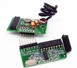
Maureen Kaine-Krolak, et al, (1995), studies about infrared to make An Introduction to Infrared Technology, Applications in the Home, Classroom, Workplace and Beyond. RF receiver and transmitter as shown in Figure 2.2 can communicate without line of sight. The signal also cannot block by any material. In addition, it can use for long range application. They also highlighted that RF is better than IR because radio recurrence vitality wave superimposed upon an infrared vitality wave and outlines the backwards relationship between recurrence and wavelength. The infrared vitality wave finishes almost 5 and a half cycles in the time that the radio recurrence wave finishes 2 cycles.
[image:23.595.222.357.600.720.2]8
2.6 Applying of Microcontroller Based on RF
Aru, O.E, et al, (2013), research about Design Exploration of a Microcontroller Based RF Remote. The PIC microcontroller family is manufactured by Microchip Technology Inc. Currently; they are one of the most popular microcontrollers, used in many commercial and industrial applications. Over 120 million devices are sold each year. The PIC microcontroller architecture is based on a modified Harvard RISC (Reduced Instruction Set Computer) instruction set with dual – bus architecture, providing fast and flexible design with an easy migration path from only 6 pins to 80 pins and from 384 bytes to 128 Kbytes of program memory.
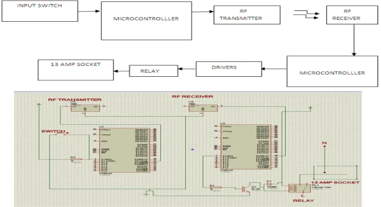
[image:24.595.110.494.520.729.2]Balasubramaniam, et al, (1992), design of Microprocessor based multifunction relay switching [home automation]. Implementing microcontroller based on RF provides a more flexible and functional alternative to the current commercial systems in controlling electronic devices as shown in Figure 2.3. The author state that the project consists of microcontroller interfaced with” KYL-500S” micro power wireless transceiver data module and connected with an electromagnetic relay which turns the switch OFF with open contact and turns it ON with closed contact. The remote control transmits radio frequency signals which are received by the receiver of the wall socket and decoded by the microcontroller which now turns the relay ON or OFF.