EXPLORING THE FAILURE MODE AND MECHANICAL PROPERTIES OF SPOT WELDED DISSIMILAR JOINTS FOR
AUSTENITIC STAINLESS AND GALVANIZED STEELS
THAM KAR MUN
SUPERVISOR DECLARATION
“I hereby declare that I have read this thesis and in my opinion this report is sufficient in terms of scope and quality for the award of the degree of
Bachelor of Mechanical Engineering (Design and Innovation)”
Signature : ………
Supervisor : DR. S THIRU CHITRAMBALAM
EXPLORING THE FAILURE MODE AND MECHANICAL PROPERTIES OF SPOT WELDED DISSIMILAR JOINTS FOR
AUSTENITIC STAINLESS AND GALVANIZED STEELS
THAM KAR MUN
This thesis is submitted to Faculty of Mechanical Engineering in partial fulfillment of the requirement for the award of Bachelor’s Degree in
Mechanical Engineering (Design and Innovation)
Faculty of Mechanical Engineering Universiti Teknikal Malaysia Melaka
DECLARATION
“I hereby declare that the work in this report is my own except for summaries and quotations which have been duly acknowledged.”
Signature : ………
Author : THAM KAR MUN
ACKNOWLEDGEMENTS
The success of this project depends largely on the encouragement and guidelines of many others. I would like to take this opportunity to express my gratitude to the people who have been instrumental in the successful completion of this report.
Firstly, I would like to express my outmost gratitude to my beloved supervisor, Dr. S. Thiru Chitrambalam. He guided me in different matters regarding my project. Furthermore, he had been very kind and patient while correcting my doubts. The supervision and support that he gave truly helped me in the progression and smoothness of my project. I appreciate his valuable information, suggestion and guidance along the process for completing this project.
In addition, I am equally grateful to my senior, Mr. Larry Long Yong Siang who was willing to spend his precious time helping me out and providing me ideas as well as advise whenever I faced any problem. Furthermore, I am very thankful to my friends, Mr. Hareshwara Ruban A/L Subramaniam, Mr. Tan Beng Hong, Mr. Sean John Matthew and Mr. Sivanyanam A/L Subramaniam. I am grateful to have their assistance, for me to have completed my tasks effectively and moreover on time.
ABSTRAK
ABSTRACT
TABLE OF CONTENTS
CHAP. TITLE PAGE
DECLARATION I
ACKNOWLEDGEMENTS III
ABSTRAK IV
ABSTRACT V
TABLE OF CONTENTS VI
LIST OF FIGURES IX
LIST OF TABLES XI
LIST OF ABBREVIATIONS XII
LIST OF APPENDIX XIII
1 INTRODUCTION 14
1.1 BACKGROUND 14
1.2 PROBLEM STATEMENT 15
1.3 OBJECTIVES 15
1.4 SCOPE 16
2 LITERATURE REVIEW 17
2.1 INTRODUCTION 17
2.2 RESISTANCE WELDING 17
2.3 RESISTANCE SPOT WELDING 18
2.4 WELDING CYCLE 19
2.4.1 Process Parameters 20
2.4.1.1 Electrode Force 21
2.4.1.2 Squeeze Time 21
2.4.1.3 Weld Current 21
2.4.1.5 Hold Time 22
2.4.1.6 Upslope 22
2.5 TENSILE SHEAR TEST 23
2.6 FAILURE MODE 24
3 METHODOLOGY 25
3.1 INTRODUCTION 25
3.2 RESEARCH METHOD 25
3.3 EXPERIMENT PROCEDURE 27
3.3.1 Material Preparation 27
3.3.2 Spot Welding Equipment 28
3.3.3 Experiment Design Selection 28
3.3.4 Welding Parameter Determination 29
3.3.5 Development of Design Matrix 30
3.3.6 Tensile Shear Test 33
3.3.7 Analyses and Mathematical Modeling 33
4 RESULTS AND ANALYSIS 34
4.1 INTRODUCTION 34
4.2 SCREENING DESIGN 34
4.2.1 Experiment Result 34
4.2.2 Screening Analysis 36
4.2.2.1 Significant Factors for Response of UTS 36 4.2.2.2 Significant Factors for Response of FM 40
4.2.2.3 Types of FM 44
4.2.2.4 Relationship between UTS and FM 45
4.3 RESPONSE SURFACE METHODOLOGY 47
4.3.1 Experiment Result for RSM 47
4.3.2 Development of Mathematical Models 48 4.3.2.1 Estimation of Coefficients of the Models 48 4.3.2.2 Checking the Coefficient for Significant 49
4.3.2.3 Final Models Development 49
5.2 SCREENING DESIGN 52 5.2.1 Significant Factors for Both Responses 53 5.2.2 Relation between Parameters and Responses 53 5.2.3 Types of FM and Relation with UTS 54
5.3 RESPONSE SURFACE METHODOLOGY 56
5.3.1 Interaction effects of parameters 56 5.3.1.1 Interaction Effect of the WC% and EF on UTS 56 5.3.1.2 Interaction Effect of the WC% and US on UTS 58 5.3.1.3 Interaction Effect of the WC% and EF on FM 59 6 CONCLUSION AND RECOMMENDATIONS 61
6.1 CONCLUSION 61
6.2 RECOMMENDATIONS 62
7 BIBLIOGRAPHY 63
LIST OF FIGURES
[image:12.595.117.529.235.776.2]NO TITLE PAGE
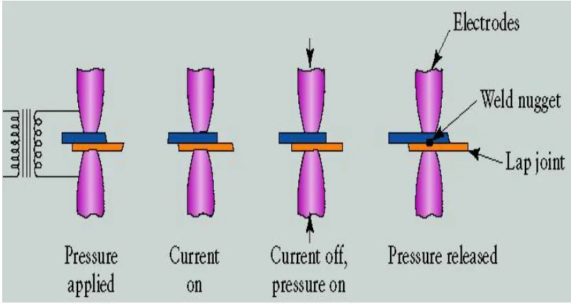
Figure 2.1 Sequence in resistance spot welding operation. 19
Figure 2.2 Cross-section view of a spot welding. 20
Figure 2.3 An illustration of electrode contact under pressure 23
Figure 3.1 Process flow for the whole project 26
Figure 3.2 Spot welded specimen under tensile shear test. 33 Figure 4.1 Pareto plot of estimate for the response of UTS. 36
Figure 4.2 Leverage plot UTS by WT 37
Figure 4.3 Leverage plot UTS by ST 37
Figure 4.4 Leverage plot UTS by US 38
Figure 4.5 Leverage plot UTS by WC% 38
Figure 4.6 Leverage plot UTS by EF 39
Figure 4.7 Leverage plot UTS by HT 39
Figure 4.8 Pareto plot for the response of FM 40
Figure 4.9 Leverage plot FM by WC% 41
Figure 4.10 Leverage plot FM by ST 41
Figure 4.11 Leverage plot FM by WT 42
Figure 4.12 Leverage plot FM by US 42
Figure 4.13 Leverage plot FM by EF 43
Figure 4.14 Leverage plot FM by HT 43
Figure 4.20 Scatter diagram for the UTS coded regression model 50 Figure 4.21 Scatter diagram for FM coded regression model 51
Figure 5.1 Contour plot of UTS vs. WC%, EF 57
Figure 5.2 Surface plot of UTS vs. WC%, EF 57
Figure 5.3 Contour plot of UTS vs. WC%, US 58
Figure 5.4 Surface plot of UTS vs. WC%, US 59
Figure 5.5 Contour plot of FM vs. WC%, EF 60
LIST OF TABLES
NO TITLE PAGE
Table 3.1 Chemical composition of AISI 304-2B and JIS G3302 SGCC
(%Wt) 27
Table 3.2 Admissible range for each parameter 28
Table 3.3 Design selection guideline 29
Table 3.4 Parameter range for screening design 30
Table 3.5 Parameters setting for RSM 30
Table 3.6 Design matrix for screening design 31
Table 3.7 Design matrix for RSM 32
Table 4.1 Data collected for screening design 35
Table 4.2 P-value for each parameter for the response of FM 40 Table 4.3 Means for Oneway Anova for the response of failure mode 46
Table 4.4 RSM design matrix and responses 47
LIST OF ABBREVIATIONS
UTeM = Universiti Teknikal Malaysia Melaka FKM = Faculty of Mechanical Engineering FKP = Faculty of Manufacturing
DOE = Design of Experiment
ANSI = American National Standard Institute AWS = American Welding Society
SAE = Society of Automotive Engineers RSW = Resistance Spot Welding
LSRSW = Low Scale Resistance Spot Welding SSRSW = Small Scale Resistance Spot Welding HAZ = Heat Affected Zone
NIST = National Institute of Standard & Technology SEMATECH = Semiconductor Manufacturing Technology FYP = Final Year Project
UTS = Ultimate Tensile Stress
FM = Failure Mode
EF = Electrode Force
WC = Weld Current
WT = Weld Time
HT = Hold Time
ST = Squeeze Time
US = Upslope
RSM = Response Surface Methodology
MT = Metal Tore failure
N = Nugget Pullout failure
LIST OF APPENDIX
NO TITLE PAGE
A Gantt chart for final year project 67
CHAPTER 1
1 INTRODUCTION
1.1 Background
Joining of dissimilar metals by welding technologies has been widely utilized in engineering practice especially in the field of automotive. Other than arc welding, resistance spot welding is also been used as a joining process in the automotive industry. Dissimilar metal welding involves the joining of two or more different metals or alloys, and the most common type is the joining of stainless steel and non-stainless steel. However, there are difficulties in joining different steel sheet due to dissimilar thermal conductivity and electrical resistivity. Spot weld with dissimilar joint such as galvanized steel and austenitic stainless steel sheets are widely been used in constructing some part of vehicles body. In this study, galvanized steel sheets and austenitic stainless steel sheets were selected as materials to be spot welded.
A few studies have been published concerning the relationship between the weld control parameters and response variables of spot-welded dissimilar metal joints (Alenius, et al., 2006). Pre-welding is often been done to obtain suitable and optimum weld nugget diameter before proceed to investigate the fatigue strength as well as obtaining the S-N curve of the dissimilar joint (Vural & Akkus, 2006) (Vural, et al., 2006). The process parameters in spot welding are weld current, electrode force, hold time, squeeze time, weld time and upslope time.
1.2 Problem Statement
The determination of appropriate welding parameters for spot welding is a very complex issue particularly in dissimilar weld joints, which often needs multiple trial runs and skill in pre-determining the welding parameters, although generally not resulting in an optimum level. The inter relationships between spot welding parameters of dissimilar joints are somehow not fully investigated in a systematic way as most of the individual parameters interact each other and produce cumulative effects on the joint performance. For spot welded dissimilar joint between Austenitic Stainless steel and Galvanized steel, very limited published literature is only available.
1.3 Objectives
1. To investigate, study and record the relationship between the process variables with ultimate tensile stress and failure mode of spot welded dissimilar joint between Austenitic Stainless Steels and Galvanized Steels.
1.4 Scope
1. To study, understand the theory and relationship between the spot weld control parameters with ultimate tensile stress and failure mode of spot welded dissimilar joints between AISI 304-2B and JIS G3302 SGCC.
CHAPTER 2
2 LITERATURE REVIEW
2.1 Introduction
This chapter introduced the basic knowledge of resistance welding and also resistance spot welding (RSW). Detail descriptions about RSW were shown in the aspect of welding cycle and process parameters. Furthermore, literature of tensile test and failure mode were also presented in this chapter.
2.2 Resistance Welding
The combination of the following laws is thought to be useful in determining the amount of heat generated in resistance welding. The laws mentioned are the Ohm’s Law and Joule’s Law.
Ohm’s Law states that:
(2.1)
Joule’s Law states that:
(2.2)
Where:
V= voltage (V) I= Current (A) R= Resistance (Ω) Q= Heat generated (J) t= Time (s)
Both laws produce the following equation:
(2.3)
2.3 Resistance Spot Welding
The resistance spot welding is been favored as joining process because of the extremely low cost, which cost only less than one cent per weld. Furthermore, the high operation speed makes it suitable for automation in high production assembly line.
2.4 Welding Cycle
[image:22.595.117.519.360.574.2]A welding cycle comprises of several discrete steps as shown in Fig. 2.1. The sequence is classified into four main steps, squeezing, welding, holding, and end. During the process of squeezing, the electrodes exert pressure on to the work pieces. Further on, the current is conveyed through the work pieces until a nugget is formed at the faying surface as shown in Fig. 2.2. Pressure is still applied to hold the work pieces when current is cut off until molten nugget cooled down into a solid nugget. At the final step, upper electrodes lifted up and leave the work pieces.
Figure 2.1Sequence in resistance spot welding operation. (Source: (Kalpakjian, 2008))
Figure 2.2 Cross-section view of a spot welding. (Source: (Kalpakjian, 2008))
Three regions are identified after the welding process, the nugget, heat affected zone (HAZ) and base metal. Pouranvari, M. et al. (2008) determined the HAZ in galvanized steel sheet is wider than the stainless steel sheet due to the higher thermal conductivity. Besides, Mural, V and Akkus, A. (2004), have found out that there is heat unbalanced in the dissimilar joint weld nugget of stainless steel and galvanized steel sheet combination. Heat unbalanced cause the formation of asymmetrical weld nugget. One of the reasons which cause this to occur is due to the different properties between stainless steel and galvanized steel. The zinc layer is also said to be one of the reason of causing asymmetrical weld nugget.
2.4.1 Process Parameters
2.4.1.1 Electrode Force
According to the study made by Kaiser, J. G. et al. (1982), the contact resistance is highly affected by the factor of pressure particularly at the initial stages of heating cycle. Higher electrode force gives a higher pressure and leads to a reduction of contact resistance at the faying surface between electrode and sheet. Thus, would reduce the temperature at the contact surface, which might reduce the occurrence of expulsion. Therefore, electrode force adjudges the maximum nugget size without expulsion while the geometry of electrode is maintained constant. However, the larger which could cause an increasing of cost consumption. On top of that, a large electrode force might also damage the electrode and lead to excessive surface indentation (Kaiser, et al., 1982).
2.4.1.2 Squeeze Time
There is not much literature about the process parameter of squeeze time. It is the time where the electrodes clamps the work piece before the weld current is pass through. It is set to slow down the application of weld current until the electrode force has reached the desired level.
2.4.1.3 Weld Current