UNIVERSITI TEKNIKAL MALAYSIA MELAKA
SIMULATION OF CUTTING FORCE DURING HIGH SPEED END
MILLING OF INCONEL 718
This report submitted in accordance with requirement of the Universiti Teknikal Malaysia Melaka (UTeM) for the Bachelor Degree of Manufacturing Engineering
(Process) (Hons.)
by
HEMA NANTHINI A/P GANESAN B051110167
910103086322
DECLARATION
I hereby declared this report entitled “Simulation of Cutting Force during High Speed End Milling of Inconel 718” is the results of my own research except as cited in
references.
Signature : ……….
Author’s Name : HEMA NANTHINI D/O GANESAN
APPROVAL
This report is submitted to the Faculty of Manufacturing Engineering of UTeM as partial fulfillment of the requirements for the degree of Bachelor of Manufacturing Engineering (Manufacturing Process) (Hons). The member of the supervisory committee is as follows.
……… Supervisor
i
ABSTRAK
ii
ABSTRACT
iii
DEDICATION
iv
ACKNOWLEDGEMENT
I would like to give my deepest appreciation to my final year project supervisor, Dr. Mohd Shahir Bin Kasim for guiding me throughout the project. In addition to that, I also would like to express my sincere appreciation to Universiti Teknikal Malaysia Melaka (UTeM) for offering this Final Year Project (FYP) as a subject. The knowledge and experience gained is extraordinary and will be very useful for my future. Above all, I wish to thank my parents and family for their unconditional love and support throughout my degree course. Last but not least, I wish to thank God for giving me excellent health and chances in completing my project as well as my degree course.
v
TABLE OF CONTENTS
Abstrak ... i
Abstract ... ii
Dedication ... iii
Acknowledgement ... iv
Table of Contents ... v
List of Tables ... viii
List of Figures ... ix
List of Equation ... xi
List of Abbreviations ... xii
CHAPTER 1 : INTRODUCTION ... 1
1.1 Background of the Project ... 1
1.2 Problem Statement ... 3
1.3 Objectives ... 4
1.4 Scopes ... 4
CHAPTER 2 : LITERATURE REVIEW ... 5
2.1 Introduction ... 5
2.2 Machining Process ... 5
2.2.1 Milling Process ... 6
2.2.2 High Speed Machining (HSM) ... 7
vi
2.3.1 Machinability of Inconel 718 ... 10
2.4 Cutting tool ... 11
2.4.1 Characteristic of cutting tool ... 12
2.4.2 Cutting tool for Inconel 718 ... 12
2.5 Cutting forces ... 14
2.5.1 Merchant’s Model ... 15
2.6 Finite Element Models (FEM) ... 16
CHAPTER 3 : METHODOLOGY ... 17
3.1 Introduction ... 17
3.2 Flow Chart of Project ... 17
3.3 Simulation Material ... 21
3.3.1 Cutting Tool ... 22
3.3.2 Workpiece ... 24
3.4 Finite Element Method (FEM) Analysis ... 26
3.4.1 Simulation Control ... 26
3.4.2 Defining the Workpiece ... 26
3.4.3 Defining the Cutting Tool ... 27
3.4.4 Mesh Type ... 27
3.4.5 Generating Mesh ... 28
3.4.6 Boundary Condition ... 29
3.4.7 Assigning Movement Control ... 30
3.4.8 Contact Condition ... 32
3.5 Simulations ... 32
vii
3.6 Compare the Results ... 34
3.7 Design of Experiment (DOE) ... 35
3.7.1 Historical Data Design ... 36
3.7.2 Analysis of Variance (ANOVA) ... 37
CHAPTER 4 : RESULT AND DISCUSSION ... 38
4.1 Introduction ... 38
4.2 Simulation of Machining ... 39
4.2.1 Entry Angle of Minimum and Maximum Force ... 42
4.3 Force Generation ... 44
4.3.1 The Cutting Parameter Effect on the Generated Resultant Force ... 46
4.4 Comparison between Simulation and Experiment ... 50
4.5 Analysis of Variance for Low Resultant Force ... 53
4.6 Optimization of Parameter Using RSM Method ... 54
4.6.1 Optimization of Resultant Force ... 55
CHAPTER 5 : CONCLUSION ... 57
REFERENCES ... 59
APPENDICES ... 65
viii
LIST OF TABLES
2.1 Composition of Inconel According to Grade (METALS, 2011) 8
2.2 Characteristic of Inconel 718 9
3.1 Gantt Chart 20
3.2 Characteristic of Inconel 718 21
3.3 Cutting Tool Geometry 22
3.4 Geometry of Workpiece 24
3.5 Set of Parameter 31
3.6 Result of Previous Experiment with Actual Cutting Process 35
4.1 The Cutting Force, Feed Force And Thrust Force Obtain Through Simulation 46 4.2 Differences Between Simulation Force and Experiment Force 53
4.3 ANOVA for Resultant Force 54
4.4 Criteria for Obtaining the Optimum Response 55
ix
LIST OF FIGURES
2.1 Milling cutters: a) Up milling, b) Climb milling, c) Edge milling, d) Detail of Face Milling Windexable Inserts - (Courtesy of J.T. Black) 7
2.2 Illustration of Depth of Cut During Machining 15
2.3 Merchant’s Orthogonal Cutting Model (Shaw, 1984) 16
3.1 Flow Chart 19
3.2 Geometry of Cutting Tool 23
3.3 Geometry of Actual Cutting Tool 23
3.4 Geometry of Workpiece with Depth of Cut 1.0m 24
3.5 Geometry of Workpiece with Depth of Cut 0.75mm 25
3.6 Geometry of Workpiece with Depth of Cut 0.5mm 25
3.7 Tetrahedral Mesh Element Constructed for the Ball Nose and the Workpiece 28
3.8 Velocity Boundary Condition 29
3.9 Heat Exchange with the Environment Boundary Condition of the Workpiece 30 3.10 Heat Exchange with the Environment Boundary Condition of Cutting Tool 30
3.11 Simulation of Machining Process of Inconel 718 33
3.12 Cutting Force Exerted on Cutting Tool In Y-Axis 34
3.13 Historical Data Design 36
3.14 Set of Parameter and Obtained Results 37
4.1 Chip Formation 39
4.2 Simulation of Material Removal 40
4.3 Graph of Thrust Force (Fz) 40
4.4 Graph of Cutting Force (Fx) 41
4.5 Graph of Feed Force (Fy) 41
4.6 Prediction of Maximum and Minimum Force 42
x
4.8 Entry Angle of Minimum Force 43
4.9 Cutting Force During Simulation 45
4.10 Graph of Resultant Force 45
4.11 Graph of Average Force Against Depth of Cut 47
4.12 Graph of Average Force Against Feed Rate 48
4.13 Graph of Average Force Against Cutting Speed 50
4.14 Ploughing Effect 52
xi
LIST OF EQUATION
xii
LIST OF ABBREVIATIONS
ap, DOC - Depth of Cut
DOE - Design of Experiment FEM - Finite Element Method Fx - Cutting Force in X-axis Fy - Feed Force in Y-axis Fz - Thrust Force in Z-axis
fz - Feed Rate
HSM - High Speed Machining
UTeM - Universiti Teknikal Malaysia Melaka
Vc - Cutting Speed
1
CHAPTER 1
INTRODUCTION
1.1 Background of the Project
Machining can be defined as a chip formation process in fabricating engineering part. Machining process is a typical way to remove a material to form into desired geometry and also shape (M.S.H. Bhuiyan 2012). Machining process can be grouped into three major types. There are turning, milling and drilling. Milling is a process of a cutting operation. The cutting operation can be performed by rotating the cutting tool whereas the work piece is clamped on a table. Then the feed operation is achieved by moving the work piece toward the cutting tool (Trent & Wright, 2000).
High speed end milling process is applied for very hard material like nickel alloys, titanium alloys and others. High speed end ball milling operation is most widely used in aerospace and also nuclear reactorparts manufacturing industry (A. Li, Zhao, Zheng, & Pei, 2011). This is due to; the parts that used in aerospace industry must have low subsurface microstructure dislocation. During the machining, there is resultant force acting on three axes (x-axis, y-axis and z-axis) which known as cutting force, feed force and thrust force on the cutting tool. The cutting force exerted is varied according to nature of machining process.
2 hardening is contributing factor in premature tool life reported by (Zhang, Li, & Wang, 2012). The other problem of machining Inconel reported is flaking problem. That is related with cyclic load exerted onto rake face of cutting tool (Qian & Hossan, 2007). Those problems are associated with cutting force.
To overcome this problem is by changing machining strategy from conventional speed to high speed machining (HSM). High speed end milling process is applied for very hard material like nickel alloys, titanium alloys and others. The machine is also used to produce a complex geometry part. High speed end ball milling operation is most widely used in aerospace and also nuclear reactor parts manufacturing industry (A. Li, et al., 2011). In general, cutting speed is consider HSM when the cutting speed beyond 5000 RPM (Leigh, Tlusty, & Schueller, 1999). However, the most reasonable definition HSM specifically for Inconel is the cutting speed is ranging between 80 – 400 m/min (Thakur, Ramamoorthy, & Vijayaraghavan, 2009). HSM was claimed improve durability of cutting tool due to ability to reduce volume of removing material, hence reduce heat generated and cutting force.
The study done by (Qian & Hossan, 2007) indicate resultant force is mostly contributed by depth of cut followed by feed rate and cutting speed. However, their study merely on experiment without simulation. From the findings, Fx is mostly contribute to the resultant force. Thus, this project is initiated to simulate the effect of cutting parameter on the resultant force and to compare with the experiment. Therefore Deform 3D software is used to simulate the high speed end milling of Inconel 718.
Then the expected results will be compare with the actual experiment result which done by previous researcher. The simulation will investigate about the cutting force, where the cutting forces are affected by several of parameter. This is explaining why the application of FEM 3D software is used in order to obtain more accurate results.
3
1.2 Problem Statement
Basically nickel alloys are known as strongest materials. This nickel alloys have higher resistance to corrosion and also to high temperature. Inconel 718 is a one of the example of a nickel-based alloy. These Inconel 718 alloys are highly resistance to heavy corrosive substances. Those properties of this alloys lead to applied widely in aerospace, gas turbine, nuclear reactor, chemical and petrochemical industries. The material that used in aerospace industry must have less surface microstructure dislocation. It is very important for the part that used in aerospace industry to have low surface microstructure dislocation (Wessel, 2004).
Inconel 718 is well known as a difficult-to-cut material, so usually there is higher cutting force acting on the Inconel 718 during the machining as compared to other less harder material (Devillez, Schneider, Dominiak, Dudzinski, & Larrouquere, 2007). The higher cutting force will cause the material to have higher surface microstructure dislocation especially in normal milling and turning machines (Thakur, et al., 2009). Therefore, the high speed machining (HSM) is introduced in order to reduce the cutting force on the cutting tool. The HSM was claimed low cutting force during the machining operation. The depth of cut, feed rate and cutting speed are those several factors which act as main parameters of machining (Soo, Aspinwall, & Dewes, 2004). These parameters are very important in machining process to obtain a good surface finish. During the machining operation of Inconel 718, several of cutting force will produce due to change in the cutting parameter. The major problem faced by machinist during HSM of super alloys is short tool life. The force acting on the cutting tool leads to short tool life. The range of cutting tool life span is between 0.5min to 90min (Huang & Liang, 2005). According to (Qian & Hossan, 2007) stated that, notch wear, pitting, chipping, flanking are associated with cutting force.
4 software and the simulation results can used to determine the most significant parameter to produce lower cutting force. It is very difficult to decide the optimization of cutting parameters in real machining process due to a lot of cutting experiments need to be executed. The simulation is run based on the real machining operation.
1.3 Objectives
1) To model the cutting process of Inconel 718.
2) To compare the parameters effect on cutting force between simulation and experiment.
3) To identify the best cutting parameter to produce lower cutting force.
1.4 Scopes
The scope of the research, including:
1) This project will focus on the dry machining only. 2) The material for work piece is just Inconel 718. 3) High speed milling machine is used.
4) The material for cutting tool only focuses the PVD coated of TiAlN and AlCrN ball nose tungsten carbide (WC- 10 % Co).
5
2
CHAPTER 2
LITERATURE REVIEW
2.1 Introduction
In this chapter, the review of pass journals is done. Literature review is essentially examined according to the sources and described to justify the statements with proof of research or study in related subject.
2.2 Machining Process
6
2.2.1 Milling Process
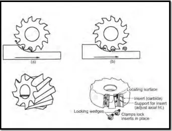
The workpiece’s material is removed away by feeding the workpiece past a rotating multiple tooth cutters is known as milling process. The fast method of machining is achieved by the many teeth’s cutting action around the milling cutting. The workpiece can be machined into various shapes like flat, angular, curved or combinations of shape. Milling process is disturbed cutting action: during every revolution, the teeth of the cutting tool is enters and exit as shown in Figure 2.1. The disturbed cutting operation is focusing the cutting tool to an impact force cycle and thermal shock on each rotation. When designing the cutting tool material and its geometry must follow these conditions (Groover, 2007).
The disturbed milling’s action produces variable thickness of chips by the tooth of the cutting tool. The milling machine will encounter problem where it face difficulty in machining further during machining the high strength material like nickel alloy, due the material hardening effect. The workpiece will be pushed rather than it cut if the cutting edge of the cutting tool is not sharp enough (H. Z. Li, Zeng, & Chen, 2006). This phenomenon will produce high cutting force.
7
Figure 2.1: Milling cutters: a) Up milling, b) Climb milling, c) Edge milling, d) Detail of face milling windexable inserts (Courtesy of J.T. Black)
2.2.2 High Speed Machining (HSM)
High speed machining (HSM) is one of the best important technologies used in advanced manufacturing. HSM is not only decreases the machining process time, it is also decreases the production cost and as well as increases the production level without the secondary process which produced a good surface finishing (Dolinsek, Sustarsic, & Kopac, 2001). The chips formation at high speed is short and thinner than the chips formed in turning process (Tschätsch, 2008).
8 maintain at lower temperature (Liao, Lin, & Wang, 2008). The other definition by Schultz & Moriwaki (1992), also mentioned that, HSM, have low cutting force, high material removal rate, and lower lead time. They also stated that the distortion in work piece is lower which resulted from the chip removal dissipation heat. This is will lead to produce a part with good surface finish and higher precision.
2.3 Inconel 718
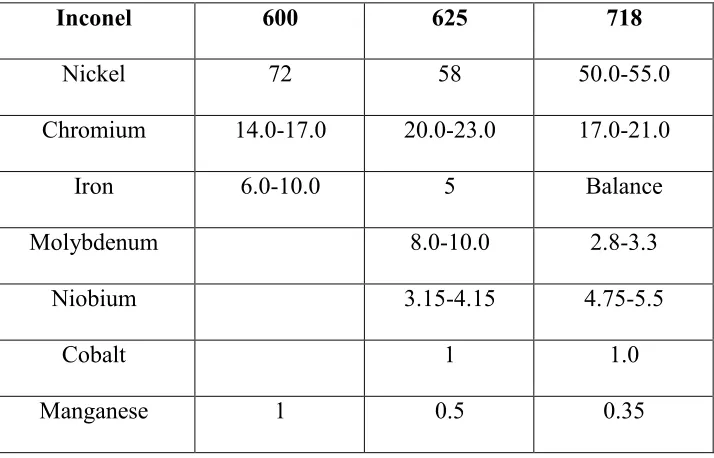
[image:23.612.151.508.461.690.2]Inconel 718 is a hardened with the nickel-chromium precipitation. It has Nickel, Iron and Chromium as main elements, little amount of Columbium, Molybdenum, Titanium and Aluminum. The Inconel 718 has higher strength without heat treatment which cause by the additional elements of niobium which reacts with molybdenum in alloy metrics hardening (METALS, 2011). The other differences in Inconel grades are the compositional dominated by nickel and chromium, which are shown in Table 2.1.
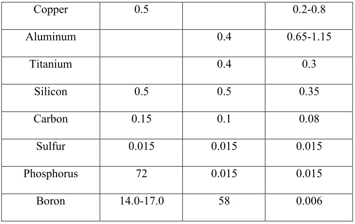
Table 2.1: Composition of Inconel according to grade (METALS, 2011)
Inconel 600 625 718
Nickel 72 58 50.0-55.0
Chromium 14.0-17.0 20.0-23.0 17.0-21.0
Iron 6.0-10.0 5 Balance
Molybdenum 8.0-10.0 2.8-3.3
Niobium 3.15-4.15 4.75-5.5
Cobalt 1 1.0
9
Copper 0.5 0.2-0.8
Aluminum 0.4 0.65-1.15
Titanium 0.4 0.3
Silicon 0.5 0.5 0.35
Carbon 0.15 0.1 0.08
Sulfur 0.015 0.015 0.015
Phosphorus 72 0.015 0.015
Boron 14.0-17.0 58 0.006
[image:24.612.146.510.70.300.2]This nickel alloy can be found in many forms like coil, bar, sheet and wire (Alloys, 2011). The properties of nickel alloy like ability to maintain the strength and ductility and also the oxidation at elevated temperature lead to use in industries of gas turbine, nuclear reactor and aerospace. The Inconel 718 was used in space ship due to its temperature which is lower than the freezing temperature (METALS, 2011). Table 2.2 shows the Inconel 718 characteristic.
Table 2.2 : Characteristic of Inconel 718
Characteristic Value
Melting point 1425 ᶱC
Thermal expansion 13 µm/m ᶱC(20-100 ᶱC) Thermal conductivity 0.15 W/cm. ᶱC
Density 8.19 g/cm 3