UNIVERSITI TEKNIKAL MALAYSIA MELAKA
DEVELOPMENT OF TEMPERATURE CONTROLLER SYSTEM
FOR QUAIL COOP APPLICATION
This report is submitted in accordance with requirement of the Universiti Teknikal Malaysia Melaka (UTeM) for the Bachelor of Computer Engineering Technology
(Computer Systems) with Honours
by
MUHAMMAD ASHWADIE BIN ZULKIPLI B071310020
880729-03-5207
UNIVERSITI TEKNIKAL MALAYSIA MELAKA
BORANG PENGESAHAN STATUS LAPORAN PROJEK SARJANA MUDA
TAJUK: DEVELOPMENT OF TEMPERATURE CONTROLLER SYSTEM FOR QUAIL COOP APPLICATION
SESI PENGAJIAN: 2016/17 Semester 1
Saya MUHAMMAD ASHWADIE BIN ZULKIPLI
mengaku membenarkan Laporan PSM ini disimpan di Perpustakaan Universiti Teknikal Malaysia Melaka (UTeM) dengan syarat-syarat kegunaan seperti berikut: 1. Laporan PSM adalah hak milik Universiti Teknikal Malaysia Melaka dan penulis. 2. Perpustakaan Universiti Teknikal Malaysia Melaka dibenarkan membuat salinan
untuk tujuan pengajian sahaja dengan izin penulis.
3. Perpustakaan dibenarkan membuat salinan laporan PSM ini sebagai bahan pertukaran antara institusi pengajian tinggi.
4. **Sila tandakan ( ) SULIT
TERHAD
TIDAK TERHAD
(Mengandungi maklumat yang berdarjah keselamatan atau kepentingan Malaysia sebagaimana yang termaktub dalam AKTA RAHSIA RASMI 1972)
(Mengandungi maklumat TERHAD yang telah ditentukan oleh organisasi/badan di mana penyelidikan dijalankan)
(TANDATANGAN PENULIS) Alamat Tetap:
Lot 1910, KEDAI KG. TAWANG,
JALAN TAWANG – WKF. AIK,
16320 BACHOK, KELANTAN.
Tarikh: ________________________
Disahkan oleh:
(TANDATANGAN PENYELIA)
Cop Rasmi:
Tarikh: _______________________
i
DECLARATION
I hereby, declared this report entitled “Development Of Temperature Controller System For Quail Coop Application” is the results of my own research except as
cited in references.
Signature : ………
Name : ………
ii
APPROVAL
This report is submitted to the Faculty of Engineering Technology of UTeM as a partial fulfillment of the requirements for the degree Bachelor of Computer Engineering Technology (Computer Systems) with Honours. The member of the supervisory is as follow:
iii
ABSTRACT
iv
ABSTRACT
v
DEDICATIONS
Alhamdulillah, praise to the Almighty Allah S.W.T
This project is dedicated to:
My parents, My beloved family,
My beloved wife My Supervisor,
My lecturers, And all my friends
vi
ACKNOWLEDGMENTS
First of all, thanks to ALLAH S.W.T for his mercy and guidance in giving me full strength to complete this report and prototype. Even facing with some difficulties in completing this task, I still managed to complete it. A lot of thanks to my supervisor, Mr. Shamsul Fakhar for all of his support and guidance in helping me to finish my task that really tested my abilities mentally, physically and softskill.
vii
Table of Contents
DECLARATION ... i
APPROVAL ... ii
ABSTRACT ... iii
ABSTRACT ... iv
DEDICATIONS ... v
ACKNOWLEDGMENTS ... vi
LIST OF FIGURE ... ix
CHAPTER 1 ... 1
1.0 INTRODUCTION ... 1
1.1 BACKGROUND ... 2
1.2 PROBLEM STATEMENT ... 2
1.3 PROJECT OBJECTIVE ... 3
1.4 WORK SCOPE ... 4
CHAPTER 2 ... 5
2.1 GENERAL OVERVIEW ... 5
2.2 CLOSE COOP CHICKEN ... 6
2.2.1 CURRENT APPLICATION ... 9
2.2.3 ADVANTAGES AND DISADVANTAGES ... 11
2.3 PROJECT RELATED ... 12
2.3.1 ARDUINO ... 12
2.3.2 ARDUINO UNO ... 12
CHAPTER 3 ... 16
3.1 PROJECT OVERVIEW ... 16
3.1.1 Initiation ... 17
3.1.2 Research and Analysis ... 17
3.1.3 Planning ... 17
3.1.4 Designing ... 18
3.1.5 Testing ... 18
3.1.6 Implementation ... 18
3.1.7 Evaluation ... 18
3.1.8 Documentation ... 19
viii
3.2.1 FLOWCHART OF TEMPERATURE CONTROLLER SYSTEM .... 20
3.2.2 BLOCK DIAGRAM SYSTEM ... 21
3.3 Work Breakdown Structure (WBS) ... 21
3.4 HARDWARE IMPLEMENTATION ... 23
3.4.1 TEMPERATURE AND HUMIDITY SENSOR DHT22 ... 23
3.4.2 DATA LOGGER ... 25
3.4.3 RELAY ... 26
3.4.5 LCD DISPLAY ... 28
3.4.6 FAN ... 30
3.4.7 RTC DS1307 (REAL TIME CLOCK) ... 31
3.6 Summary ... 37
CHAPTER 4 ... 38
4.1 Project Setting ... 38
4.1.1 Software Installation ... 38
4.1.2 Hardware Component Installation ... 42
4.2 Analysis ... 54
4.3 Discussion ... 57
CHAPTER 5 ... 66
5.1 Conclusion ... 66
5.2 Recommendation and Future Work... 67
ix
LIST OF FIGURE
LIST OF FIGURE
Figure 1.1: The components will be used and examples of the coop closed. 3 Figure 2.1: Figure 2.1 : The number of farms using closed house. 6
Figure 2.2: Fan blower close coop. 7
Figure 2.3: Closed coop used for poultry. 7
Figure 2.4: Tunnel ventilation. 8
Figure 2.5: Tunnel ventilation and humidifying air . 8
Figure 2.6: Pan feeder. 9
Figure 2.7: Auger feeder. 10
Figure 2.8: Chain feeder. 10
Figure 2.9 : Arduino UNO 13
Figure 3.1: Steps of Methodology. 16
Figure 3.2: Flowchart on temperature controller system. 20
Figure 3.3: Block diagram. 21
Figure 3.4: Work Breakdown Structure (WBS.) 22 Figure 3.5 : Temperature sensor DHT22. 24
Figure 3.6 : Temperature sensor DHT22 24
Figure 3.7 : Arduino Uno data logger 25
Figure 3.8 : Two module relay 27
Figure 3.9 : Dimension, drilling and wiring 27
x
Figure 3.11 : LCD pin connector. 28
Figure 3.12 : Fan 24VDC. 30
Figure 3.13 : Real time clock. 32
Figure 3.14 : Basic connections DS1307 RTC. 32 Figure 3.15 : Decimal code binary for RTC. 34 Figure 3.16 : First installation interface Arduino Uno. 34 Figure 3.17 : Progress installation Arduino Uno 34 Figure 3.18 : Example of interface coding. 35 Figure 3.19 : Example of verifying the coding. 36 Figure 3.20 : Example of uploading the coding. 36 Figure 3.21 : Example of error compiling. 37
Figure 4.1 : Destination folder. 40
Figure 4.2: Tick only. 41
Figure 4.3: Proses Installation 41
Figure 4.4: Proses Installation. 42
Figure 4.5: Finish installation Arduino IDE. 42 Figure 4.6: View on the roof close coop. 43
Figure 4.7: Side view roof close coop. 44
Figure 4.8: Side left view close coop. 44
Figure 4.9: Side right view close coop. 45
Figure 4.10: Close coop have been done. 45
Figure 4.11: Fan 24VDC installation 46
Figure 4.12: Stored LCD, variable resistor and DHT22 sensor in the circuit box. 46
Figure 4.13 : SD Card in the rear box. 47
Figure 4.14: Overall circuit installation in the box. 47
Figure 4.15: LCD 16X2. 48
xi
Figure 4.17: SD Card module. 50
Figure 4.18: Real time clock ( RTC ). 51
Figure 4.19: Sensor DHT22. 52
Figure 4.20: Relay 2 module. 53
Figure 4.21: Relay schemetic. 54
Figure 4.22: Data humidity at night. 56
Figure 23: Data humidity at after noon. 56
Figure 4.24: Temperature data at night 57
Figure 4.25: Temperature data at after noon. 58
Figure 4.26: Uploading error. 59
Figure 4.27: Error display. 60
Figure 4.28: Library software Arduino IDE. 60
Figure 4.29: Problem error. 60
Figure 4.30 : Open library on software IDE. 61
Figure 4.31: LCD 16x2 error alphabet. 62
Figure 4.32: RTC display wrong time and date. 63
Figure 4.33: Using library. 64
Figure 4.34: Set value. 65
Figure 4.35: RTC code. 65
Figure 4.36: SD card initializing. 65
1
CHAPTER 1
INTRODUCTION
1.0 INTRODUCTION
2
1.1 BACKGROUND
As the temperature conditions are extremely important in the breeding of this quail, a system called automatic temperature control system has been established and it is one of the factors that can reduce the mortality rate of livestock such as quail as the weather is unpredictable. to apply the concept of automatic temperature control system, the coop must use closed type. This project focuses on the efficiency of the temperature control to maintain a constant value even if the weather changes occur. The sensor is also used to control the temperature of the system if temperatures rise more than the set temperature, the fan will receive instructions from the board arduino to control air circulation and thus lowers the temperature and this will be one of the reasons domestic animals such as quail will be safe and comfortable. In addition, security is also guaranteed because the quail house system that no rat hole or animals that can lead to infection.
1.2 PROBLEM STATEMENT
1. The idea of this project came into existence after the livestock barn in the village and do some research in reading where he conceptualized an enclosed area such as quail coop where the main challenge for rearing quail in the coop is to produce quail meat and for sale either while still alive or already processed. Interestingly, quail eggs are very high demand from customers. 2. Livestock quail require stable temperature for comfort, temperature control
technology can help to create the most stable temperature where the animal died from high temperatures and airflow that is inappropriate.
3. If using an opened, there are problems in livestock such as infection such as rats and cockroaches. To apply this technology temperature control, closed coop needed.
3
5. If a high chicken mortality rate will cause losses to the sales system operators but will deteriorate due to the death of livestock.
1.3 PROJECT OBJECTIVE
The objective of this project are:
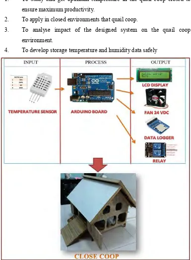
1. To study and get optimum temperature in the quail coop closed to ensure maximum productivity.
2. To apply in closed environments that quail coop.
3. To analyse impact of the designed system on the quail coop environment.
[image:16.595.140.525.224.748.2]4. To develop storage temperature and humidity data safely
4 1.4 WORK SCOPE
1. The scope of this project is related to the use of temperature control in the coop that works to get a good temperature setting for livestock.
2. The project uses five blower where warm temperatures and humidity will be reduced until the temperature stabilizes. Good for livestock, temperature is the main thing that should be considered. microcontroller will control the reaction temperature and the recorded temperature using SDCard module. 3. The project will be issued as a model because it is a project based on the
study and knowledge in reading.
5
CHAPTER 2
LITERATURE REVIEW
2.1 GENERAL OVERVIEW
6
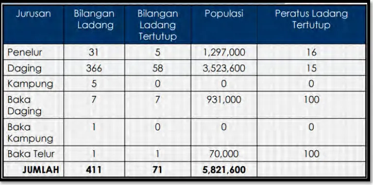
Figure 2.1 : The number of farms using closed house (Unimap portal30).
2.2 CLOSE COOP CHICKEN
7
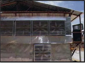
Figure 2.2 : Fan blower close coop (nu’man and profile, 2012).
Figure 2.3 : Closed coop used for poultry (afzainizam and profile, 2011) .
[image:20.595.139.492.379.521.2]8
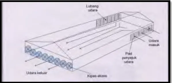
Figure 2.4 : Tunnel ventilation (Unimap portal30).
Figure 2.5 : Tunnel ventilation and humidifying air (Unimap portal30).
[image:21.595.184.483.254.399.2]9
works to remove heat from the house and reduce excess moisture. This will mngakibatkan Abatement of dust and odors and prevents the accumulation of gas accumulation ammonia and carbon dioxide in addition to a good supply of oxygen for respiration (Unimap portal30). Using temperature control technology is also closed house, chicken mortality rate can be reduced from two to three per cent compared with an opened or conventional systems (Jimat kos dengan teknologi windflex, 1997).
2.2.1 CURRENT APPLICATION
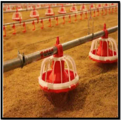
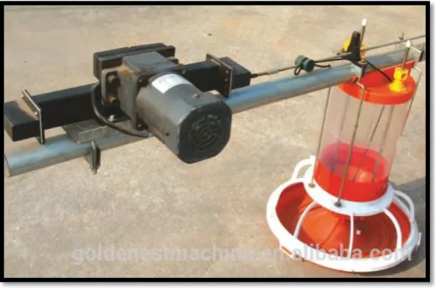
[image:22.595.218.414.546.740.2]Closed coop would use a system called temperature control for livestock which are in the house. The main components used in a closed coop is like a sealed coop and coop buildings are developed must be enclosed with the outgoing and incoming air and exhaust fans to control the ventilation system in the house where he serves as the air exchange and air out and the air in the coop. Air conditioning is also an important component of which is to ensure improved cold temperature inside the coop. Three phase supply of used and available standby generator if the power goes off. Moisture temperature sensor type used as well as the alarm system to sound an emergency alarm if there is equipment that is damaged or does not work. Automatic feeding equipment is used also to facilitate the scheduling system foragers such as pan feeder, auger feeders, feeder chain. The figure below shows the automatic feed equipment used in the livestock industry closed house.
10
Figure 2.7 : Auger feeder (Auger feeder, no date).
Figure 2.8 : Chain feeder (Alibaba, 1999).
[image:23.595.187.492.360.562.2]11
2.2.3 ADVANTAGES AND DISADVANTAGES
Malaysia has many industries that use this closed house concept. Benefits can be found by using the enclosed chicken coop is in terms of ventilation where air inside the coop can flow in and out well. This means that the temperature inside the house much lower than the temperature outside the house. Environment in the coop also give comfort to the chickens because these animals are less susceptible to interference and pressure from outside factors such as wild birds and rodents that certainly it could lead to livestock diseases and can be controlled from entering the coop. Changes obtained by using closed coop system temperature control allows the minimum and maximum temperature in a closed coop is 4 ° C (24-28 ° C) compared to 10 ° C (25> 35 ° C) for an open coop system. More chicken coop can be loaded into a closed type because of floor space for every chicken can be reduced by one third compared to the open coop. Manure from livestock can also cause persistent stench and flies breed, but with a closed coop, the stool will be dry and can easily reduce stench and flies in the environment. Closed coop can also raise chickens to excel at the same size of pens and mortality of livestock and damage is less than opened. If the pain and the death rate is less, of course, medical costs can be reduced while breeders mengungtungkan. it is more favorable to livestock farmers when market opportunities for exporting wide open and better, because of the control factor and the disease is at a minimum and guaranteed quality (afzainizam and profile, 2011).