RIT Scholar Works
Theses
4-9-2019
Bubble Interactions at Multi-Fluid Interfaces
Travis S. Emery
Follow this and additional works at:https://scholarworks.rit.edu/theses
This Dissertation is brought to you for free and open access by RIT Scholar Works. It has been accepted for inclusion in Theses by an authorized administrator of RIT Scholar Works. For more information, please [email protected].
Recommended Citation
R
.
I
.
T
Bubble Interactions at Multi-Fluid Interfaces
by
Travis S. Emery
A dissertation submitted in partial fulfillment of the requirements
for the degree of Doctorate of Philosophy in Microsystems Engineering
Microsystems Engineering Program
Kate Gleason College of Engineering
Rochester Institute of Technology
Rochester, New York
ii
Bubble Interactions at Multi-Fluid Interfaces by
Travis S. Emery
Committee Approval:
We, the undersigned committee members, certify that we have advised and/or supervised the candidate on the work described in this dissertation. We further certify that we have reviewed the dissertation manuscript and approve it in partial fulfillment of the requirements of the degree of Doctor of Philosophy in Microsystems Engineering.
______________________________________________________________________________
Dr. Satish G. Kandlikar Date
James E. Gleason Professor, Mechanical Engineering
______________________________________________________________________________
Dr. Michael Schertzer Date
Assistant Professor, Mechanical Engineering
______________________________________________________________________________
Dr. Kathleen Lamkin-Kennard Date
Associate Professor, Mechanical Engineering
______________________________________________________________________________
Dr. Anju Gupta Date
Assistant Professor, Chemical Engineering
Certified by:
______________________________________________________________________________
Dr. Bruce Smith Date
iii
Abstract
Kate Gleason College of Engineering Rochester Institute of Technology
Degree: Doctor of Philosophy Program: Microsystems Engineering
Authors Name: Travis S. Emery Advisors Name: Dr. Satish G. Kandlikar
Dissertation Title: Bubble Interactions at Multi-Fluid Interfaces
Numerous industrial applications and environmental phenomena are centered around bubble interactions at multi-fluid interfaces. These applications range from metallurgical processing to direct contact evaporation and solid shell formation. Environmental phenomena, such as bubble collisions with the sea surface microlayer and the collision of liquid encapsulated bubbles, were also considered as motivators for this work. Although the associated flow dynamics are complex, they play a vital role in governing the related application outcome, be it in terms of mass or heat transfer efficiency, bubble shell production rate, chemical reaction rate, etc. For this reason, a fundamental understanding of the fluid dynamics involved in the bubble interactions are required to aid in optimal system design. In this work, rigorous experimental work was supplemented by in-depth theoretical analysis to unravel the physics behind these bubble interactions.
iv
Acknowledgements
First and foremost, I would like to acknowledge my advisor Dr. Satish Kandlikar. From
the moment I began my work in the Thermal Analysis and Microfluidics Laboratory as an
undergraduate student, Dr. Kandlikar has guided and pushed me to understand and achieve.
He has helped further not only my technical understanding of the subject, but also my
ability to present, communicate, and lead. I would also like to thank my committee
members – Dr. Michael Schertzer, Dr. Kathleen Lamkin-Kennard, and Dr. Anju Gupta for
their continued feedback and support. I would like to thank all my fellow lab members as
well – Dr. Pruthvik Raghupathi, Dr. Arvind Jaikumar, Dr. Isaac Perez-Raya, Alyssa
Recinella, Aranya Chauhan, Jose Luis Gonzalez Hernandez, and Aniket Rishi for their
continued support and efforts to help me learn and improve. Finally, I would like to thank
all of my family and friends for always supporting and showing interest in my work. I
would most certainly not have made it to where I am today without your unconditional love
v
Contents
Abstract ... iii
Acknowledgements ... iv
Contents ...v
List of Figures ... viii
List of Tables ... xi
Nomenclature ... xii
1 Introduction ...1
1.1 The Bubble Collision Process ...1
1.2 Relevant Dimensionless Numbers ...5
1.3 Applications ...6
1.3.1 Metallurgical Relevance ...7
1.3.2 Applications of Spherical Shells ...8
1.3.3 Direct Contact Evaporation...9
1.3.4 Applications of Compound Interfaces ...11
1.4 Dissertation Structure ...12
2 Background ...14
2.1 Theory of Thin Liquid Film Hydrodynamics ...14
2.2 Bubble Passage through a Liquid-Liquid Interface...18
2.3 Bubble Growth in Direct Contact Evaporation ...24
2.4 Research Needs ...27
3 Experimental Details ...30
3.1 Bubble Passage Setup...30
3.2 Immiscible Bubble Growth Setup ...32
3.3 Interferometry Setup ...32
3.4 Liquid-Liquid and Compound Interface Collision Setup ...34
3.5 System Cleaning ...35
3.6 Video Analysis ...36
3.7 Liquid Properties ...38
4 Results and Discussion ...41
vi
4.1.1 Single Bubble Regimes ...42
4.1.2 Bubble Stream Regimes ...51
4.2 Bubble Growth in an Immiscible Liquid Droplet ...58
4.2.1 Proposed Model ...58
4.2.2 Initial Temperature Profile ...63
4.2.3 Results ...66
4.3 Dimensionless Characterization of Bubble Collisions ...74
4.3.1 Experimental Film Radius Measurement...75
4.3.2 Identification of Relevant Dimensionless Groups ...80
4.3.3 Numerical Modeling ...81
4.3.4 Prediction of Film Force Ratio and Film Radius ...86
4.4 Modeling Bubble Collisions at Liquid-Liquid and Compound Interfaces ...92
4.4.1 Liquid-Liquid Interface Collision Model...92
4.4.2 Solid-Liquid-Liquid Interface Collision Model ...99
4.4.3 Gas-Liquid-Liquid Interface Collision Model ...103
4.4.4 Experimental Validation ...107
5 Summary and Future Recommendations ...116
5.1 Key Contributions ...116
5.2 Future Recommendations ...119
6 References ...122
7 Appendix ...130
7.1 Matlab Code for Pendant Drop Analysis ...130
7.1.1 Main Controlling File ...130
7.1.2 Gaussian Bilateral Filtering Function ...132
7.2 Matlab Code for Immiscible Bubble Growth Model ...134
7.2.1 Main Controlling File ...134
7.2.2 Graphing File ...137
7.2.3 Initial Temperature Function for Constant Interface Temperature ...140
7.2.4 Initial Temperature Function for Variable Interface Temperature ...141
7.3 Matlab Code for Bubble Collision Models ...142
7.3.1 Main Controlling File ...143
vii
7.3.3 Solid-Liquid Collision Function ...152
7.3.4 Gas-Liquid Collision Function ...154
7.3.5 Liquid-Liquid Collision Function ...157
7.3.6 Solid-Liquid-Liquid Collision Function ...160
7.3.7 Gas-Liquid-Liquid Collision Function ...164
7.3.8 Drag Coefficient Function ...169
7.3.9 Derivative Function ...169
viii
List of Figures
Figure 1. (a) Bubble rise and (b) impact with a liquid-liquid interface with (c)-(f)
possible collision outcomes. ... 2
Figure 2. Formation of thin liquid films in various scenarios. Redrawn from [11]. ... 3
Figure 3. Bubble collision at two types of compound interfaces: (a) solid-liquid-liquid, and (b) gas-liquid-liquid. ... 5
Figure 4. Bubble passage through molten metal and slag commonly seen in metallurgy
[16]. ... 8
Figure 5. Apparatus used by Kawano et al. [22] for production of solid spherical shells. 9
Figure 6. Schematic of typical spray column evaporator. Redrawn from [38]. ... 10
Figure 7. Schematic of bubble bursting at a compound interface to generate functional nanoemulsions [44]. ... 12
Figure 8. Schematic of bubble or drop collision [47]. ... 14
Figure 9. Bubble resting at a deformable interface. Redrawn from [60]. ... 17
Figure 10. Bubble shell formation during passage of a bubble through an ink-water and
kerosene interface [35]. ... 19
Figure 11. (a) Ripples and microdroplets formed during film rupture and (b)-(f) stages of film rupture during bubble passage through an interface [69]. ... 21
Figure 12. (a) Dimensionless mapping of bubble passage through a liquid-liquid
interface, (b) experimental and (c) computational results for bubble passage through a liquid-liquid interface with Bo=13.3 and Ar=4.15 [18]. ... 23
Figure 13. Possible configurations of liquid-gas two phase bubbles. Redrawn from [71].
... 25
Figure 14. Comparison of instantaneous heat transfer coefficients using various models. ... 26
Figure 15. (a) Schematic of experimental setup used for bubble passage through a liquid-liquid interface, and (b) expanded view of needle holder. ... 31
Figure 16. Experimental setup used to measure bubble growth in an immiscible droplet.
... 32
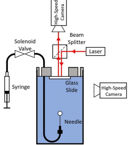
Figure 17. Schematic of experimental setup used to capture bubble collisions with a solid surface. ... 33
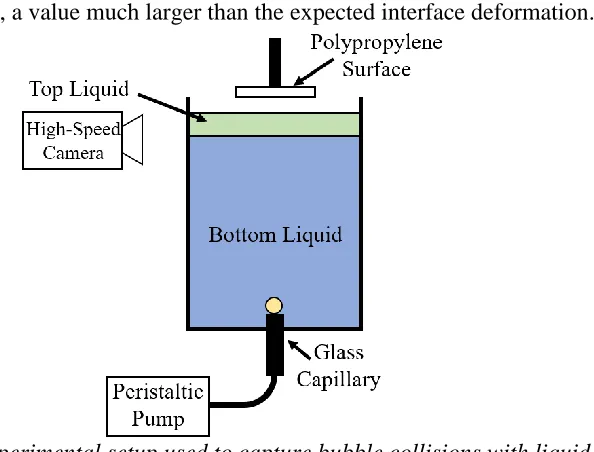
Figure 18. Experimental setup used to capture bubble collisions with liquid-liquid and compound interfaces. ... 35
Figure 19. (a) 4 mm outer diameter capillary used for spatial calibration, (b) horizontal and vertical bubble diameter measurement, (b)-(c) bubble displacement used in velocity calculation. ... 37
Figure 20. (a) Experimental setup and (b)-(f) pendant drop image processing used to determine interfacial tension. ... 39
Figure 21. Flow patterns seen with single bubble passage through a liquid-liquid
interface... 42
Figure 22. Trapped 3.3 mm diameter bubble seen with water (bottom) and silicone oil
ix
Figure 23. Bubble shell formation shown schematically and experimentally with water
(bottom) and silicone oil 100 (top). ... 45
Figure 24. Long tail formation for 2.3 mm diameter bubble passing through silicone oil 100 (bottom) – ethanol (top) interface. ... 46
Figure 25. Shell rupture as seen in experiments and a schematic illustration of the rupture process... 47
Figure 26. Dimensionless plot for single bubble passage through a liquid-liquid interface. ... 50
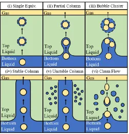
Figure 27. Flow regimes seen with bubbles streams passing through a liquid-liquid interface... 51
Figure 28. (a)-(d) Partial column formation seen with water and silicone oil 20, (e)-(h) bubble cluster formation without coalescence seen with water and silicone oil 10, and (i)-(l) bubble cluster formation with coalescence seen with PP1 and water. ... 53
Figure 29. Formation of a stable bubble column shown (a)-(d) schematically and (g)-(j) experimentally with water and silicone oil 10, unstable column formation shown (e) schematically and (k) as seen with silicone oil 20 and ethanol, and churn flow shown (f) schematically and (l) as seen with PP1 and water. ... 54
Figure 30. Dimensionless flow map for bubble stream passage through a liquid-liquid interface... 57
Figure 31. Concentric model for bubble growth in an immiscible droplet. ... 59
Figure 32. Coordinate transformation to immobilize boundary conditions. ... 61
Figure 33. Temperature profile in dimensional and dimensionless coordinate systems for (a)-(b) variable liquid-liquid interface temperature and (c)-(d) constant liquid-liquid interface temperature. ... 65
Figure 34. Comparison of (a) ζ effect and (b) γ effect on bubble growth using the current model and previous described by Avedisian and Suresh [79]. ... 66
Figure 35. Impact of 𝑇̅𝑠 on (a) dimensionless initial temperature profile, and (b) dimensionless bubble growth. ... 67
Figure 36. (a) High speed visualization of bubble growth within an FC-72 droplet at a superheat of 34°C and experimental versus predicted bubble growth for (b) current experiments and (c and d) experiments found in literature... 69
Figure 37. Effect of liquid superheat on bubble growth. ... 70
Figure 38. Influence of initial shell thickness on dimensionless bubble growth. ... 71
Figure 39. Influence of ζ on immiscible bubble growth. ... 72
Figure 40. Influence of γ on bubble growth when the liquid-liquid interface during initial heating is (a) constant and (b) variable. ... 73
Figure 41. Schematic of a bubble collision with a solid surface. ... 74
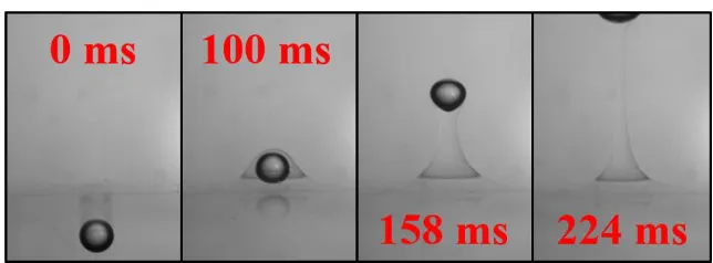
Figure 42. Sequence of images showing the collision of a bubble with a glass surface. Initial distance between the needle tip and surface is 4.1 mm. ... 76
Figure 43. Variation in bubble trajectory with change in distance between needle tip and glass surface, L. ... 77
x
Figure 45. Evolution of film rupture and three-phase contact formation. ... 79
Figure 46. Interference patterns in subsequent collisions of a bubble with a glass surface where L=4.1mm. Scale bar is 0.25mm. ... 79
Figure 47. Predicted drag coefficient values for various Reynolds and Weber number
bubbles in water. ... 84
Figure 48. Force evolution of a 0.74 mm bubble collision with a water/air interface. .... 87
Figure 49. Dimensionless plot of film force ratio for bubbles with varying Bo and Ar impacting (a) a solid surface at terminal and (b) nonterminal velocities, and (c) a free surface at terminal and (d) nonterminal velocities. ... 88
Figure 50. Dimensionless film radius for bubbles with varying Bo and Ar impacting (a) a
solid surface at terminal and (b) nonterminal velocities, and (c) a free surface at terminal and (d) nonterminal velocities. ... 90
Figure 51. Comparison between experimental and predicted film radius for bubbles
colliding with a solid surface. ... 91
Figure 52. Schematic of proposed model for bubble collisions at a liquid-liquid interface. ... 93
Figure 53. Schematic of proposed model for bubble collisions at a solid-liquid-liquid interface... 99
Figure 54. Schematic of the proposed model for bubble collisions at a gas-liquid-liquid interface... 103
Figure 55. Comparison of numerical model for bubble collisions at a liquid-liquid interface to experimental data for (a) bubbles impacting various water-silicone oil interfaces at terminal velocity, (b) bubbles impact a water-10 cSt silicone oil interface at nonterminal velocities, and (c) bubble of various sizes impacting a PP11-water interface from Vakarelski et al. [117]. ... 108
Figure 56. Numerical predictions of (a) film thickness and (b) film pressure buildup during the first collision of a 0.65 mm radius bubble at terminal velocity colliding with a water-5 cSt silicone oil interface... 110
Figure 57. Comparison of numerical model for bubble collisions at a solid-liquid-liquid interface to experimental data for bubbles colliding with various polypropylene-silicone oil-water interfaces at terminal velocity. ... 111
Figure 58. Bubble surface and liquid-liquid interface location at the central axis for various initial film thicknesses... 112
Figure 59. Thickness and pressure distributions in the (a)-(b) upper, and (c)-(d) lower films during a bubble collision at a solid-5 cSt silicone oil-water interface. ... 113
Figure 60. Comparison of numerical model for bubble collisions at a gas-liquid-liquid interface to experimental data for bubbles colliding with various air-silicone oil-water interfaces at terminal velocity. ... 114
xi
List of Tables
Table 1. Relevant dimensionless numbers and their associated meaning. ... 6
Table 2. Properties of experimental liquids at 25°C. ... 38
Table 3. Experimental liquid combinations and properties... 40
Table 4. Liquid properties used in immiscible bubble growth model. ... 70
xii
Nomenclature
Symbol Description Units/Value
FB Buoyancy force N
FD Drag force N
FH History or Basset force N
FA Added mass force N
FF Film force N
Bo Bond number -
Mo Morton number -
We Weber number -
Ca Capillary number -
Oh Ohnesorge number -
La Laplace number -
Ar Archimedes number -
Re Reynolds number -
Fr Froude number -
D Bubble or droplet diameter – subscript h or v for horizontal or vertical
m
R Bubble or droplet radius m
V Velocity m/s
g Gravitational acceleration m/s2
h Film thickness – subscript for associated layer m
p Pressure – subscript for associated layer Pa
xiii
z Axial direction m
t Time s
Vr Radial velocity m/s
Vz Axial velocity m/s
p0 Nominal bulk pressure Pa
RF Film radius m
Δp Excess film pressure Pa
Vg* Bubble volume required for passage m3
z* Dimensionless bubble displacement -
h* Dimensionless film thickness -
t* Dimensionless time -
Si Spreading coefficient – subscript A, B, G for dispersed,
continuous, or gas phase respectively
N/m
Nu Nusselt number -
Pe Peclet number -
Ja Jakob number -
VT Terminal velocity m/s
CD Drag coefficient -
y Vertical bubble position m
Δt Time between frames s
SO Silicone oil -
a Drop apex radius of curvature m
x* Dimensionless drop profile x coordinate -
xiv
Cm Added mass coefficient -
KE Kinetic energy J
SE Excess surface energy J
RF* Dimensionless film radius -
Δp* Dimensionless excess film pressure -
Vs Superficial velocity m/s
f Frequency s-1
Fr* Modified Froude number -
S Top liquid height m
R1 Liquid-vapor interface location m
R2 Liquid-liquid interface location m
k Thermal conductivity – subscript denotes associated liquid
W/m·K
Tsat Saturation temperature °C
v radial velocity m/s
T Liquid temperature – subscript denotes associated liquid °C
hfg Latent heat of vaporization J/kg
Cp,1 Specific heat of volatile liquid J/kg·K
𝑅̅1 Dimensionless liquid-vapor interface location -
𝑅̅2 Dimensionless liquid-liquid interface location -
𝑟̅ Dimensionless radial coordinate -
𝑇̅ Dimensionless liquid temperature – subscript denotes associated liquid
-
R1,0 Initial vapor core radius m
xv
𝑅̅1,0 Dimensionless initial vapor core radius -
𝑅̅2,0 Dimensionless initial drop radius -
T0 Initial subcooled temperature °C
TS Required superheat for bubble nucleation °C
T∞ Bulk liquid temperature °C
𝑇̅𝑠 Dimensionless superheat required for bubble nucleation -
ΔT Liquid superheat °C
ℎ0
̅̅̅ Dimensionless initial shell thickness -
L Distance between needle or capillary and interface m
∆𝐶𝐷∗ Normalized drag coefficient -
zS Free surface deformation m
rm Outer radial boundary m
Vimp Impact velocity m/s
zI Liquid-liquid interface deformation m
zb Bubble surface deformation m
h00 Initial distance between top of bubble and interface m
FI Interface force N
H1 Top film thickness at axis of symmetry m
H2 Bottom film thickness at axis of symmetry m
h1,0 Initial top film thickness m
h2,00 Initial distance between top of bubble and interface m
xvi
Greek Letters
ρ Density – subscript denotes associated liquid or vapor kg/m3
μ Viscosity – subscript denotes associated liquid Pa·s
σ Surface tension – subscript denotes associated liquid N/m
σI Interfacial tension N/m
Π Disjoining pressure Pa
θ Opening angle °
φ Tangent angle to drop profile °
ω Shape factor -
Γ Normalized density difference -
α Thermal diffusivity – subscript denotes associated liquid m2/s
ε Normalized vapor density ratio, ε=1-ρv/ ρ1 -
η Dimensionless bubble growth coordinate -
τ Dimensionless time -
γ Thermal diffusivity ratio -
ζ Thermal conductivity ratio -
ψ Normalized distance between bubble and solid surface -
χ Bubble aspect ratio -
τv,T Normal viscous stress Pa
𝜎̅ 1/𝜎̅ = (1/𝜎𝐼+ 1/𝜎𝐵) N/m
𝜆𝐼 𝜆𝐼 = √𝜎𝐼/∆𝜌𝑔 m
𝜆𝑇 𝜆𝑇 = √𝜎𝑇/𝜌𝑇𝑔 m
γE Euler constant -
1
Chapter 1
1
Introduction
The motion of bubbles in a liquid medium has captured the attention of scientists and
researchers for centuries. Leonardo da Vinci was perhaps the first to scientifically
investigate and report on the failure of large bubbles to follow a rectilinear rise path; this
finding was later dubbed Leonardo’s paradox [1]. It wasn’t until several centuries after his
death that the mystery was solved, and the phenomenon was determined to be a result of
wake instabilities. In the early 19th century, Thomas Young introduced the concept of surface tension in his qualitative studies on the shape of fluid-fluid interfaces under
capillary forces [2]. A year later, Pierre-Simon Laplace gave Young’s qualitative theory a
mathematical description, and the well-known Young-Laplace equation was derived [3].
Later that same century, Osborne Reynolds analyzed fluid flow in thin films, which
resulted in the lubrication equations that are still used extensively today [4]. In more recent
years, technological advances have allowed us to explore many of the underlying physics
associated with bubble motion and bubble interactions with other surfaces in a liquid
medium. Despite the centuries worth of research, many complexities associated with
bubble interactions still remain a mystery. The focus of this dissertation is to broach these
topics and develop an improved understanding of bubble interactions at multi-fluid
interfaces.
1.1 The Bubble Collision Process
A brief overview of a bubble’s collision with a liquid-liquid interface is presented in
this section. Consider first, two immiscible liquids of different densities in stratified layers
with the heavier liquid being the bottom layer as shown in Figure 1(a). When a bubble is
2
and the surrounding liquid induces a constant buoyancy force (FB) causing it to rise. The
bubble will accelerate upwards until the growing drag force (FD) balances out the buoyancy
force. During its acceleration, the drag force requires some time to establish itself; this
results in a history force (FH), also known as the Basset force [5]. This history force can be
neglected when the bubble surface is considered mobile but must be taken into account for
immobile bubble surface conditions [6]. Additionally, when the bubble undergoes any sort
of acceleration, the surrounding liquid must also accelerate with it, giving rise to an added
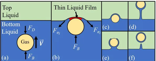
mass force (FA). Eventually, the bubble will impact the horizontal interface between the
liquid layers. When the bubble collides with the interface, interfacial tension resists the
bubble motion and a thin liquid film is formed between the bubble and the interface, as
shown in Figure 1(b). The pressure in this film increases during the impact and imparts a
film force (FF) onto the bubble. If the film is very thin, surface forces due to van der Waals
and electrical double layer interactions also become important. Typically, a film thickness
of ~100 nm or less is required before these surface forces need to be taken into account [7].
For bubble collisions with very low Reynolds numbers (Re≪1), such film thicknesses are
routinely achieved during the collisions, and these forces take on an important role in the
film thinning process [8]. However, during dynamic (Re≫1) bubble collisions, the film
[image:19.612.176.473.71.187.2]thickness is on the order of micrometers, and therefore, these surface forces can be
3
neglected [9]. At this point in the collision process, there are a number of different
variations. The bubble may become trapped at the interface, Figure 1(c), or pass through
the interface with some volume of the bottom liquid entrained around and/or behind the
bubble, Figure 1(d)-(f). A similar process is seen in bubble-free surface collisions in which
the outcome is determined based on two competing processes: (i) the thinning of the liquid
between the bubble and interface, and (ii) the expense of the kinetic energy to increase the
free energy of the system via an increase in bubble surface area due to deformation [10].
For bubble passage through a liquid-liquid interface, more significant degrees of interface
deformation are commonly seen; thus, the kinetic to free surface energy transfer would also
stem from increased interfacial area between the liquids. The thinning rate of the liquid
column entrained behind the bubble also plays a significant role in determining the
outcome.
Thin film formation is also seen with bubble and droplet collisions with a free surface,
a solid surface, or another bubble or droplet, as well as solid particle collisions with a
liquid-liquid interface or free surface. Some of these scenarios are shown in Figure 2 [11].
In any of these cases, the hydrodynamics of the liquid film play a dominant role in dictating
the collision process. Lubrication theory is customarily used to define the thinning rate of
4
the film regardless of its formation method. As such, a significant amount of research has
focused on details of the thinning process. A more in-depth review of the related theory is
discussed in Section 2.1.
The interaction of a stream of bubbles with a liquid-liquid interface adds significant
complexity to the process compared to single bubble interactions. In addition to liquid
properties, bubble size, and bubble velocity, the frequency with which the bubbles impact
the interface becomes a significant parameter. As will be discussed in Section 4.1.2, the
variation in possible outcomes for bubble streams also increases. The general outline of the
collision process begins in a manner similar to single bubble passage with a continuous
stream of bubbles rising through the bottom liquid. In this scenario, however, the collision
outcome of each bubble will be dependent on the collision outcome of the preceding
bubble(s). At very low frequency, the preceding bubble may have already passed through
the interface, and the process would be the same as single bubble passage. At intermediate
frequencies, multiple bubbles may reach the interface simultaneously and pass through as
a group. At yet higher frequencies, columns of the bottom liquid may begin to be formed.
In these scenarios, multiple thin liquid films may exist between the bubbles and the
interface as well as between the bubbles themselves if they are in contact. This
configuration has received significantly less research focus compared to single bubble
passage, and as a result, the exact criteria for the formation of these flow patterns has not
been previously explored.
A new focus area recently introduced to this field encompasses bubble collisions at
so-called “compound interfaces”. A compound interface is classified here by the presence of
5
may be a solid surface or a free surface, as shown in Figure 3(a) and (b). These compound
interfaces will be referred to as solid-liquid-liquid and gas-liquid-liquid interfaces
throughout the dissertation. The forces acting on the bubble during its collision with a
compound interface would remain the same as compared to a liquid-liquid interface
collision. In such a system, two thin liquid films would be formed during the collision: one
made up of the bulk liquid and the other made up of the secondary liquid. These systems
have received very little research exposure but have wide spread implications, as discussed
in Section 1.3.4.
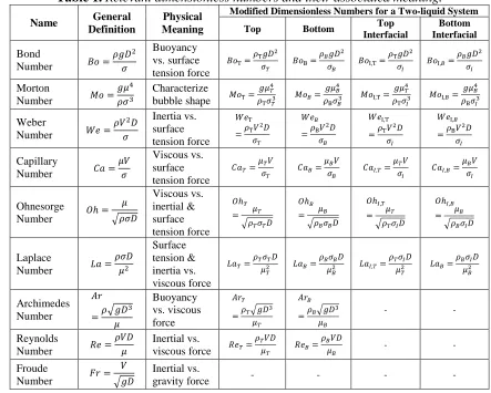
1.2 Relevant Dimensionless Numbers
Dimensionless numbers provide a powerful tool in elucidating the dominant underlying
mechanisms in complex processes. The prominent forces during bubble collisions with a
liquid-liquid interface include buoyancy, viscous forces, surface tension, and inertia.
Comparing the relative magnitude of these forces leads to several dimensionless numbers,
which are shown in Table 1 along with other relevant dimensionless numbers commonly
used in fluid mechanics. Since the system currently being studied involves two liquids, the
dimensionless numbers must specify which liquid properties are being used. These are
herein defined as the “bottom” or “top” dimensionless numbers with bottom referring to
the properties of the denser liquid and top referring to the properties of the less dense liquid.
Figure 3. Bubble collision at two types of compound interfaces: (a)
6
Additionally, the interfacial tension, a crucial parameter required to define the system,
needs to be included in these dimensionless numbers. To this extent, “interfacial”
dimensionless numbers are defined as those using interfacial tension instead of the
associated liquid surface tension. For example, the “bottom Bond number” would employ
the bottom liquid density and surface tension, while the “bottom interfacial Bond number”
would utilize the bottom liquid density and interfacial tension. All quantities in Table 1 are
[image:23.612.99.542.275.630.2]defined in this manner.
Table 1.Relevant dimensionless numbers and their associated meaning.
Name General
Definition
Physical Meaning
Modified Dimensionless Numbers for a Two-liquid System
Top Bottom Top
Interfacial
Bottom Interfacial
Bond
Number 𝐵𝑜 = 𝜌𝑔𝐷2
𝜎
Buoyancy vs. surface tension force
𝐵𝑜T=
𝜌T𝑔𝐷2
𝜎𝑇
𝐵𝑜B=
𝜌𝐵𝑔𝐷2
𝜎𝐵
𝐵𝑜I,T=
𝜌T𝑔𝐷2
𝜎𝐼
𝐵𝑜I,𝐵=
𝜌𝐵𝑔𝐷2
𝜎𝐼
Morton
Number 𝑀𝑜 = 𝑔𝜇4
𝜌𝜎3
Characterize
bubble shape 𝑀𝑜T= 𝑔𝜇𝑇4
𝜌T𝜎𝑇3
𝑀𝑜𝐵=
𝑔𝜇𝐵4
𝜌B𝜎𝐵3
𝑀𝑜I,T=
𝑔𝜇𝑇4
𝜌T𝜎𝐼3
𝑀𝑜I,𝐵=
𝑔𝜇𝐵4
𝜌B𝜎𝐼3
Weber
Number 𝑊𝑒 = 𝜌𝑉2𝐷
𝜎
Inertia vs. surface tension force
𝑊𝑒T
=𝜌T𝑉
2𝐷
𝜎𝑇
𝑊𝑒𝐵
=𝜌B𝑉
2𝐷
𝜎𝐵
𝑊𝑒I,T
=𝜌T𝑉
2𝐷
𝜎𝐼
𝑊𝑒I,𝐵
=𝜌B𝑉
2𝐷
𝜎𝐼
Capillary
Number 𝐶𝑎 = 𝜇𝑉
𝜎
Viscous vs. surface tension force
𝐶𝑎𝑇=
𝜇𝑇𝑉
𝜎𝑇
𝐶𝑎𝐵=
𝜇𝐵𝑉
𝜎𝐵
𝐶𝑎𝐼,𝑇=
𝜇𝑇𝑉
𝜎𝐼
𝐶𝑎𝐼,𝐵=
𝜇𝐵𝑉
𝜎𝐼
Ohnesorge
Number 𝑂ℎ = 𝜇 √𝜌𝜎𝐷 Viscous vs. inertial & surface tension force 𝑂ℎ𝑇
= 𝜇𝑇 √𝜌𝑇𝜎𝑇𝐷
𝑂ℎ𝐵
= 𝜇𝐵 √𝜌𝐵𝜎𝐵𝐷
𝑂ℎ𝐼,𝑇
= 𝜇𝑇 √𝜌𝑇𝜎𝐼𝐷
𝑂ℎ𝐼,𝐵
= 𝜇𝐵 √𝜌𝐵𝜎𝐼𝐷
Laplace
Number 𝐿𝑎 = 𝜌𝜎𝐷 𝜇2 Surface tension & inertia vs. viscous force
𝐿𝑎𝑇=
𝜌𝑇𝜎𝑇𝐷
𝜇𝑇2
𝐿𝑎𝐵=
𝜌𝐵𝜎𝐵𝐷
𝜇𝐵2
𝐿𝑎𝐼,𝑇=
𝜌𝑇𝜎𝐼𝐷
𝜇𝑇2
𝐿𝑎𝐵=
𝜌𝐵𝜎𝐼𝐷
𝜇𝐵2
Archimedes Number 𝐴𝑟 =𝜌√𝑔𝐷 3 𝜇 Buoyancy vs. viscous force 𝐴𝑟𝑇
=𝜌𝑇√𝑔𝐷
3
𝜇𝑇
𝐴𝑟𝐵
=𝜌𝐵√𝑔𝐷
3
𝜇𝐵
- -
Reynolds
Number 𝑅𝑒 = 𝜌𝑉𝐷
𝜇
Inertial vs.
viscous force 𝑅𝑒𝑇= 𝜌𝑇𝑉𝐷
𝜇𝑇
𝑅𝑒𝐵=
𝜌𝐵𝑉𝐷
𝜇𝐵
- -
Froude
Number 𝐹𝑟 = 𝑉 √𝑔𝐷
Inertial vs.
gravity force - - - -
1.3 Applications
Bubble interactions with a liquid-liquid interface have been studied due to their
7
evaporation [17], nuclear reactor safety [18], and liquid-liquid extraction [19,20], as well
as environmental phenomena such as the ascent of plumes through the Earth’s mantle [21].
In such applications, mass or heat transfer between stratified liquid layers is often the
primary goal. In order to improve the efficiency of the mass or heat transfer processes
across the interface, it is desirable to increase the effective contact area between the liquids.
A relatively simple method commonly employed is the bubbling of gas through the
stratified liquid layers. Another application of bubble passage through a liquid-liquid
interface is for the production of spherical shells [22], as discussed in further detail in
Section 1.3.2. In any of these applications, the outcome of the bubble collision dictates the
efficiency of the process. Compound interfaces are reminiscent of numerous systems found
in nature, as well as double emulsion collisions, as outlined in Section 1.3.4. There are a
number of parameters that can affect these systems, including the properties of the two
liquids, specifically the densities, viscosities, and surface tensions, as well as the bubble
size, shape, and impact velocity.
1.3.1 Metallurgical Relevance
A significant amount of previous work on bubble passage through a liquid-liquid
interface has been performed in association with its relevance to metallurgical processing
such as secondary refining, copper conversion, and gas stirred ladling [12–16,23–29]. In
such processes, molten metal and molten slag form two stratified liquid layers. A chemical
reaction takes place at the interface to induce various results such as decarburization,
dephosphorization, and desiliconization [16]. Mixing of the two liquids is required to
increase the efficiency of the chemical process. Due to the high temperatures, this is
8
metal across the interface increases the effective contact surface area over which the
chemical reaction may occur [29]. Therefore, the behavior of the gas bubbles as they pass
through the liquid-liquid interface is directly associated with the overall reaction rate [16].
1.3.2 Applications of Spherical Shells
One possible outcome of a bubble collision with a liquid-liquid interface is the
formation of a shell of the lower liquid around the bubble as it leaves the interface [22,30–
35]. Solidification of this shell as it continues to rise through the top liquid enables the
production of spherical metallic shells that can contain various gases. Kawano et al. [22]
have demonstrated the feasibility of generating these shell using the system shown in
Figure 5. As described by Lee et al. [36], the applications of these bubble shells is
widespread. Aluminum shells would burn more smoothly than flakes or powders when
utilized in an oxidizer as a high-performance solid fuel. Metallic shells filled with a paraffin
which melts near body temperature could be used as insulation in space garments for
extravehicular activity. Other potential uses include shock-absorbing armor plates,
pharmaceuticals, catalytic reagents, and fire retardants. Although these shells have
[image:25.612.255.398.157.328.2]previously been made using annular nozzles, the apparatus required for solidification of
Figure 4. Bubble passage through molten metal and slag commonly seen in
9
the shells is very large [22]. Instead, the use of a simple system in which the shells are
formed via bubble passage through a liquid-liquid interface could simplify this production
process.
1.3.3 Direct Contact Evaporation
A specific motivation behind the present work is the application of the bubble collision
process to direct contact evaporation. In surface type heat exchangers, such as the
commonly used shell and tube type, heat is transferred through a metallic barrier present
between two liquids. The mere presence of this barrier introduces a number of issues. The
solid barrier lowers the heat transfer rate, and is exposed to fouling, corrosion, and thermal
stresses [37]. Some of these issues may be overcome with the use of specialized materials
or additives, but their use further raises the material costs associated with these heat
exchangers. The operational cost for these systems is high due to continuous maintenance
and the associated fouling and corrosion as well [37]. Direct contact heat exchangers
eliminate the need for a metallic barrier by bringing the two liquid streams into direct
physical contact. This increases the associated heat transfer coefficients and reduces
material and operational costs [37]. However, the system does require the two liquids to be
at the same pressure, and they must be immiscible [37]. These systems have broad
Figure 5.Apparatus used by Kawano et al. [22] for production of solid spherical
10
industrial applications such as water desalination, solar energy applications, and power
production from low-grade energy resources, such as geothermal energy. While each of
these applications hold substantial worth of their own, their combined importance further
motivates research efforts in the field of direct contact evaporation.
A setup commonly employed for direct contact heat transfer is the spray column
evaporator. In these systems, droplets of a volatile lighter liquid are typically injected into
the bottom of a container while a heavier bulk liquid is introduced from the top to create a
counter-current spray column, such as that shown in Figure 6 [38]. Evaporation of the
droplets results in a net cooling effect on the bulk liquid. To induce evaporation of the
volatile liquid droplets, the bulk liquid must be at a temperature above the saturation
temperature of the volatile liquid. The excess temperature above the saturation temperature
is commonly referred to as the superheat [38]. In pure liquid, the degree of superheat
required to induce nucleation can be significant [39]. A number of analytical and
[image:27.612.234.456.464.694.2]experimental studies have been carried out investigating various aspects of these systems,
11
such as the influence of initial droplet size, liquid flow rates, and column height [38,40,41].
Some theoretical models for bubble growth have also been proposed, as discussed in
Section 2.3.
Although current direct contact evaporators typically inject droplets of a volatile liquid
into an immiscible bulk liquid [31,42], the use of pre-nucleated droplets have been
hypothesized to further improve the heat transfer performance. The present work on bubble
passage through a liquid-liquid interface presents one method of producing such
pre-nucleated droplets, as shown in Figure 1(f). Since the vapor core would already be
established, the degree of superheat required to induce boiling would be very small, thus
improving the efficiency of the direct contact evaporation systems. However, due in part
to the relatively limited understanding currently available for the formation of these bubble
shells via bubble passage through a liquid-liquid interface, this method has not yet been
implemented for this purpose.
1.3.4 Applications of Compound Interfaces
Recently, bubble bursting at an air/oil/water-with-surfactant compound interface was
utilized as a means of dispersing sub-micrometer oil droplets into the water to create
nanoemulsions, as shown in Figure 7 [43,44]. These functional nanoemulsions are of
interest to a number of different applications such as drug delivery, material science,
functional foods, and nutraceuticals. This simple technique offers a low-cost and
energy-efficient platform to produce nanoemulsions that was not previously available.
Furthermore, this technique is scalable and has the ability to produce nanoemulsions in
large volumes. Another interest area related to compound interfaces is the sea surface
12
lipids, proteins, and hydrocarbons [45]. Therefore, when a bubble collides with the ocean
surface, it actually interacts with a compound interface made up of the ocean water and
this microlayer. Lastly, the collision of liquid-encapsulated bubbles (the same as those
previously mentioned for spherical shell production and direct contact evaporation) with
other bubbles or interfaces is considered. Most bubbles formed in nature are, in fact, coated
with an organic oil layer roughly 1-100 μm thick [46]. When these encapsulated bubbles
collide, a compound interface is formed which will significantly alter the film drainage
dynamics as compared to the collision of bare bubbles.
1.4 Dissertation Structure
The dissertation is structured as follows:
Chapter 1: Introduction – An overview of the bubble collision process is given along with
the dimensionless numbers used to describe such systems and relevant applications.
Chapter 2: Background – In this section, relevant literature related to bubble collisions and
direct contact heat transfer is reviewed. This includes thin liquid film hydrodynamics,
bubble passage through a liquid-liquid interface, and immiscible bubble growth.
Figure 7. Schematic of bubble bursting at a compound interface to generate
13
Chapter 3: Approach – Details of the experimental setup are described here. The procedure
during testing as well as the analysis is also presented.
Chapter 4: Results and Discussion – The results are divided into four main section: (i) flow
regimes and transition criteria during bubble passage through a liquid-liquid interface, (ii)
bubble growth in an immiscible liquid droplet, (iii) dimensionless characterization of
bubble collisions, and (iv) modeling bubble collisions at liquid-liquid and compound
interfaces.
Chapter 5: Summary and Future Recommendation – This section highlights the key
contributions made by this work. Recommendations for extensions of this work in the
future are also presented.
Chapter 6: References – Sources used throughout the dissertation are listed.
Chapter 7: Appendix – Additional information regarding Matlab code written for the
14
Chapter 2
2
Background
2.1 Theory of Thin Liquid Film Hydrodynamics
The drainage and thinning of the liquid film formed between a bubble and an interface
during collision plays a crucial role in dictating the collision process. A significant focal
point of previous research has concentrated on deriving theory to describe important
characteristics of the film, such as the thinning rate, radial film size, and critical rupture
thickness. The most general case may be thought of as two fluid drops colliding under an
applied external force in a surrounding liquid medium as shown in Figure 8 [47]. It is
typically assumed that the film is axisymmetric about the vertical axis of the bubble and
the pressure in the film does not vary across its thickness. This enables the film thickness
and pressure to be written as functions of only radial location, r, and time, t. The augmented
Young-Laplace equation is used to define the pressure buildup within the film, while the
Stokes-Reynolds equation, defined from lubrication theory, is applied to describe the
thinning rate. The specific solution to this set of equations will vary depending on the
boundary conditions applied. The theory is applicable to both bubble and droplet collisions.
The augmented Young-Laplace equation may be derived either through a balance of
normal forces against surface tension forces on a surface element of a bubble, or by
15
minimizing the Helmholtz surface free energy of the system [47,48]. Although the lengthy
derivation is not included in full, the linearized equation for the general case of two bubbles
colliding is given as:
1 2 𝜎̅ 𝑟 𝜕 𝜕𝑟(𝑟 𝜕ℎ 𝜕𝑟) =
2𝜎̅
𝑅̅ − 𝛱 − 𝑝 (1)
where 1 𝑅̅ =
1 2(
1 𝑅1+
1
𝑅2) and 1 𝜎̅=
1 2(
1 𝜎1+
1 𝜎2)
where σ is the surface tension, R is the bubble radius with subscripts 1 or 2 corresponding
to the respective bubble (see Figure 8), h is the film thickness, Π is the disjoining pressure,
and p is the hydrodynamic pressure in the film. The disjoining pressure is defined using
DLVO theory, developed by Derjaguin and Landau [49], and Verwey and Overbeek [50],
which incorporates the effects of van der Waals forces and electrostatic double layer
interactions. These forces only become relevant when the film has reached very small
thicknesses, ~100 nm, which are much thinner than those typically seen in dynamic bubble
collisions, ~5 μm, until just before film rupture [7,9,51–53]. As such, they will not be a
focal point of the present background review.
It is typically assumed that since the film thickness is much less than the radial size of
the film, the application of Reynolds lubrication theory is appropriate [4]. Through
dimensional analysis, it can be shown that the pressure variation across the film thickness
is negligibly small, and the radial velocity is dominant. With the previous axisymmetric
assumption, the Stokes equation describing the radial film flow may be written as:
𝜕𝑝 𝜕𝑟 = 𝜇
𝜕2𝑉𝑟
𝜕𝑧2 (2)
where μ is the viscosity of the liquid in the film, and Vr is the radial velocity. The continuity
16 1
𝑟 𝜕
𝜕𝑟(𝑟𝑉𝑟) + 𝜕𝑉𝑧
𝜕𝑧 = 0 (3)
where Vz is the axial velocity. Equation 2 may be integrated twice with respect to z and the
appropriate boundary conditions must be applied to obtain the radial velocity profile.
Substituting this profile into the continuity equation and integrating from z=0 to h yields
the film thinning rate. If tangentially immobile interfaces are assumed, the thinning rate
may be written as:
𝜕ℎ 𝜕𝑡 =
1 12𝜇𝑟
𝜕 𝜕𝑟(𝑟ℎ
3𝜕𝑝
𝜕𝑟) (4)
If one of the surface is instead assumed to have a zero shear stress condition, the 12 in the
denominator of should be replaced with a 3. This equation, along with the Young-Laplace
equation, gives a complete description of the spatial and temporal evolution of the thin
liquid film.
A number of flat film models, which assume film thickness to be only a function of
time, have also been derived to reach a simple closed form solution for the film thinning
rate. Much of these stem from the work of Reynolds [4], who considered the approach of
two flat parallel plates. Scheludko [54] was the first to apply this to the thinning of
microscopic circular films. Equation 4 is integrated twice in the radial dimension to yield
a function for the pressure. Assuming immobile surfaces, this is given as:
𝑝 = 𝑝0−
3𝜇𝑟2 ℎ3
𝑑ℎ
𝑑𝑡 (5)
where p0 is the pressure at the film’s rim. The film force is then equated to the force
pressing the surfaces of the film together:
𝜋𝑅𝐹2∆𝑝 = ∫ 2𝜋𝑟(𝑝 − 𝑝0)𝑑𝑟
𝑅𝐹
0
= −3𝜋𝜇𝑅𝐹
4
2ℎ3
𝑑ℎ
17
where RF is the radial film size, and Δp=2σ/R-Π is the excess pressure in the film. The final
thinning rate equation is thus given as:
−𝑑ℎ 𝑑𝑡 =
2ℎ3∆𝑝
3𝜇𝑅𝐹2 (7)
While this does present a simple closed form solution, the model makes several restricting
assumptions: (i) viscosity in the film is equal to that in the bulk, (ii) negligible evaporation,
(iii) flow between parallel flat surfaces, and (iv) tangentially immobile surfaces [52]. A
number of increasingly complex theoretical extensions have been made to include the
effect of thickness non-homogeneities and the tangential mobility of the surfaces [52,55–
57]. However, it has been noted that even these more complex models fail to reach
quantitative agreement with experimental results [47,48].
These flat film models also require a known radial film size, RF, as demonstrated by
Equation 7. Nicolson [58] considered a single bubble at rest on a horizontal surface
consisting of two parts, as shown in Figure 9, which was later given theoretical justification
by Chappelear [59]. Princen [60] used this model to predict the film radius, RF, as a function
of the bubble size and fluid properties. Although buoyancy had originally been considered
the driving force to induce film drainage, this was later generalized as a driving force, F,
by Ivanov et al. [11,61]. Quite simply, this model consists of a force balance in the vertical
18
direction between the driving force and film pressure. The following equation is obtained
for film radius of a bubble at a deformable interface:
𝑅𝐹2 = 𝐹𝑅
𝜋𝜎 (8)
For a bubble at a solid surface, the right side is multiplied by 0.5. More recently, Zawala
et al. [62] used Equation 8 to predict the film radius for dynamic bubble collisions with a
free surface. They estimate the driving force using the bubble kinetic energy and the change
in vertical bubble diameter. Unfortunately, this method predicted film radii that were over
two times the bubble radius in some cases. As noted by the authors, the numerical values
should be treated with caution, but the important trends seen relating film size and bubble
kinetics remain valid.
2.2 Bubble Passage through a Liquid-Liquid Interface
A number of studies have focused on fluid dynamics of single bubble passage through
a liquid-liquid interface. Some researchers have focused on formation and characterization
of bubble shells [22,30–35,63], while others only consider an entrained volume in the form
of droplets created behind the rising bubble [12–15,20,64]. Their efforts were mainly
empirical or numerical, with limited theoretical work. The few theoretical works are
presented here first. Greene et al. [12,13] developed a static model to predict bubble volume
required for its passage through the interface, Vg*, by equating the minimum buoyancy
force experienced by the bubble to the maximum interfacial tension force. The critical
volume required for bubble passage was given by:
𝑉𝑔∗ = ( 3.9𝜎𝐼
𝑔(𝜌𝑇− 𝜌𝑔))
3 2
19
where σI is the interfacial tension, gis the gravitational constant, ρT is the density of the top
liquid, and ρg is the density of the gas. Additional criteria were also derived to predict the
minimum volume required to induce entrainment of the bottom liquid. Perhaps the most
extensive theoretical analysis was carried out by Hashimoto and Kawano [31] to predict
the formation of bubbles shells during bubble passage, as shown in Figure 10. Four forces
are used to model the bubble trajectory: buoyancy, drag, added mass, and a rebound (i.e.
film) force. Using bubble radius, R, and √𝑅/𝑔 as representative length and time, an
equation for dimensionless bubble displacement, z*, as a function of dimensionless time,
t*, is derived by equating the sum of these four forces to zero:
𝑑2𝑧∗
𝑑𝑡∗2 = 2 − 3𝛼
(2 + ℎ∗− 𝑧∗)(ℎ∗+ 𝑧∗)
(1 + ℎ∗)3
−2 𝛽
𝑑𝑧∗
𝑑𝑡∗
𝑓
1 + (𝑓 + 1)ℎ∗(1 − (
1 − 𝑧∗
1 + ℎ∗) 3
) −6𝑓 𝛾
𝑑𝑧∗
𝑑𝑡∗ (10)
where f is a scaling factor between 1-3 depending on Reynolds number, h* is dimensionless
film thickness, α=σI/(R2ρBg), β=ρB(R3g)1/2/μB, and γ=ρB(R3g)1/2/μT are dimensionless
numbers in which ρB is the bottom liquid density, R is bubble radius, μT and μBare the top
and bottom liquid viscosity respectively, and all other quantities are as defined in the
previous paragraph. The first dimensionless number is the inverse of the bottom interfacial
Figure 10.Bubble shell formation during passage of a bubble through an
20
Bond number, and the second two are variations of the Archimedes number. Flow around
the bubble is expressed using the Hadamard-Rybczynski solution for flow past a bubble.
Using this solution and the assumption that the film has a concentric spherical shape and
uniform thickness, a dimensionless expression for film thinning rate, dh*/dt*, is give as:
𝑑ℎ∗
𝑑𝑡∗ =
−𝑓2𝑑𝑧
∗
𝑑𝑡∗(2 − 𝑧∗)(ℎ∗+ 𝑧∗)ℎ∗− ℎ∗𝑑𝑧 ∗
𝑑𝑡∗
2ℎ∗+ 𝑧∗ (11)
Equations 10 and 11 are solved simultaneously to give the bubble movement and film
thickness as a function of time. An assumed rupture thickness of 10 μm is used to determine
shell formation criteria. If the film does not reach this thickness before the bubble stops
once, it is assumed to be shell formation. Comparison is made to experimental data, but
only based on whether the bubble stops at the interface once or passes through the interface.
Subsequent theoretical studies have also been conducted on the drag coefficient, equations
of motion, and small-amplitude oscillations of these bubble shells [32–34]. Closely related,
the passage of solid spheres through a liquid-liquid interface have also been considered
[65,66]. Lastly, theoretical models for metallurgical applications have been developed to
derive mass transfer coefficients across the liquid-liquid interface based on diffusivity, gas
flow rate, and container diameter [14,24–26].
A number of experimental studies have focused on liquid entrainment associated with
bubble passage through a liquid-liquid interface [12–15,67,68]. Greene et al. [12] explored
the entrainment that occurred as a result of this process with nine different fluid
combinations made from water, silicone oil, R11, bromoform, hexane, acetone, and
glycerine [12,13]. His results indicated that entrainment volume decreased significantly
with increasing density of the lower liquid or decreasing density of the upper liquid [13].
21
affect the onset of entrainment. The entrainment volume increased significantly when the
viscosity of the lower fluid decreased but was not nearly as sensitive to changes in the
viscosity of the upper fluid. Reiter and Schwerdtfeger experimented with water,
cylcohexane, mercury, and silicone oil combinations [14,15]. The residence time of the
bubble at the interface, the height of the column formed under the bubble, and
characteristics of drops formed in the upper phase were documented and correlated with
dimensionless parameters.
Additional experimental studies have also been carried out to understand other fluidic
phenomena associated with bubble passage through a liquid-liquid interface
[17,18,20,30,64,69]. Uemura et al. [69] focus on an interesting phenomenon that occurs
during film rupture as a bubble passes through a water-oil interface. After film rupture, the
film retracts around the bubble and forms concentric ripples around the rupture point,
which can be seen in Figure 11(a). These ripples then break out into microdroplets as the
film continues to retract around the bubble. The various stages of this process were
classified into the stages shown in Figure 11(b)-(f). Dietrich et al. [20] employed varying
viscosity silicone oils and varying solutions of Emkarox with a PIV system to study the
effects of bubble size and upper fluid viscosity. Velocity fields around the bubble revealed
Figure 11.(a) Ripples and microdroplets formed during film rupture and (b)-(f) stages of film rupture during bubble passage through an interface [69].
(a)
(b) (c) (d)
22
the circulation patterns seen in both the upper liquid and lower liquid column below the
bubble as it passed through the interface. Singh et al. [17] found that for bubbles with
190<Re<750 and Weber number, We<0.0125Re, the rising bubble would bounce at the
liquid-liquid interface prior to passing through. Perhaps the most extensive study of bubble
passage through a liquid-liquid interface, Bonhomme et al. [18] experimented with water
or a glycerin-water mixture as the lower liquid and silicone oils with varying viscosities as
the upper liquid. They compare their results with numerical simulations as well. To
describe their results, six dimensionless parameters are employed. They map their results
based on two of these dimensionless parameters: the bottom Bond number and bottom
Archimedes number. One such plot is shown in Figure 12(a). As described in Section 1.2,
the Bond number compares the buoyancy force to capillary effects, while the Archimedes
number can be thought of as a Reynolds number based on gravitational velocity. Very
small bubbles with low Bond numbers (~3) are seen to remain trapped at the interface for
extended periods of time. As the Bond number increases, interfacial tension is overcome
by buoyancy and the bubble is able to pass through the interface without coming to a
complete stop. As the Bond number reaches ~30, the bubble begins to take on a cap form
as it rises. For these larger Bond number bubbles, if the Archimedes number is also very
high (~8000 in these experiments) then the bubble takes on a toroidal shape. Agreement
with a numerical model that employed a volume of fluid (VOF) approach based on the
Navier-Stokes equation was also attained. The numerical simulations are able to capture
all of these except the very low Bond number bubbles that remain trapped at the interface.
Images taken during their experiment with Newtonian fluids are shown in Figure 12(b),
23
A range of numerical simulations have also been presented to model bubble passage
through a liquid-liquid interface [16,19,70]. Manga and Stone [70] explored the passage of
bubbles, drops, and rigid spheres through a fluid-fluid interface. They discuss several key
features of the process, including the influence of viscosity ratio and Bond number on drop
and interface deformation and drainage rate of the film between the drop and interface. As
seen in Reiter and Schwerdtfeger [15], decreasing the ratio of upper to lower liquid
viscosity increased the volume of entrained fluid. A particle simulation was developed by
Natsui et al. [16] that was capable of accurately predicting change in bubble height and
shape during its passage through a liquid-liquid interface; however, the thin film rupture
predictions were not reliable. Singh and Bart [19] used the VOF method to perform a
parametric study. They found the height of the column formed beneath the bubble reduces
with increased interfacial tension. The bubble passage process is also quickened when the
viscosity of the lower liquid is decreased or the density of the lower liquid is increased.
Any study on the passage of bubble streams through a liquid-liquid interface has been
almost entirely forgone. A small mention of it is, however, made by Hashimoto and
Kawano [31]. They state that when several gas bubbles reached the interface, they grouped
Figure 12.(a) Dimensionless mapping of bubble passage through a liquid-liquid
interface, (b) experimental and (c) computational results for bubble passage through a liquid-liquid interface with Bo=13.3 and Ar=4.15 [18].
(b)
24
together and passed through the interface, forming a compound column of the lower liquid
with the bubbles inside. Once a certain height was reached, the column broke down and an
encapsulated drop with multiple bubbles at its core was formed. Duangsuwan et al. [63]
injected a stream of nitrogen bubble through a sunflower oil-methanol interface in an
attempt to make continuous bubble shells. While possible, they found that the stabilization
of the film around the bubble after its formation was difficult to maintain.
2.3 Bubble Growth in Direct Contact Evaporation
One of the applications of interest related to the current work is direct contact
evaporation. Heat transfer in two-phase direct contact systems has been studied for both
evaporation and freezing configurations. In the case of evaporation systems, single droplets
evaporating in spray column configurations (described in Section 1.3.3) is the main focus
area. Significant analytical studies have been carried out to enable the prediction of heat
transfer and bubble growth rate during the evaporation of a single liquid drop in an
immiscible superheated bulk liquid. The first question that needs to be addressed is the
location of the nucleating bubble and the nature of the liquid shell surrounding the bubble.
Johnson and Sadhal [42] and Mori [71] studied interaction between a bubble and a
dispersed liquid phase in an immiscible liquid medium and proposed a spreading
coefficient, Si, to predict bubble engulfment. The spreading coefficient is given by:
𝑆𝑖 = 𝜎𝑗𝑘− (𝜎𝑖𝑗+ 𝜎𝑖𝑘) (𝑖 ≠ 𝑗 ≠ 𝑘 = 𝐴, 𝐵, 𝐺) (12)
where A, B,and G denote the dispersed, continuous, and gas phases respectively. Based on
the spreading coefficient, a two-phase droplet can take one of four configurations, as shown
in Figure 13 [71]. Avedisian and Andres [72] studied bubble nucleation in a superheated
25
nucleation takes place at the liquid-liquid interface and the bubble remains within the
hydrocarbon phase.
Bubble growth models found in literature can be classified into two main categories
based on the assumed geometry: (i) models that assume the nucleating bubble is partially
covered by the evaporating liquid while the rest of the bubble is in direct contact with the
bulk liquid, and (ii) models that consider the bubble to be completely engulfed by the
evaporating liquid.
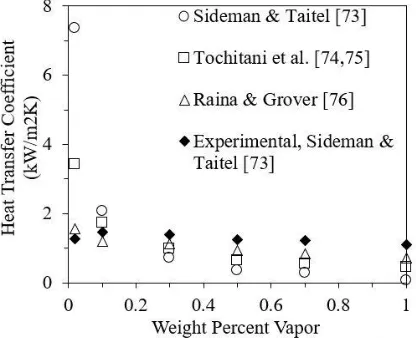
A seminal work on heat transfer in single droplet systems was conducted by Sideman
and Taitel [73]. The authors considered that a segment of the bubble is exposed to the bulk
liquid and the evaporating liquid covers the rest, forming a crescent shape around the
bubble. The net heat transfer coefficient expressed in terms of Nusselt number, Nu, was
found to be proportional to the initial volume of the droplet and was expressed as a function
of the bubble opening angle, θ, and Peclet number, Pe:
𝑁𝑢 = [(3 cos 𝜃 − cos3𝜃 + 2)/𝜋]0.5𝑃𝑒0.5 (13)
As the bubble grows, the volatile liquid shell becomes thinner and reduces the conduction
resistance across the shell. However, the model predicts very high heat transfer coefficients
during initial phases of bubble growth due to large liquid-liquid interface area. Tochitani
et al. [74,75] proposed a rigid sphere model where the liquid-liquid interface area was
Figure 13.Possible configurations of liquid-gas two phase bubbles. Redrawn
26
assumed to remain constant up to a vaporization ratio of 10% and reduced upon further
evaporation. Raina and Grover [76] introduced the effect of viscous shear on the spreading
of the dispersed phase over the bubble interface. Comparison between these models and
experimental data is shown in Figure 14. Contrary to Sideman and Taitel [73], a regression
analysis carried out by Battya et al. [77] showed that the Nusselt number is influenced by
the liquid temperature difference through Jakob number, Ja:
𝑁𝑢 = 0.64𝑃𝑒0.5𝐽𝑎−0.35 (14)
Haustein et al. [78] studied bubble growth in a two-phase droplet at high superheats through
sudden depressurization. They proposed a simplified model of bubble growth where a
liquid shell is present around the bubble until 30% evaporation, after which the shell is
assumed to rupture. Their droplet configuration is similar to that described by Sideman and
Taitel [73]. They identified three characteristic times during bubble growth relating
conduction heat transfer, convection heat transfer, and the shell rupture.
Avedisian and Suresh [79] developed a numerical model to predict bubble growth
rate when a bubble nucleates in a superheated droplet surrounded by an immiscible,
[image:43.612.221.429.424.593.2]superheated bulk liquid. The initial temperature of both liquids is assumed to be the same.
![Figure 4. Bubble passage through molten metal and slag commonly seen in metallurgy [16]](https://thumb-us.123doks.com/thumbv2/123dok_us/25010.1932/25.612.255.398.157.328/figure-bubble-passage-molten-metal-slag-commonly-metallurgy.webp)
![Figure 6. Schematic of typical spray column evaporator. Redrawn from [38].](https://thumb-us.123doks.com/thumbv2/123dok_us/25010.1932/27.612.234.456.464.694/figure-schematic-typical-spray-column-evaporator-redrawn.webp)