STRAIN AROUND A PLATFORM SWITCHED IMPLANT PLACED IN ANTERIOR MAXILLA-A FINITE ELEMENT ANALYSIS
Dissertation submitted to
THE TAMIL NADU Dr. M.G.R. MEDICAL UNIVERSITY In partial fulfillment for the degree of
MASTER OF DENTAL SURGERY
BRANCH – I
CERTIFICATE
This is to certify that the dissertation titled “EFFECT OF STRAIGHT AND
ANGULATED ABUTMENTS ON STRESS AND STRAIN AROUND A PLATFORM SWITCHED IMPLANT PLACED IN ANTERIOR MAXILLA-A FINITE ELEMENT ANALYSIS ” by Dr.Naveen kumar.T, post graduate student – MDS (Prosthodontics and Crown & Bridge- Branch- I ), ofKSR Institute of Dental Science and Research,
Tiruchengode, submitted to the TamilNadu Dr. M.G.R. Medical University, Chennai, in
partial fulfillment of therequirements for the MDS degree examination – April 2017- is a
bonafide researchwork carried out by him under our supervision and guidance.
GUIDED BY
DR.N. VIDYA SANKARI.MDS.
Professor,
Dept. of Prosthodontics and Crown Bridge, KSR Institute of Dental Science and Research,
Tiruchengode – 637 215.
Dr. C. A. MATHEW, M.D.S.,
Professor & Head of the Department, Dept. of Prosthodontics and Crown Bridge, KSR Institute of Dental Science and Research,
Tiruchengode – 637 215.
Dr. G.S. KUMAR M.D.S.,
Principal,
KSR Institute of Dental Science and Research,
DECLARATION BY THE CANDIDATE
TITLE OF DISSERTATION
Effect of straight and angulated abutments on stress and strain
around a platform switched implant placed in anterior maxilla-a
finite element analysis.
PLACE OF STUDY K.S.R. Insititute of Dental Science and Research
DURATION OF COURSE 3 Years
NAME OF THE GUIDE DR.N. VIDYA SANKARI
HEAD OF THE DEPARTMENT DR. C.A. MATHEW
I hereby declare that no part of the dissertation will be utilized for gaining financial assistance
for research or other promotions without obtaining prior permission of the Principal, K.S.R
Institute of Dental Science and Research, Tiruchengode. In addition, I declare that no part of
this work will be published either in print or electronic without the guide who has been
actively involved in the dissertation. The author has the right to reserve publishing of work
solely with prior permission of the Principal, K.S.R Institute of Dental Science and Research,
Tiruchengode.
I owe my deepest gratitude to God Almighty for all the blessings which he showers
upon me throughout my life and career.
I wish to express my heartfelt thanks to Thiru. Lion. K. S. Rangasamy, MJF, Founder and Chairman, K.S.R. group of institutions, for giving me an opportunity to undergo
post-graduation in this prestigious institution.
I am extremely grateful to Dr. G. S. Kumar., MDS, Principal, KSR Institute of Dental Science and Research for his invaluable guidance and constant support.
“A good teacher is a good mother”. I express my deep gratitude to my guide DR. N. Vidya Sankari, MDS, Professor, department of prosthodontics. KSRIDSR, for her motherly care. In fact, it was my good fortune to have a person who with sharp and concrete
suggestions at all junctures coupled with her tremendous knowledge, guided at all stages of
this difficult task. Often when I faced problems, which looked insurmountable, her moral
support gave me a lot of confidence without which this study would not have been
completed.
It is my privilege to express my regards to DR. C.A. Mathew, MDS, Professor & HOD, Department of Prosthodontics. KSRIDSR. . He has been a continuous source of
inspiration and I am indeed indebted to him for selflessly sparing me his time and knowledge
throughout my post graduate course. His encouragement and affectionate guidance will
always be remembered.
I also thank Dr S. Suresh Kumar MDS., Dr. J. Muthu Vignesh MDS., and Dr. M Maheshwaran MDS., Dr.Viswanathan.,MDS., and Dr. Raj Kumar MDS., for their relentless encouragement and continuous support throughout the course of my study. I am
deeply indebted to them for their most valuable suggestions which were instrumental in
many people to thank for listening to and, at times, having to tolerate me over the past three
years. I cannot begin to express my gratitude and appreciation for their friendship. Dr. Brindha, Dr.Mohammed, Dr.Benny Thomas, Dr.Mithrarajan, Dr.Satheesh, Dr.Uma maheshwari, Dr.Siva kumar, Dr.Yoganath, Dr. Sai Mahendran ,Dr. Kanmani ,Dr. Biju, Dr.Kasthoori and Dr.Shanmugapriya have been unwavering in their personal and professional support during my college hours.
I extend my heartfelt thanks to my friends, Dr.Sriram balagi , Mr.Vinosh kumar and Mr.shiva shanker for their help, advice and support.
I take this opportunity to thank all other faculties, lab technicians and non-teaching
staffs of the Department of Prosthodontics for their invaluable assistance and support
throughout my post-graduation course.
Parents are next to God, and their silent sacrifices for me can’t be put into words. I
S. No. TITLE PAGE No.
1. INTRODUCTION 1
2. AIMS AND OBJECTIVES 4
3. REVIEW OF LITERATURE 5
4. MATERIALS AND METHODS 15
5. RESULTS 28
6. DISCUSSION 50
7. SUMMARY AND CONCLUSION 60
TABLE No. TITLE PAGE No.
1.
(a):Number of elements and nodes
(b) :Material properties used in FEA Study 23
2.
The value of von Mises stress for the models with platform
switched abutments.(units in Mpa) 30
3.
The value of von Mises stress for the models with platform
switched abutments.(units in Mpa). 30
4.
The value of von Mises strain for the models with platform
switched abutment in micro strains (strain × 10 -6 ). 31
5.
The value of von Mises strain for the models with platform
GRAPH No. TITLE PAGE No.
1.
Bar diagram showing stress values (in Mpa) with in cortical
bone around the implant 32
2.
Bar diagram showing stress values (in Mpa) with in cancellous
bone around the implant 32
3.
Bar diagram showing strain values (in micro strains)with in
cortical bone around the implants 33
4.
Bar diagram showing strain values (in micro strains) with in
FIGURE NO. TITLE PAGE NO.
1.
A. Dimension of Implant
24
B. Bone model with implant and platform matched straight
abutment
24
2.
A. PS 0-an implant fixture (4.3mm) with platform switched 0°
(3.5 mm) straight abutment .
25
B. PS 15- an implant fixture (4.3mm) with platform switched
15° (3.5 mm) angulated abutment .
25
C. PS 20 - an implant fixture (4.3mm) with platform switched
20°(3.5 mm) angulated abutment .
26
D.PS 25 - an implant fixture (4.3mm) with platform switched 25°
(3.5 mm) angulated abutment .
26
3.
FEM mesh created by an analyst prior to finding a solution to a
problem using FEM software
27
4. A&B
Pictorial representation of stress values in straight abutment for
axial load
34
5. A&B
Pictorial representation of stress values in straight abutment for
off-axis load.
for axial load.
7. A&B
Pictorial representation of stress values in 15° angled abutment
for off-axis load
37
8. A&B
Pictorial representation of stress values in 20° angled abutment
for axial load.
38
9. A&B
Pictorial representation of stress values in 20° angled abutment
for off-axis load
39
10.A&B
Pictorial representation of stress values in 25° angled abutment
for axial load
40
11.A&B
Pictorial representation of stress values in 25° angled abutment
for off-axis load
41
12.A&B
Pictorial representation of strain values in straight abutment for
axial load.
42
13.A&B
A pictorial representation of strain values in straight abutment for
off-axis load.
43
14.A&B
Pictorial representation of strain values in 15° angled abutment
for axial load.
44
15.A&B
A pictorial representation of strain values in 15° angled abutment
for off-axis load.
45
16.A&B
Pictorial representation of strain values in 20° angled abutment
for axial load.
for off-axis load
18.A&B
Pictorial representation of strain values in 25° angled abutment
for axial load.
48
19.A&B
Pictorial representation of strain values in 25° angled abutment
for off-axis load
Page 1 INTRODUCTION
Dental implants are considered as one of the most successful treatment options
for replacing missing teeth after discovery of the osseointegration concept by Branemark in
the 1950s1. After the loss of teeth there will be a substantial amount of change in the
morphology of alveolar bone. After extraction in the anterior maxillary region there will
almost be twice the amount of horizontal bone resorption when compared to the vertical bone
resorption2.
This situation can be managed either by surgical management or by placing
implants in areas of maximum bone availability. This change in implant angulation can be
managed by placing angulated abutments during prosthetic rehabilitation and it is considered
as a valid treatment option3,4 .
The success of an implant restoration greatly depends upon the success of the
osseo integration. However crestal bone loss is observed after implant placement. Adell et al5
first reported the crestal bone loss by a retrospective 15 year study. A marginal bone loss of
1.5mm is evident from first thread during healing and in the first year after loading was noted
from his study. Thereafter an average 0.1mm bone loss was noted annually.
To minimize the marginal bone loss and for better esthetic outcome, platform
switched implants were introduced over conventional platform matched implants. In
conventional platform matched implants the abutment diameter is matched with the implant
diameter. In platform matched implant both the implant diameter and abutment diameter are
Page 2
Platform switching concept implies the use of under sized prosthetic platform
than the implant platform. The prosthetic platform is shifted inwards from the perimeter of
implant platform, thereby creating a step, or angle, between the implant and abutment6.
The implant abutment junction (IAJ) in platform matched implant will be along
the implant perimeter, but in platform switched implants the IAJ gets shifted medially from
the implant perimeter. The micro gap between the implant and abutment in the IAJ harbors
lot of micro organisms which in turn leads to the collection of inflammatory cell infiltrate
(ICT) around the IAJ .This ICT leads to bone loss of 1.5mm around IAJ.As the IAJ gets
shifted medially in platform switched implants the bone loss will be coronal compared with
platform matched implants.
Implant manufacturers have introduced pre angled abutments available from 15°
to 35°.Custom made abutments can also be fabricated according to the individual situations.
Many clinical comparative studies have showed no significant difference in bone
loss and survival rates between platform matched straight and angled abutment3,7,8,9.How ever
the photo elastic studies and strain gauge measurements 10 and finite element analyses11
revealed that platform matched angled abutment are subjected to more stress. Finite element
analysis by Xavier et al12 suggests that there was 15 % more strain in platform matched
straight abutments than platform matched angled abutments.
There are only few investigators who compared the straight and angulated
abutment conditions with respect to platform switched implant13,14,15.A finite element
analysis by martini et al 13 states that implants with platform switched straight abutment
generates the highest stress value, but another study shows that platform switched angulated
Page 3
So far investigators have included only straight and 15° angled platform switched
abutments for their study. They have not included platform switched angled abutments with
more than 15°, but in clinical situations we may have to use more the 15° angulated
abutments, for better esthetic outcome. The purpose of the present study is to compare the
effect of straight (0°) and abutments of various degree angulation (15°, 20°, 25°) on stress
and strain distribution around a platform switched implant using three dimensional finite
Page 4
AIM
The aim of the present study is to compare the effect of straight (0°) and angulated abutments
(15°, 20°, 25°) on stress and strain distribution around a platform switched implant placed in
the anterior maxilla using three dimensional finite element analysis.
OBJECTIVES
The objectives of the present study are
1.To evaluate the von Mises stress and strain values in the cortical and cancellous bone,
around platform switched implants with straight abutments (0°) and abutments with various
angulations (15°,20°,25°).
2. To compare the von Mises stress and strain values between the cortical and cancellous
bone, around the platform switched implants with various angulations (0°,15°,20°,25°).
3.To compare the von Mises stress and strain values in cortical bone and cancellous, around
the platform switched implants between various abutment angulations (0°,15°,20°,25°).
4.To compare the von Miss stress and strain values around the implants in all of the above
mentioned conditions with 0° on axis load of 178 N along the long axis of abutment and
Page 5 REVIEW OF LITERATURE
Atwood 22 in 1962 explained the physiology behind the resorption of residual alveolar ridges. Atwood concluded that the rate of resorption of alveolar ridges varied among different
individuals. The factors related to the rate of resorption are divided in to anatomic, metabolic,
functional and prosthetic factor.
Adell et al 5 in 1981 studied the osseointegration of implants placed in both edentulous maxilla and mandible. They followed the patients for 15 years and concluded that the mean
marginal bone loss after the first year of implant placement was 1.5mm.There after 0.1 mm of
bone was lost annually.
Charles A. Babbush ,and Mari Shimura,23 in 1993 evaluated patients who were treated with IMZ system for five years. With statistical and clinical observation, they concluded that
larger diameter implants had higher survival rates than small diameter implants. The implants
in maxilla had lower survival rate than implants in the mandible.
Nancy L. Clelland, Amos Gilat, Edwin. McGlumphy, William A. Brantley 35 in 1993 conducted a photo elastic study and strain gauge measurements to determine the level of
stress and strain for angulated abutments. They concluded that there was a significant
increase in stress and strain for each, with increase in abutment angulation. Highest stresses
Page 6 Nancy L. Clelland, DMD, MSD, K. Lee, Olivier C. Bimbenet, MS, and William A. Branthy36 in 1995 studied the effect of abutment angulation on stress and strain around the implant using finite element study. They concluded that there was an increase in magnitude
of stress and strain as the abutment angulation increased.
Cany et al 11in 1996 studied the stress distribution around the vertical and angled implant with finite element study. They concluded that the angled implant showed more stress around
the implant in the cervical region.
George Papavasiliou, Phophi Kamposiora,Stephen C. Bayne, and David A. Felton 31 in 1996 did finite element analysis on stress distribution around single tooth implants and
concluded that there were no differences between types of veneering materials and the
absence of cortical bone increased the inter facial stresses. Oblique load increased stress by
15 times than axial load.
Balshi et al 7 in 1997 studied about the clinical outcome of angulated abutments. They used angulated abutments and a combination of angled and standard abutments on 71 patients and
did a follow up for 3 years. They concluded that angulated abutments showed good
preliminary results and should be compared to the standard abutment as a predictable
Page 7 Brosh et al 10 in 1998 compared two experimental techniques for analyzing stress and strain around implants. According to the author strain gauges were reliable to study the strain
around the implants, where as a photo elastic study can be regarded as a complimentary
method. They concluded that strain values were more for angled abutments than straight
abutments.
Ashok et al 3 in 2000 studied about the clinical success of angulated abutments between 0° to 45° .He concluded that angled abutments can be comfortably used in situations with
compromised bone. The esthetic and functional outcome was satisfactory. There was no
significant difference between the clinical outcome of straight and angulated abutments.
Dorthy et al 4 in 2000 compared the success of implants placed with standard and angulated abutments. They compared the parameters like probing depth, gingival level, gingival index,
and mobility. They concluded that there was no significant difference in those parameters
between standard and angulated abutments. So it was suggested that angled abutments could
be a suitable restorative option.
Geng et al 16 in 2001 reviewed that Finite element analysis (FEA) has been used extensively to predict the biomechanical performance of various dental implant designs as well as the
effect of clinical factors on implant success. This article reviewed the current status of FEA
applications in implant dentistry and discussed findings from FEA studies in relation to the
Page 8 Rickard Brånemark,P-I Brånemark,Björn Rydevik, Robert R. Myers 1 in 2001 reviewed about the concept of osseointegration and attempted to highlight the key developments in the
research and application of osseointegration. In this article the author defines osseointegration
and osseoperception. He explains in detail about the clinical applications of osseointegration.
Kaus et al 8 in 2002 described the concept of evaluation of angulated abutments ,which was originally developed first for the external hex implants .Then the concept was evolved to use
in internal hex Morse taper connections .Authors have conducted a study for 151 months
and total of 3101 implants were placed with 0 degree to 45 degree angled abutments. They
concluded that the clinical out come of implants with angulated abutments were satisfactory
and could be successfully used in implant rehabilitation.
Seivimay et al 20 in 2005 studied about stress concentrations around implant supported crowns in different bone qualities .Authors concluded that among the different qualities of
bone D3 and D4 bone produced more stress around the implant. The highest stress
concentration was at the in neck of the bone.
Richad.J.Lazzara,Stephan.S.Porter28in 2006 reviewed about the biological dimensions of
hard and soft tissues around platform switched dental implants. Authors concluded that there
were many advantages in platform switched implants over platform matched implants and
Page 9 Jivraj et al 2 in 2006 explained the challenges in implant rehabilitation of the maxilla. They stated that the amount and quality of available bone will be less after extraction of teeth in the
maxilla. Further esthetic concern is also an important .This article has compared the different
treatment options available for treatment of edentulous maxilla and explained about the
importance of diagnosis and treatment planning in such situations.
Xavier et al12 in 2007 studied the effect of abutment angulation on the strain on the bone around an implant in the anterior maxilla. He concluded that the strain values were 15%
higher in implants placed with straight abutments compared to the implants with angulated
abutment.
Ming-Lun Hsu, Fang-Ching Chen,Hung-Chan Kao, Cheng-Kung Cheng 24 in 2007 conducted a finite element analysis on off-axis loading and concluded that to achieve a
favourable prognosis, axial loading is recommended. Off-axis loads produce more stress than
vertical loads.
Jose Henrique Rubo, Edson Antonio Capello Souza32 in 2008 conducted a finite element study to find the stress distribution around the dental implants. They concluded that the stress
distribution was better with stiffer bone, longer abutments and implants with shorter
cantilevers. The use of co-cr alloy framework appears to contribute to better stress
Page 10 Hung-Chan Kao, Yih-Wen Gung,Tai-Foong Chung,Ming-Lun Hsu, Dr Med Dent33in 2008 investigated the micromotion between the implant and surrounding bone caused by the
implementation of an angled abutment for an immediately loaded single dental implant
located in the anterior maxilla and concluded that abutment angulation up to 25 degrees can
increase the stress in the peri-implant bone by 18% and the micromotion level by 30%.
Chun-Li Lin, Jen-Chyan Wang, Lance C. Ramp, Perng-Ru Liu34 in 2008 studied the
biomechanical response of implant system placed in the maxillary posterior region and
concluded that better stress/strain distribution is possible when implants are placed along the
axis of loading with good cortical contact.
Francesco Carinci ,Giorgio Brunelli, Matteo Danza30in 2009 studied about the bone platform switching and conventional implants. Bone platform switching involves an inward
bone ring formation in coronal part of implants, obtained by using a dental fixture with
reverse conical neck. They concluded that there was no difference in survival and success
rates between conventional vs reverse conical neck implant.
Matteo Danza et al 39 in 2009 concluded that lowest stress value was found in the system with straight abutment loaded with vertical force while highest stress value was found in
implants with 15° angulated abutment loaded with angulated force.
Cavallaro et al 9 in 2011reviewed the usage of angled abutments in implant rehabilitation. They concluded that angled abutments not only had satisfactory clinical outcome, but they
Page 11
Chun-Yeo Ha, Yung-Jun Lim, Myung-Joo Kim, Jung-Han Choi 37in 2011 compared the
removal torque values of different abutments(straight, angled and gold premachined
UCLA-type) in external and internal hex implants after dynamic loading with clinical situation of the
anterior maxilla. They concluded that there was no significant difference in removal torque
value of internal hex implants.
Haibin, Zhiyong, Jinxin, Tao, Zaibo, Chuncheng 27 in 2011 compared the stress
distribution of non platform switched and platform switched abutment for implants supported
single crown with finite element analysis and concluded that when platform switched
abutment were used, the maximum Von mises stress with the surrounding bone was lower.
However, this value is higher with in the fixture and screw.
Alper Gultekin, Pinar Gultekin and Serdar Yalcin21 in 2012 explained in detail about the application of finite element analysis in implant dentistry. They explained in detail about the
basics of finite element analysis and steps in analysing the stress strain pattern in detail.
Paula et al13 in 2012 studied about the stress around the platform switched straight abutment and platform switched angled abutment with finite element analysis .They concluded that
platform switched straight abutment showed more stress around the implant than the platform
switched angled abutments. Further they stated that oblique load increased the stress than
Page 12 Rohit Bahuguna et al 25 in 2013 evaluated the stress pattern in bone around dental implants .Authors found that as the abutment angulation increased from 0° to 20°both compressive and
tensile stresses also increased around the implants.
Angel Alvarez-Arenal, Luis Segura-Mori,Ignacio Gonzalez-Gonzalez, Angel Gago 26 in
2013 concluded that platform switching reduced the stress values on the abutment and
retention screw. The stress on abutment screw gradually increased as the loading direction
changed from vertical to oblique.
Kumar et al19 in 2013 studied about stress distribution around implants with straight and angulated abutments in different bone qualities and concluded that angled abutments
produced more stress than straight abutments. The stress in D4 quality bone was more when
compared to D1 quality bone .The high stress in the angled abutment at the cervical zone was
due to forces and momentum around the cortex.
Paul, et al 15in 2013 studied about the strain generated in bone by platform switched and non platform switched implants with straight and angulated abutments under vertical and
angulated load with finite element analysis. The results of this investigation indicated that the
ideal values of microstrain (50-3000 microstrain) could be exhibited by platform switching of
dental implants (with an abutment–implant diameter difference of 1 mm) and could be
considered as a better alternative for prevention of crestal bone loss when compared to non–
Page 13 Martini et al 14 in 2013 have done a finite element study to find out the influence of platform switching and angulated abutments on surrounding bone. They concluded that platform
switched implant showed less stress in cortical bone around the fixture head than platform
matched implants. Further angulated abutments showed more stress than straight abutments.
Kalavathy et al6 in 2014 reviewed the concept of platform switching in implants. They described about the factors that could lead to crestal bone loss. According to the authors
platform switching concept effectively reduced the crestal bone loss by reducing the stress
around the bone and shifting the implant abutment junction medially towards the centre of the
implant. There by the biological width of 1.5 mm could be maintained with reduced crestal
bone loss.
Pradeep Bholla, Liju Jacob Jo1, Kalepu Vamsi, Padma Ariga 38 in 2014 conducted a finite element study about the stress pattern at bone implant interface by angulated abutments.
They concluded that von mises stresses were more concentrated in cortical bone and more
stress was seen in the crestal region. When the angulations were increased the stress around
the implants also increased .Oblique loads increased the stress around implants than vertical
Page 14 Yousuf Aseel KP, SripathiRao BH , Hassan Sarfaraz , Joyce Sequiera , Gunachandra Rai , Jagadish Chandra 29 in 2015 studied radiographically about the crestal bone loss around platform shifted and non platform shifted implants. They concluded that there was a
significant difference between the crestal bone loss among the two types of implants after 6
months of functional loading. Platform switched implants produced less bone loss than non
platform switched implants.
Mohamed A. Elsadek , Hesham A. Katamesh and Hanaa I. Sallam40 in 2016 evaluated sthe effect of implant platform switching on strain developed around implants with straight
and angulated abutments using strain meter. They concluded that straight implants with
Page 15
MATERIALS AND METHODS
A three dimensional finite element study was under taken to create model and
analyse the situation. Finite element analysis was chosen to do this to determine the stress and
strain around the dental implant and to study the mechanical behavior of complex structures
easily by dividing the complex structures in to numerous small simple structures16.
Bone model
Lekholm and Zarb17 have explained the classification system of bone as follows:
Based on its radiographic appearance and the resistance at drilling, bone quality has been
classified in four categories:
Type 1(D1) bone -the entire bone is composed of homogenous compact bone;
Type 2(D2) bone -a thick layer of compact bone surrounds a core of dense trabecular bone;
Type 3(D3) bone -a thin layer of cortical bone surrounds a core of dense trabecular bone; and
Type 4(D4) bone -a thin layer of cortical bone surrounding a core of low density trabecular bone of poor strength. These differences in bone quality can be associated with different
areas in the upper and lower jaw.
In this study the bone properties approximating those of D3 bone was used since 65% of bone
found in the premaxillae is of D3 type12
Maxillary bone was modelled as a section simulating the pre maxillary area with
cortical bone thickness of 1.5 mm enclosing the trabecular bone core.
The bone block was modelled with 18 mm height from base to crestal bone and 8
Page 16 Implant model
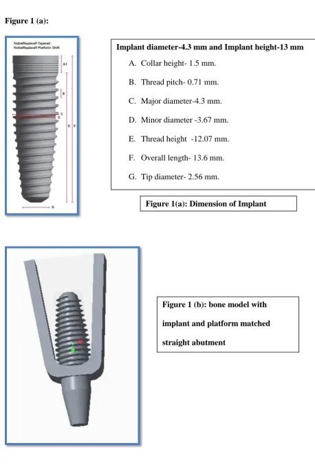
A solid tapered, screw type ,root form , commercially pure titanium implant of 13
mm length and 4.3 mm diameter is modelled and simulated to be placed in thesection of
bone 15[Figure 1]. The dimensions of implant fixture including thread design and pitch were simulated with Noble Replace platform switching implants (Noble replace, Nobel Biocare,
Goteborg, Sweden). The dimensions were obtained by the noble replace implant manual18.
The implant was modelled with collar diameter of 4.3 mm and tip diameter of
2.56mm.Collar height was designed as 1.5 mm and thread height is of 12.07 mm. The pitch
of the thread is of 0.71 mm.
Straight abutments(0°) and angulatedabutments (15°,20°,25°) of 3.5 mm
(platform switched) diameter are simulated with 10° occlusal taper and 7 mm.
Three dimensional finite element models were constructed for the following
configurations.
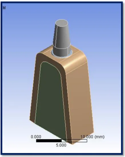
PS 0-an implant fixture (4.3mm) with platform switched 0° (3.5 mm) straight abutment
(figure 2 a).
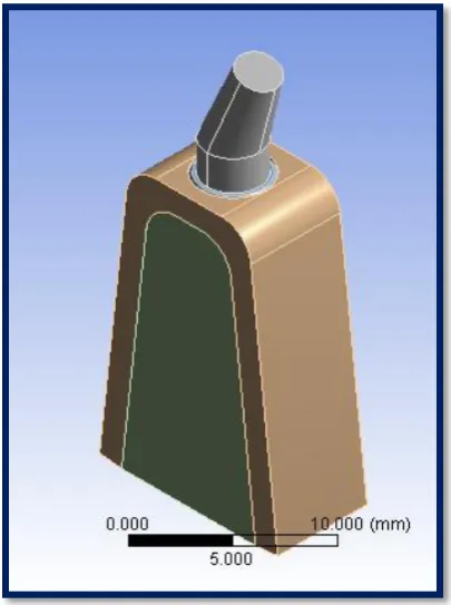
PS 15-an implant fixture (4.3mm) with platform switched 15° (3.5 mm) angled abutment
(figure 2 b).
PS 20-an implant fixture (4.3mm) with platform switched 20° (3.5 mm) angled abutment
(figure 2 c).
PS 25-an implant fixture (4.3mm) with platform switched 25° (3.5 mm) angled abutment
(figure 2 d).
Page 17
Each of these implants were placed in four simulated premaxillary models of D3
bone quality.
Three dimensional models of the implant, bone and abutments have been
fabricated using Pro/Engineer Wildfire 2.0 software (Parametric Technology Corp, Needham,
MA, USA).Thus total numbers of four simulated premaxillary models with different
abutment angulations for platform switched implants were generated.
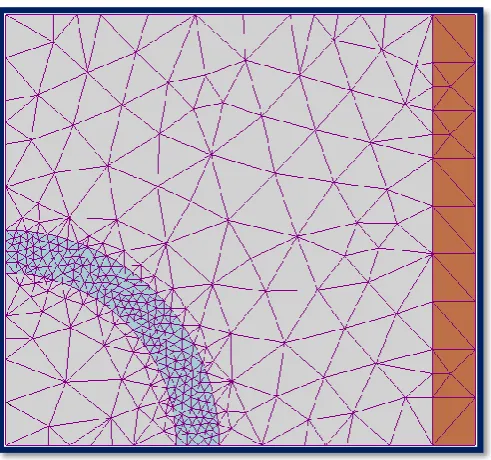
The analysis was performed using the software ANSYS Workbench 15.0(Santa
Monica, CA, U.S.A).The models were processed with ANSYS to generate a meshed
structure. Meshing divides the entire model in to smaller elements which are interconnected
at specific joints called nodes. The default number of elements and nodes used for each
model is shown in Table 1(a).
All the materials used in the models were considered to be isotropic,
homogenous, and linearly elastic. The osseointegration of implant was accepted as 100%.
Since there are no universally accepted properties of the biologic materials available in the
literature, a mean value of the material properties has been used in the present study19,20 and
have been tabulated in Table 1(b).
Young's modulus is the ratio of stress (which has units of pressure) to strain (which is dimensionless), and so Young's modulus has units of pressure. Its SI unit is
therefore the pascal (Pa ). The practical units used are megapascals (MPa) or gigapascals
(GPa).
Poisson's ratio is the ratio of transverse strain to axial strain. In other words, Poisson`s ratio is the amount of transversal expansion divided by the amount of axial
Page 18
A simulated on axis load of 178N was applied at the centre of incisal edge, along
the long axis of each abutment and a simulated off-axis load of 178 N was applied at the
centre of incisal edge, 45° to the long axis of the abutment.
The amount of load selected in this study is based on the literature on average
biting force for incisors12,19. The forces applied were static and von mises stress values
around the implants were recorded.
In finite element analysis overall stress state at a point are summarized with von
Mises stresses. All the materials including cortical bone, trabecular bone, titanium implant
and titanium abutment were assumed to be linear, elastic, homogenous and isotopic.19, 20.
BASIC CONCEPT OF FINITE ELEMENT ANALYSIS
Finite element analysis is a practical application of finite element method, which
is used by researchers and scientists to create a complex mathematical problem and to solve
the problem by dividing the complex problem domain into numerous simple
domains(elements) and numerically solving the problem.
Finite element analysis was first introduced in aerospace industry in 1960s to
solve structural problems. In late 1980s it was introduced to implant dentistry by
Weinstein16,21.
In finite element method the actual complex structure is divided in to numerous
small simple structures called as finite elements. The finite elements are the divided, smaller
and simpler parts of a complex domain. These elements inside the actual complex structure
are inter connected by numerous nodes. The collection of numerous elements and nodes
Page 19
The nodes lie on the boundary of the elements where adjacent elements are
connected. After meshing the next process is to define the boundary condition. In structural
analysis, boundary conditions are applied to the regions of the model where the
displacements and/or rotations are known21. Such regions may be designed to remain fixed
(have zero displacement and/or rotation) during the simulation or may have
specified,non-zero displacements and/or rotations. The directions along which motion is possible are called
degrees of freedom21.
The process of creating the mesh, elements and their respective nodes, and
defining boundary condition is termed as “discretization” of the problem domain. Then the
mechanical properties of desired materials are incorporated in the mesh to create a working
model.
After meshing and defining the boundary condition of the model, the loads to be
Page 20 FUNDAMENTALS OF DENTAL IMPLANT BIOMECHANICS IN FEA
Photoelasticity is a method to determine the stress distribution in a material experimentally. The method is mostly used where mathematical methods become quite
difficult. Unlike the analytical methods of stress determination, photoelasticity gives a fairly
accurate picture of stress distribution around discontinuities in materials. The method is an
important tool for determining critical stress points in a material, and is used for determining
stress concentration in irregular geometries. But it does not give accurate stress value at a
point.
A strain gauge is a device used to measure strain on an object. The strain gauge consists of an insulating flexible backing which supports a metallic foil pattern. The gauge is
attached to the object by a suitable adhesive. As the object is deformed, the foil is deformed,
causing its electrical resistance to change. This resistance change, usually measured using a
Wheatstone bridge, is related to the strain by the quantity known as the factor. But this method is not so accurate because numerous factors like temperature, humidity and
permanent deformation of material will affect the results and reproducibility of this method.
Since dental implant –bone system is considered as a complex structure, finite element method is used to mathematically model the system. Finite element analysis has been found to be the most suitable and predictable tool to evaluate the effect of stress and
Page 21
Finite element analysis has some advantages than other methods (photo elastic
analysis, strain gauge analysis) of stress analysis. They are
1. It is a non invasive technique.
2. The alveolar bone, tooth and the implant can be simulated according to the
material properties of these structures in order to achieve nearest possibly simulating in vitro
oral conditions
3. The actual stress experienced at any point can be measured.
4. Graphical visualisation of the actual implant displacement is possible.
5. Reproducibility does not affect the physical properties of involved materials and the study
can be repeated to any number of times.
Page 22 ARMAMENTARIUM
1. INTEL CORE i3-PROCESSOR
2.2.13 GHZ SPEED
3.3 GB RAM
4.320 GB HARD DISC DRIVE
5.52 x CD ROM
6.15 INCH COLOUR MONITOR
7. WINDOWS 10.64 -BIT BASED PROCESSOR
8. PRO-ENGINEERING WILD FIRE SOFTWARE
9. ANSYS WORKBENCH 15.0 FINITE ELEMENT SOFTWARE
10. KEY BOARD
Page 23 Table 1(a):Number of elements and nodes
Models Elements Nodes
PS 0 2239 6351
PS 15 2335 6756
PS 20 2366 6916
PS 25 2299 6588
Table 1 (b) :Material properties used in FEA Study
Material Youngs Modulus(GPa) Poisons ratio
Titanium abutment & implant 110 0.35
Dense trabecular bone (D1,D2&D3)
1.37 0.3
Low density trabecular bone (D4 Bone)
1.10 0.3
Page 24 Figure 1 (a):
Implant diameter-4.3 mm and Implant height-13 mm
A. Collar height- 1.5 mm.
B. Thread pitch- 0.71 mm.
C. Major diameter-4.3 mm.
D. Minor diameter -3.67 mm.
E. Thread height -12.07 mm.
F. Overall length- 13.6 mm.
G. Tip diameter- 2.56 mm.
Figure 1(a): Dimension of Implant fixture.
[image:42.595.65.524.62.740.2]Page 25 FIGURE 2 (A): PS 0- AN IMPLANT FIXTURE (4.3MM) WITH PLATFORM SWITCHED 0° (3.5 MM) STRAIGHT ABUTMENT.
[image:43.595.71.290.84.358.2] [image:43.595.72.555.89.745.2]Page 26 FIGURE 2 (C): PS 20 - AN IMPLANT FIXTURE (4.3MM) WITH PLATFORM SWITCHED 20° (3.5 MM) ANGULATED ABUTMENT.
[image:44.595.66.551.80.755.2] [image:44.595.71.274.85.357.2]Page 28
RESULTS
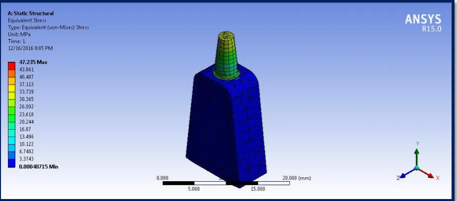
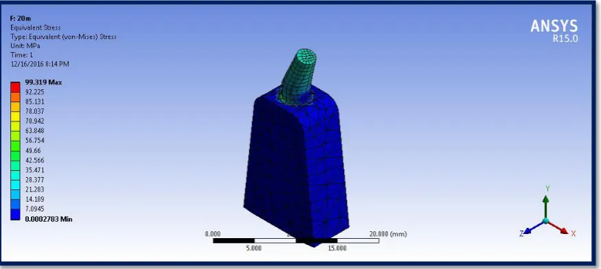
Stress distribution was represented numerically and it was colour coded. The maximum von
Mises stress around the platform switched straight abutment for axial load was 12.79 Mpa
and maximum von Mises stress value was increased with increase in abutment angulation
(Table-2). The maximum value around platform switched 25°abutments for axial load was recorded as 40.12 Mpa. The von Mises stress value around the platform switched implant in cancellous bone follows the same pattern and was less when compared with cortical bone, the
values ranged between 0.60 Mpa (for straight abutment) to 1.12 Mpa (for 25° angled abutment) (Table-3).
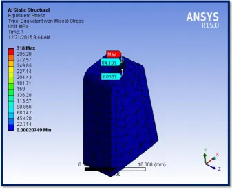
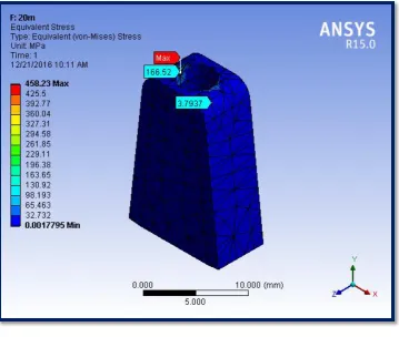
The maximum von Mises stress around the platform switched straight abutment for 45°
off-axis load was 84.13 Mpa and maximum von Mises stress value was increased with increase in abutment angulation (Table-2). The maximum value around platform switched
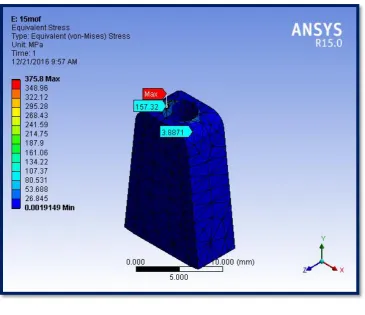
25°abutments for axial load was recorded as 157.32 Mpa. The von Mises stress value around the platform switched implant in cancellous bone followed the same pattern and was less
when compared with cortical bone, the valued ranges between 2.03 Mpa (for straight abutment) to 4.44 Mpa (for 25° angled abutment) (Table-3).
The maximum von Mises strain value for cortical bone in platform switched abutments for
axial load increased with increase in abutment angulation. Strain has no unit, but it can be
converted in to microns (10-6 ) and expressed as microstrains, the microstrain value ranged
between 882 micro strains for straight abutment to 3220 microstrains for 25 ° abutment.
Page 29
The Maximum von Mises strain value in off-axis loading for platform switched abutments
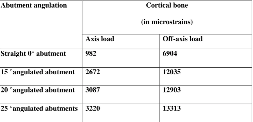
increased with increase in abutment angulation and ranged between 6904 microstrains for straight abutment to 13313 microstrains for 25° abutment (Table 4).The strain value for cancellous bone was less when compared to cortical bone and ranged between 1505 microstrains for straight abutment and 3154 microstrains for 25° angulated abutments.
(Table 5).
The maximum von Mises stress and strain values for platform switched implant with 45°
off-axis load increased several folds when compared to platform switched implant with axial load
for all abutment angulations.
Page 30
Table -2
The value of von Mises stress for the models with platform switched abutments.(units in Mpa)
Abutment angulation Cortical bone (in Mpa)
Axis load Off-axis load
Straight 0° abutment 12.79 84.13
15 °angulated abutment 24.66 157.32
20 °angulated abutment 34.07 166.52
25 °angulated abutments 40.12 175.48
Table -3
The value of von Mises stress for the models with platform switched abutments.(units in Mpa).
Abutment angulation Cancellous bone (in Mpa)
Axis load Off-axis load
Straight 0° abutment 0.60 2.03
15 °angulated abutment 0.88 3.88
20 °angulated abutment 1.01 3.79
Page 31
Table -4
The value of von Mises strain for the models with platform switched abutments in micro strains (strain × 10 -6 ).
Abutment angulation Cortical bone
(in microstrains)
Axis load Off-axis load
Straight 0° abutment 982 6904
15 °angulated abutment 2672 12035
20 °angulated abutment 3087 12903
[image:50.595.71.489.171.373.2]25 °angulated abutments 3220 13313
Table -5
The value of von Mises strain for the models with platform switched abutments in micro strains (strain × 10 -6 ).
Abutment angulation Cancellous bone
(in micro strains)
Axis load Off-axis load
Straight 0° abutment 448 1505
15 °angulated abutment 677 2562
20 °angulated abutment 755 2787
Page 32 Bar diagram showing stress values (in Mpa) with in cortical bone around the implant
Bar diagram showing stress values (in Mpa) with in cancellous bone around the implant
0 20 40 60 80 100 120 140 160 180
0 °abutment 15° abutment 20°abutment 25°abutment
12.79
24.66 34.07
40.12
84.13
157.32 166.52
175.48 axial load off-axis load 0 0.5 1 1.5 2 2.5 3 3.5 4 4.5
0 ° abutment 15°abutment 20°abutment 25°abutment
0.6
0.88 1.01
1.12 2.03
3.88 3.79
4.44
axial load
Page 33 Bar diagram showing strain values (in micro strains) with in cortical bone around the implants
Bar diagram showing strain values (in micro strains) with in cancellous bone around the implants 0 2000 4000 6000 8000 10000 12000 14000
0 ° abutment 15 °abutment 20° abutment 25 °abutment
982
2672 3087 3220
6904
12035
12903 13313
axial load off-axis load 0 500 1000 1500 2000 2500 3000 3500
0 °abutment 15 °abutment 20° abutment 25° abutment
448
677 755 809
Page 34 FIGURE 4 A: PICTORIAL REPRESENTATION OF STRESS VALUES IN
STRAIGHT ABUTMENT FOR AXIAL LOAD.
[image:53.595.73.430.429.718.2]Page 35 FIGURE 5 A :PICTORIAL REPRESENTATION OF STRESS VALUES IN
STRAIGHT ABUTMENT FOR OFF-AXIS LOAD.
Page 36 FIGURE 6 A :PICTORIAL REPRESENTATION OF STRESS VALUES IN 15°
ANGLED ABUTMENT FOR AXIAL LOAD.
Page 37 FIGURE 7 A: PICTORIAL REPRESENTATION OF STRESS VALUE IN 15°
ANGLED ABUTMENT FOR OFF-AXIS LOAD.
Page 38 FIGURE 8 A :PICTORIAL REPRESENTATION OF STRESS VALUES IN 20°
[image:57.595.77.515.141.337.2]ANGLED ABUTMENT FOR AXIAL LOAD.
Page 39 FIGURE 9A :PICTORIAL REPRESENTATION OF STRESS VALUES IN 20°
ANGLED ABUTMENT FOR OFF-AXIS LOAD.
Page 40 FIGURE 10A :PICTORIAL REPRESENTATION OF STRESS VALUES IN 25°
[image:59.595.77.442.416.720.2]ANGLED ABUTMENT FOR AXIAL LOAD.
Page 41 FIGURE 11 A:PICTORIAL REPRESENTATION OF STRESS VALUES IN 25°
[image:60.595.76.385.140.392.2]ANGLED ABUTMENT FOR OFF-AXIS LOAD.
Page 42 FIGURE 12 A :PICTORIAL REPRESENTATION OF STRAIN VALUES IN
STRAIGHT ABUTMENT FOR AXIAL LOAD.
[image:61.595.76.442.462.755.2]Page 43 FIGURE 13: A PICTORIAL REPRESENTATION OF STRAIN VALUES IN
STRAIGHT ABUTMENT FOR OFF-AXIS LOAD.
[image:62.595.74.428.443.728.2]Page 44 FIGURE 14 A PICTORIAL REPRESENTATION OF STRAIN VALUES IN 15°
ANGLED ABUTMENT FOR AXIAL LOAD.
[image:63.595.72.427.439.726.2]Page 45 FIGURE 15 :A PICTORIAL REPRESENTATION OF STRAIN VALUES IN 15° ANGLED ABUTMENT FOR OFF-AXIS LOAD.
[image:64.595.76.427.441.730.2]Page 46 FIGURE 16 A :PICTORIAL REPRESENTATION OF STRAIN VALUES IN 20° ANGLED ABUTMENT FOR AXIAL LOAD.
[image:65.595.75.415.441.723.2]Page 47 FIGURE 17 A :PICTORIAL REPRESENTATION OF STRAIN VALUES IN 20° ANGLED ABUTMENT FOR OFF-AXIS LOAD.
[image:66.595.75.413.441.727.2]Page 48 FIGURE 18 A :PICTORIAL REPRESENTATION OF STRAIN VALUES IN 25° ANGLED ABUTMENT FOR AXIAL LOAD.
[image:67.595.73.473.428.754.2]Page 49 FIGURE 19 A :PICTORIAL REPRESENTATION OF STRAIN VALUES IN 25° ANGLED ABUTMENT FOR OFF-AXIS LOAD.
Page 50 DISCUSSION
The close relationship between the tooth and alveolar process continues
throughout life. Wolff’s law (1892) states that bone remodels in relation to the forces applied.
Every time the function of bone is modified, a definite change will occur in the internal
architecture and external configuration17.
The greater the magnitude of stress applied to the bone, greater will be the strain
observed. Bone modelling and remodeling are primarily controlled by the mechanical
environment of the strain. The density of alveolar bone evolves as a result of mechanical
deformation from the microstrain. In the theory of mechanostat, H. M. Frost15 proposed that
the bone mass is the direct result of the mechanical usage of skeleton. A model of four zones
for the compact bone as related to mechanical adaptation to the strain has been proposed: The
pathologic overload zone (greater than 3000 microstrain), mild overload zone (1500-3000),
adapted window (50-1500), and acute disuse window (0-50). Crestal bone loss will be often
evidenced during the early implant loading, as the result of bone in the pathologic overload
zone (excess stress and strain at the implant–bone interface). Stress is seen to be greatest at
the crest, compared with other regions in the implant body. An optimum strain environment
will exist for each specific anatomical area and the peak strains innate for that area should be
maintained to optimize the bone’s response15
.
Bone resorption is a common phenomenon in the residual alveolar ridge. After
extraction the pattern of bone loss cannot be predicted in anterior maxilla22.Survival rate of
implant is less when placed in anterior maxilla than in anterior mandible23. As the bone
volume is less in anterior maxilla than the mandible, long term prognosis will be less in
Page 51
After extraction in the anterior maxillary region there will almost be twice the
amount of horizontal bone resorption when compared to the vertical bone resorption2. This
situation can be managed either by surgical management or by placing implants in areas of
greatest bone availability. This change in implant angulations can be corrected by placing
angulated abutments during prosthetic rehabilitation. There are wide ranges of pre angled
abutments available in the market. Additionally custom made abutments can also be made
according to the prosthetic situation.
In the present study a bone block of D3 type was modeled as a section simulating
the pre maxillary area, since 65% of bone found in the premaxillary area is of D3 type. As,
already discussed, after extraction the bone width will reduce rapidly in the premaxillary
area, so implants with wide diameter are not commonly used in the premaxillary region. The
available height of bone will be more when compared to posterior regions, because
anatomical limitations are less for selecting implant length in the premaxillary area. So with
the most commonly available width and height of bone in the premaxillary area, the implant
dimensions of 4.3 mm diameter with 13 mm length can be placed in the premaxillary area.
So, the implant dimension modeled in the study was selected as 4.3 mm in width and 13 mm
in length.
Even though only 1mm of bone around the implant is sufficient for implant
placement, for convenience to study the flow of stress pattern around wider areas, bone was
modeled with 8 mm width and 18 mm height.
The abutment diameter platform switch was modeled according to the
manufacturer instructions(Noble replace platform switch-Noble bio care, Goteborg ,Sweden)
Page 52
manual(Noble replace platform switch-Noble bio care ,Sweden) and has been discussed with
more details in the materials and methodology section.
For evaluating stress and strain around the implant, finite element analysis was
used. Even though finite element study values are quantitatively not reliable, three
dimensional finite element study is qualitatively reliable and is an excellent tool for
comparative study.
The mean value of the material properties are chosen from literature for titanium
alloy, cancellous and cortical bone12,19. A simulated load of 178 N was applied at the centre
of the abutment. The load value was selected according to the average biting force of the
incisors and it was chosen from literature12,19.
During incising, the load will be directed towards the long axis of the tooth .The
loading condition along the long axis of the abutment was simulated in accordance with that.
During eccentric movement lateral load will be applied to the long axis of the tooth, so the
off-axis loading condition was simulated in accordance with that24,25.
Platform switching was introduced to reduce the crestal bone loss and increase
the implant survival. Platform switching concept implies the use of undersized abutment
diameter than the implant diameter. There by the implant abutment junction is shifted from
perimeter of implant to the central axis of implant6.
Platform switching concept works on the basis of reduced stress and strain
around the crest of the marginal bone. As the perimeter of implant shifts to central axis, the
stress concentration around the implant is reduced. These results were concluded in many
Page 53
Other than the reduction in stress concentration platform switched implants have
many other advantages to reduce the crestal bone loss. The important factor is shifting the
implant abutment junction medially from the implant perimeter. Implant abutment junction
(IAJ) will be located in the implant perimeter for platform matched abutment. Whatever may
be the seal between implant and abutment there will be small micro gap between the implant
and abutment. This micro gap leads to the collection of inflammatory cell infiltrate (ICT) in
the implant abutment junction. The toxins from the inflammatory cell infiltrate will induce
bone loss up to 1.5mm6, within one year after loading.
So in all two piece implants there will be a initial bone loss of around 1.5 mm to
2mm from the implant abutment junction. So this implant abutment junction will maintain a
biological width (junctional epithelium + connective tissue) of 1.5mm to 2mm from IAJ to
the crest of peri-implant bone. As the IAJ gets shifted medially in platform switched
implants, the biological width will be shifted coronally as compared to the platform matched
implants. This biological width along with the soft tissue thickness will maintain a minimum
soft tissue seal of 3mm28.
More over the angle of spread of the toxins from implant abutment junction in
platform matched implant is vertical (180°) .In platform switched implant as the implant
abutment junction is shifted medially, the angle of spread of toxins is horizontal (90°).So this
horizontal angulation reduces the accessibility of the toxins to the bone. This is also an
important factor in platform switched implant for the reduction in crestal bone loss around the
implants28.
This concept of platform switching starts from second stage of surgery during
conventional implant placement. This usage of undersized prosthetic platform should be
Page 54
Even though the stresses in the bone around the platform switched implant is less
than platform matched abutment, finite element studies by Haiben et al27 and Alvarez-renal et
al27 showed that, the stress in the implant fixture and abutment screw was more for platform
switched implants than platform matched implants, in axial loading. The possible reason for
lower stress in the platform matched implants may be due to the greater diameter of
abutment, which distributes the loads better as a result of increased contact area between
implant and abutment. In platform switched implants the size of the contact area between
implant and abutment is less. Therefore, less stress from the abutment is transferred to the
surrounding bone and more stress is concentrated within the fixture and screw. This may
cause problems such as fixture and screw deformation or even fracture, if over the elastic
limit.
Apart from the finite element analysis studies, there are some radiographic studies
which conclude that there will be less crestal bone loss in platform switched implants than
platform matched implants after loading29.
Bone platform switching30 is a concept which was introduced by using the reverse
conical neck implant fixture. These type of implants produce more amount of residual crestal
bone volume around the implants, thereby reducing the stress in crestal alveolar bone area,
repositioning of gingival papilla on the bone ring ,and a proper vascular supply to hard and
soft tissues in case of reduced inter implant distance. But it was shown that reverse conical
neck by itself is not enough to reduce the crestal bone loss. The medial shift in implant
abutment junction is needed to reduce the crestal bone loss significantly.
There are many studies on implant biomechanical behavior which conclude that
stresses are more concentrated in bone-implant interface at the level of crestal bone31, 32, 33,
34
Page 55
excess stress concentrated in the implant bone interface. This phenomenon is explained in
many finite element stress evaluation studies35, 36, 31, 10, 12,33,34,37.
This study shows that the maximum von Mises stress values found at the crestal
bone in platform switched implants was 12.79 Mpa for axial load & 84.13 Mpa for off-axis load (Table 2).
During incising maximum compressive load is applied on the incisors. If the
abutment is placed along the long axis of the implant then the stresses will be evenly
distributed in and around the implants. When the abutment is in an angulation with the
implant, then the stresses will be concentrated in the bone opposite to that of the abutment
angulation19. Current study also shows the same phenomenon .The von Mises stresses in the
current study were concentrated in the area of bone, opposite to the side to which the
abutment was angulated.
The amount of maximum von Mises stress and strain around the platform
switched implants was increased when the abutment angulation increased (Table 2 and 4), so comparatively 15° angulated abutments produced more stress and strain (24.66 Mpa &2672 micro strains) than the straight (12.79 Mpa& 982 micro strains) abutment,20° angled abutment (34.07 Mpa & 3087 micro strains) produced more stress and strain than the 15° angled abutment & 25° angled abutment (40.12 Mpa & 3220 micro strains) produced more stress and strain than the 20° angled abutment. The amount of stress and strain values around
the platform switched implants increased with an increase in abutment angulation. This result
can be compared with many finite element studies14, 19, 38, 39.
A strain gauge analysis by Mohamed A. Elsadek, et al40 also concluded that
Page 56
micro-strain values than a non platform switched angled abutment. The result of his study
with strain gauge is in accordance with the result of this finite element study.
In the present study stress and strain increased with an increase in abutment
angulation from 0° to 25° angulated abutment in both axial and off axis load.
Apart from crestal bone loss other type of failures are reviewed in literature.
They are fracture of occlusal material3, fracture in parts of the frame work3 and loosening or
fracture of abutment screws8. Most of the articles do not take abutment screw loosening,
fracture of occlusal material and framework in to account for calculating success rates. These
complications might not lead to implant failure but still are major concerns as far as the
biomechanical point of view is concerned.
Kao and colleagues33 conducted a finite element study on the influence of
abutment angulation in micro motion level for immediately loaded dental implants. The
authors concluded that abutment angulation up to 25° can increase the stress in the peri
implant bone by 18% and micro motion level by 30%.Increase in micro motion level leads to
deleterious effects on osseointegration, and leads to fibrous encapsulation around implants.
Lin and colleagues34 conducted an analysis on single implants with different
implant systems, position, bone type, and loading conditions and noted that strains on the
implant and cortical bone was higher when the implants were not placed along the long axis
of loading and strain on the bone was increased as the bone density decreased.
When the load of 178N is applied axially along the long axis of the platform
switched abutment, the maximum von Mises stress and strain value in the cortical bone
around the implant was recorded as 12.79 Mpa & 982 micro strains for straight abutment,
Page 57 strains for 20° angulated abutment and 40.12 Mpa & 3220 for 25° angled abutment. (Table 2 and 4).
When the load of 178 N was applied at 45° to the long axis of the platform
switched abutment the maximum von Mises stress and strain values in the cortical bone
around the implant was recorded as 84.13 Mpa & 6904 micro strains for straight abutment,
157.32 Mpa & 12035 micro strains for 15° angulated abutment, 166.52 Mpa & 12903 micro strains for 20° angulated abutment and 175.48 Mpa & 13313 microstrains for 25° angled abutment (Table 2 and 4).
When the load of 178N was applied axially along the long axis of the platform
switched abutment, the maximum von Mises stress and strain value in the cancellous bone
around the implant was recorded as 0.60 Mpa & 448 micro strains for straight abutment,
0.88 Mpa & 677 micro strains for 15° angulated abutment, 1.01 Mpa & 755 micro strains
for 20° angulated abutment and 1.12 Mpa & 809 for 25° angled abutment (Table 3 and 5).
When the load of 178 N was applied at 45° to the long axis of the platform
switched abutment the maximum von Mises stress and strain values in the cancellous bone
around the implant was recorded as 2.03 Mpa & 1505 micro strains for straight abutment,
3.88 Mpa & 2562 micro strains for 15° angulated abutment, 3.79 Mpa & 2787 micro strains for 20° angulated abutment and 4.44 Mpa & 3154 microstrains for 25° angled abutment (Table 3 and 5).
Comparing the above values, the off-axis load produces more maximum stress
and strain than axial load in the bone, around platform switched implant.There are many
studies to support the concept of increased stress and strain during oblique (off-axis)
Page 58
al24. They suggested that an off axis load could induce a bending moment and thus exert
stress gradients within the implant as well as adjacent bone.
In this study the maximum von Mises stress and strain is exerted in the cortical
bone than in cancellous bone. This result was seen in all the platform switched models
irrespective of the angulations, under axial or oblique load (Table 2,3,4,5).These results are in accordance with other finite element studies 13,19,39,.The pattern of stress distribution in
cancellous bone followed the same pattern as that of cortical bone ,except that the stress and
strain values recorded were less in cancellous bone than in the cortical bone.
The stress concentration in cortical bone (around the neck of the implant closest
to the load) is more than the stress concentration in cancellous bone. This is likely due to the
difference between modulus of elasticity in cortical and cancellous bone. Cortical bone
having higher modulus of elasticity is more resistant to deformation, so it will bear more load
than cancellous bone39. Another reason for increased stress in cortical bone might be due to
the mechanical stress distribution which occurs primarily when bone comes in contact with
implant. As the amount of bone to implant contact is directly related to the density of bone,
and cortical bone being more denser there is more bone to implant contact. So more stress
concentration is seen in cortical bone19.
The present study clearly states that, whatever may be the angulation, more stress
and strain values are recorded for oblique loading than axial loading. The stress concentration
was more in the cortical bone opposite to the abutment inclination, which is usually the
buccal bone. So clinically to prevent the crestal bone loss, sufficient thickness of the buccal
bone should be evaluated carefully while using angulated abutments. Insufficient bone
Page 59
The oblique load produces more stress and strain than axial load in the platform
switched implant, so whenever possible oblique load should be avoided. To avoid off axis
(oblique) loading there should not be any contacts during eccentric loading38,31.So whenever
possible, we should limit the biomechanical effect of restoration by limiting occlusal contacts
in centric occlusion and remove all the excursive contacts24.
Limitations of the study:
1.This study has kept bone as the main determinant for implant success and analyzed the
stress and strain in the bone. The stress generated in the implants has not been taken in to
consideration in the present study.
2. Bone is a viscoelastic, anisotropic and heterogeneous material, but in the present study for
convenience the bone was assumed to be linearly elastic and homogenous in nature. The
resultant values may not be accurate quantitatively, but are generally accepted qualitatively.
3. The merging of the colours in the model makes it difficult to ascertain the definitive range.
So subjective variation cannot be eliminated.
4. Masticatory Forces are dynamic in nature, where as the present study was conducted under