Int. J. Electrochem. Sci., 14 (2019) 11571 – 11579, doi: 10.20964/2019.12.37
International Journal of
ELECTROCHEMICAL
SCIENCE
www.electrochemsci.org
Short Communication
Study of a Fuel Electrode-Supported Solid Oxide Electrolysis
Cell Prepared by Aqueous Co-Tape Casting
Chao Liu1, Lan Zhang2, Yifeng Zheng3, Jiangge Pu1, Juan Zhou1,4,*, Siew Hwa Chan2,*
1 School of Energy and Power Engineering, Nanjing University of Science and Technology, 200
Xiaolingwei Street, Jiangsu Province, 210094, China
2 School of Mechanical and Aerospace Engineering, Nanyang Technological University, 50 Nanyang
Avenue, Singapore 639798, Singapore
3 College of Materials Science and Engineering, Nanjing Tech University, No.5 Xinmofan Road,
Jiangsu Province, 210009, China
4 Jiangsu Province Engineering Laboratory of High Efficient Energy Storage Technology and
Equipments, China University of Mining and Technology, Xuzhou 221116, China
*E-mail: [email protected] (Juan Zhou), [email protected] (Siew Hwa Chan).
Received: 5 July 2019 / Accepted: 13 September 2019 / Published: 29 October 2019
High temperature solid oxide electrolysis cells (SOECs) have the potential to efficiently and economically produce of hydrogen fuels. In this paper, large area fuel electrode-supported half cells with Zr0.92Y0.08O2-δ (YSZ) electrolyte and Ni/YSZ fuel electrode were fabricated by aqueous-based co-tape
casting in conjunction with co-sintering, and the air electrode with La0.6Sr0.4Co0.2Fe0.8O3+δ/Ce0.9Gd0.1O2+δ (LSCF/CGO) was fabricated by screen printing. In solid oxide
fuel cell (SOFC) mode, the maximum power density is 447 mW cm-2 at 800 °C with humidified H2 as
the fuel and air as the oxidant. In solid oxide electrolysis cell (SOEC) mode, the hydrogen production rate of button cell is 222.2 ml h-1 cm-2 under an electrolysis voltage of 1.3 V with 70 vol.% steam.
Keywords: Aqueous Tape Casting; Fuel Electrode-Supported; Solid Oxide Electrolysis Cells (SOECs)
1. INTRODUCTION
energy have made great progress in recent years [3]. They are intermittent and uncontrollable because they are both affected by changes in natural conditions. Hence, the lack of control has negative impacts on power grids, such as voltage and frequency instability, resulting in the decline of power quality and affecting the health of the power grid. If these problems are not handled properly, they will seriously affect the development of photovoltaic and wind power industries. Developing effective energy storage technologies is a method to solve these problems. At present, battery energy storage technologies (including lithium batteries, sodium sulfur batteries, and liquid flow batteries) are developing rapidly, but some problems still need to solved, such as limited energy storage capacity, short system life, energy waste and high cost [4].
Hydrogen is considered a promising energy carrier for the storage and transportation applications, especially for renewable energy sources because of its cleanliness, high energy density and regenerative properties [5]. In addition, hydrogen has served as an energy storage medium, and has attracted widespread attention in research institutions and industry over the past decade. The 96% hydrogen production is made from fossil fuels [6], such as steam reforming of methane. Since fossil fuels are non-renewable and unclean, reforming them will be difficult [7]. But, hydrogen also can be produced by thermo chemical water splitting and water electrolysis, it’s a more environmentally manner [8]. The outstanding advantage of hydrogen production by water electrolysis is that it can make full use of the remaining renewable energy [9].
High-purity, nonpolluting H2 is a very promising method by electrolyzing water. The Solid Oxide
Electrolysis cells (SOECs) from High Temperature Electrolysis Steam Technology (HTSE) can overcome the shortcomings(e.g. high energy consumption, low energy conversion efficiency, and high cost) of low temperature water electrolysis, and realize efficient hydrogen production from electrolysis steam [10]. In addition, due to the high operating temperature, the SOECs system has the following advantages: (I) high reaction rate, (II) no expensive catalyst (e.g. platinum is not used), and (3) high electrical efficiency [11]. However, the high manufacturing cost of SOECs seriously hinders its wide application in hydrogen production industry.
Due to the solid-state ceramic structure and the reverse process of solid oxide fuel cells (SOFCs), SOECs can be supported by any structural part, and they have different characteristics [12, 13]. The fuel electrode supported SOECs type is a good choice compared to the other types due to the mechanical strength and conductivity in the supported layer. Porous nickel-yttrium stabilized zircon (Ni-YSZ) [14] is a very mature fuel electrode material due to its catalytic and stability properties [15]. During the fabrication process, the starting materials of the fuel electrode (NiO and YSZ mixture) are prepared by high temperature processing. The NiO-YSZ is then reduced to metallic Ni-YSZ when the anode is exposed to the fuel environment during the cell operation [16].
tape casting technology to prepare large area single cells can significantly reduce production costs and accelerate the commercialization of SOECs [16, 20].
In this work, fuel electrode-supported SOECs were fabricated by aqueous-based tape casting with co-sintering process based on our previous work [16, 21]. The characterization in SOEC mode and SOFC mode were determined at different temperatures and different steam conditions, which verified the feasibility of aqueous tape casting technology for the fabrication of fuel electrode-supported SOECs.
2. EXPERIMENTAL
2.1 Fabrication
The fuel electrode layer is prepared from the commercial NiO (J. T. Baker, US) and Zr0.92Y0.08O 2-δ (YSZ, TOSOH, Japan) with the weight ratio of 5:5, and the electrolyte layer is prepared from the YSZ powder. The air electrode is prepared from the commercial La0.6Sr0.4Co0.2Fe0.8O3+δ (LSCF, Fuel Cell
Materials, US) and Ce0.9Gd0.1O2+δ (CGO, Fuel Cell Materials, US) with the weight ratio of 5:5. The weight ratio of the pore former (potato starch) to the fuel electrode slurry is 2.5%. In order to prevent the chemical reaction between electrolyte and air electrode, the sintering temperature of 900 °C is still selected. Finally, 10 cm by 10 cm single cells were fabricated. For the convenience of measurement, cut button cells 2.5 cm in diameter from a large area cell. The effective area of the air electrode was ~0.5 cm2, the details of fabrication process can be found in our previous work [16].
2.2 Measurements
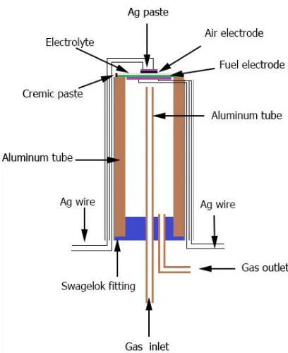
[image:3.596.193.397.499.749.2]
Fig. 1 shows the experimental setup for the SOEC electrolysis of fuel gas. Seal ceramic paste with cell before measuring, then the fuel electrode to reduce by hydrogen with the rate of 50 ml min-1 at 800 °C for 2 h, and the air electrode was exposed in the air. Conduct performance and electrochemical impedance measurements on the cell from 800 to 700 °C with 30, 50 and 70 vol.% steam in the N2 carrier
gas. The current density-voltage (I-V) curve and electrochemical impedance spectrum (EIS) were obtained using an Electrochemical Analyzer (CHI604E) in the frequency range of 0.1 Hz-100 kHz with voltage stage between 0.4 V and 1.5 V. The microstructure of the cell was characterized by field-emission scanning electron microscopy (FESEM, Quant 250 FEG).
3. RESULTS AND DISCUSSION
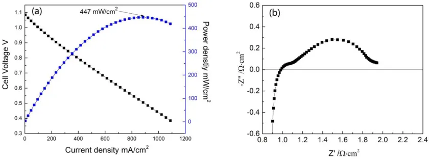
Fig. 2(a) shows the I-V-P curve of the cell with humidified H2 as the fuel and air as the oxidant
at 800 °C. The value of open circuit voltage is 1.09 V at 800 °C, which is very close to the theoretical value at this temperature, indicating that the electrolyte is well densification. The cell has a maximum power density of 447 mW cm-2 at a current density of 884 mA cm-2. In literature, Timurkutluk [22]
reported that the peak power densities at 800 °C are measured to be 483 mW cm-2 for cell with aqueous tape casting method for preparing fuel electrode-supported SOFCs. Fig. 2(b) shows the corresponding EIS curve of the cell at 800 °C. The high frequency intercept of the EIS curve reflects the ohmic impedance of the cell, and the low frequency intercept is the total impedance of the cell. The difference between the two represents the polarization impedance of the cell. In the open circuit voltage condition, the total impedance of the cell is 1.94 Ω cm2, and the ohmic impedance is 0.99 Ω cm2, so that the
polarization impedance of the cell is 0.95 Ω cm2. Wang [23] have reported their work with similarity
method for preparing cell. The open circuit voltage (OCV) of 1.08 V is close to the theoretical value at 800 °C. The total impedance resistance value is 0.79 Ω cm2 and the maximum power density is over 800 mW cm−2 at 800 °C. In comparison, the performance of SOFCs is lower than that of Wang study, because the ratio of NiO and YSZ of fuel electrode and air electrode materials is different. But this also indicates that excellent performance can be achieved by using aqueous tape casting.
[image:4.596.88.508.579.735.2]
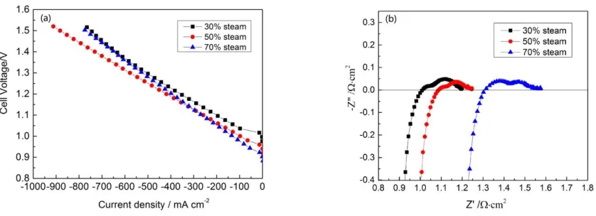
The raw material for hydrogen production by SOECs electrolysis is steam, and the supply flow of steam in the SOECs fuel electrode will significantly influence the cell electrolysis performance. Different steam contents with 30 vol.%, 50 vol.%, and 70 vol.% steam was set at 800 °C respectively. Fig. 3(a) shows the cell I-V of a fuel electrode at 800 °C under three different sets of steam content. The OCV of the cell at 30, 50 and 70 vol.% steam content are 0.98, 0.94 and 0.90 V, respectively. The increase of steam content in fuel electrode significantly reduces the open circuit voltage during electrolysis. Besides, with the increase of the steam content increase, the I-V curve is still in the linear region. Where, at the electrolytic voltage of 1.3 V, the electrolytic current of 50 vol.% steam is 630 mA cm-2, which is higher than 30 vol.% and 70 vol.%. The electrolytic current of 70 vol.% steam is 540 mA cm-2, similar study [24] the cell of NiO-YSZ fuel electrode supporter was prepared by dry pressing method, the electrolysis current is 500 mA cm-2 with 70vol.% steam in 800 °C. The electrolytic current of cell prepared by aqueous tape casting is higher than that of cell prepared by dry- pressing method at the same electrolytic voltage. Fig. 3(b) shows the impedance spectroscopy of cell measured in three different steam contents at 800 °C. The Ro values are 1.010, 1.085, and 1.250 Ω cm2 at 30 vol.% steam, 50 vol.% steam, and 70 vol.% steam, respectively. The Rp values are 0.204, 0.161, and 0.190 Ω cm2 at 30 vol.% steam, 50 vol.% steam, and 70 vol.% steam, respectively. As can be seen from the Rovalues, after the steam concentration increases from 30 vol.% to 70 vol.%, ohmic resistance of the cell also increases sharply. But for Rp values, the trend of polarization resistance is to decrease first and then increase, and the value of Rp is at least 0.161 Ω cm2 at 50 vol.% steam.
Figure 3. (a) The I-V curve and (b) EIS curve of the cell with different steam contents at 800 °C.
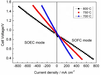
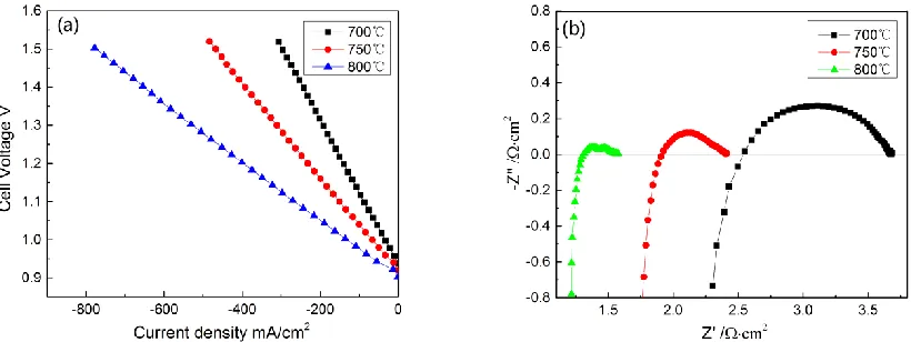
Fig. 4 shows the current-voltage (I-V) for a single cell tested at different temperatures with 70 vol.% steam, respectively 800, 750, and 700 °C. When the current density of cell is in the negative, the cell is in SOEC mode, and SOFC mode in the contrary. In SOEC mode, the current densities at a voltage of 1.3 V were -195, -300, and -530 mA cm-2 at temperatures of 700, 750, and 800 °C, respectively. In SOFC mode, the current densities at a voltage of 0.6 V were 187, 300, 440 mA cm-2 at temperatures of
[image:5.596.91.510.428.580.2][image:6.596.130.472.156.412.2]
at the same temperature, and the cell is in the dominant region of ohmic polarization.The performance improved with increasing temperature both in SOFC and SOEC modes. This was due to oxygen ions passed through the electrolyte, and electrochemical reactions on the electrodes were thermally activated.
Figure 4. The current-voltage of SOFC mode and SOEC mode at 700,750 and 800 °C.
[image:7.596.92.502.235.389.2]
resistance decreasing with increasing temperature implied that the process of oxygen ions transferring through oxygen vacancies in the electrolyte was thermally activated. The Rp values are 0.231, 0.482, and 1.151 Ω cm2 at 800 °C, 750 °C, and 700 °C, respectively. As the polarization resistance of the fuel electrode on the hydrogen fuel is generally small, the polarization resistance can only be attributed to the air electrode. Therefore, as the temperature increases, the oxygen reduction resistance on the air electrode decreases, indicating that the reaction on the air electrode is also thermally activated.From the I-V curves in Fig. 4, a very smooth transition between the SOFC and SOEC mode proves that the cell gets a good reversibility performance [26].
Figure 5. The I-V and EIS curves of the cell at 800, 750 and 700℃ with 70 vol.% steam.
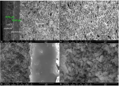
Figure 6. Cross-section images of the whole cell (a), the fuel electrode (b), the interface of air electrode and electrolyte (c) and the air electrode (d).
4. CONCLUSIONS
The cell was fabricated by aqueous-based co-tape casting in conjunction with a co-sintering process. The feasibility of the SOECs electrolysis of different steam contents and different temperatures was evaluated. Under SOFC mode, the maximum power density is 447 mW cm-2 at 800 °C with humidified H2 as the fuel and air as the oxidant. Under SOEC mode, the best electrolysis performance
was obtained when the steam content was 70% of the volume, and the hydrogen production rate of button cell is 222.2 ml h-1 cm-2. These results prove the feasibility of manufacturing the large area fuel electrode supported SOECs by aqueous-based co-tape casting, which make SOECs is more competitive in the hydrogen production industry.
ACKNOWLEDGMENTS
References
1. D. Honnery and P. Moriarty, International Journal of Hydrogen Energy, 36 (2011) 3283. 2. C. Corgnale, T. Motyka, S. Greenway, J.M. Perez-Berrios, A. Nakano, H. Ito and T. Maeda,
Journal of Alloys and Compounds, 580 (2013) S406.
3. R. Amirante, E. Cassone, E. Distaso and P. Tamburrano, Energy Conversion and Management, 132 (2017) 372.
4. T. Janoschka, N. Martin, U. Martin, C. Friebe, S. Morgenstern, H. Hiller, M.D. Hager and U.S. Schubert, Nature, 527 (2015) 78.
5. Z.H. Tan, L.Z. Ouyang, J.M. Huang, J.W. Liu, H. Wang, H.Y. Shao and M. Zhu, Journal of Alloys And Compounds, 770 (2019) 108.
6. B. Lee, J. Heo, S. Kim, C. Sung, C. Moon, S. Moon and H. Lim, Energy Conversion and Management, 162 (2018) 139.
7. M. Ni, M.K.H. Leung and D.Y.C. Leung, International Journal of Hydrogen Energy, 33 (2008) 2337.
8. M. Ni, M.K.H. Leung, K. Sumathy and D.Y.C. Leung, International Journal of Hydrogen Energy, 31 (2006) 1401.
9. J. Chi and H. Yu, Chinese Journal of Catalysis, 39 (2018) 390.
10.E. Ioannidou, C. Neofytidis, L. Sygellou and D.K. Niakolas, Applied Catalysis B: Environmental., 236 (2018) 253.
11.Q. Fang, L. Blum and N.H. Menzler, Journal of the Electrochemical Society, 162 (2015) F907. 12.S. Tonekabonimoghadam, R.K. Akikur, M.A. Hussain, S. Hajimolana, R. Saidur, H.W. Ping, M.H.
Chakrabarti, N.P. Brandon, P.V. Aravind, J.N.S. Nayagar and M.A. Hashim, Energy, 90 (2015) 1759.
13.J. Zhou, L. Zhang, C. Liu, J. Pu, Q. Liu, C. Zhang and S.H. Chan, International Journal of Hydrogen Energy, (2019) 21110.
14.J.W. Fergus, Solid State Ionics, 177 (2006) 1529.
15.Y.J. Kang, S.H. Jung, Y.T. An, B.H. Choi and M.J. Ji, Korean Journal of Metals And Materials, 53 (2015) 287.
16.J. Zhou, Q. Liu, L. Zhang, Z. Pan and S.H. Chan, Energy, 115 (2016) 149.
17.Z. Wang, J. Qian, J. Cao, S. Wang and T. Wen, Journal of Alloys And Compounds, 437 (2007) 264. 18.Q. Zhang, X. Luo, W. Li, H. Zhuang and D. Yan, Journal of Materials Science, 38 (2003) 1781. 19.S. Liu, F. Ye, S. Hu, H. Yang, Q. Liu and B. Zhang, Journal of Alloys And Compounds, 647 (2015)
686.
20.D.M. Amaya, D. Estrada, D. Hotza, J.B. Rodrigues Neto and J.A. Escobar, Journal of the European Ceramic Society, 37 (2017) 5233.
21.J. Zhou, Q. Liu, Q. Sun and S.H. Chan, Fuel Cells. 14 (2014) 667.
22.B. Timurkutluk, S. Celik and E. Ucar, Ceramics International, 45 (2019) 3192. 23.C. Wang, L. Luo, Y. Wu, B. Hou and L. Sun, Materials Letters, 65 (2011) 2251.
24.B. Yu, W. Zhang, J. Xu, J. Chen, X. Luo and K. Stephan, International Journal of Hydrogen Energy, 37 (2012) 12074.
25.G.-B. Jung, C.-T. Chang, C.-C. Yeh, X.-V. Nguyen, H. Chan, C.-Y. Lin, J.-W. Yu, W.-T. Lee, S.-W. Chang and I.C. Kao, International Journal of Hydrogen Energy, 41 (2016) 21802.
26.Y. Tian, J. Li, Y. Liu, J. Yang, B. Liu, L. Jia, J. Jiang, B. Chi, J. Pu and J. Li, International Journal of Hydrogen Energy, 43 (2018) 12603.