The Identification and Exploitation of Almost
Symmetries in Planning Problems
Julie Porteous, Derek Long and Maria Fox
Department of Computer and Information Sciences,
University of Strathclyde,
Glasgow, UK
{Julie.Porteous,Derek.Long,Maria.Fox}@cis.strath.ac.uk
Abstract
Previous work in symmetry detection for plan-ning has identified symmetries between domain objects and shown how the exploitation of this information can help reduce search at plan time. However these methods are unable to detect symmetries between objects that are al-most symmetrical: where the objects must start (or end) in slightly different configurations but for much of the plan their behaviour is equiv-alent. In the paper we outline a method for identifying such symmetries and discuss how this symmetry information can bepositively ex-ploitedto help direct search during planning We have implemented this method and integrated it with the FF-v2.3 planner and in the paper we present results of experiments with this ap-proach that demonstrate its potential.
1
Introduction
Symmetry can arise in a wide range of search problems, including CSPs [10], model-checking [9], automated rea-soning [1] and planning [3]. It has been shown (for exam-ple by Joslin & Roy 1997 [10] and Fox & Long 1999 [3]) that when such problems feature large-scale symmetric structure the detection and subsequent exploitation of that structure can dramatically reduce the size of the search space and consequent time taken to generate a solution
A symmetry is a function that maps the structure of a problem onto itself. In other words, a symmetry is an automorphism of the problem definition. In planning problems symmetry can arise from different sources, for example:
• Object functional equivalence [3]: where symmetry groups are formed between domain objects that can be substitute for one another in their functional roles within a plan. For example, in a logistics do-main which involves transporting packages between locations, the individual packages will be named and distinguished but for those that must start and end at the same location (with no distinguishing features
other than their names) then these objects are seen as being functionally equivalent.
• Object configuration [10]: where symmetry groups are formed between configurations of objects that are symmetric with one another (this can be seen as a generalisation of the single object functional equivalence).
• Plan permutation symmetry[4; 14]: where the sym-metry group is formed not between domain objects but between orderings of different plan actions. As an example, suppose that the plans hA;B;Ci and hB;A;Ci are equivalent. Then the automorphism that makes this symmetry is the mapping which swaps the actions A and B and hence they are seen as symmetrical.
In the work we report here we have focussed on the de-tection of object symmetries and in particular what we refer to asalmost symmetrybetween domain objects. We were motivated by the observation that for many plan-ning problems valuable object symmetry information is not identified by existing approaches because the domain objects arealmostsymmetrical. This phenomenon arises in many planning problems where groups of objects be-gin in slightly different configurations, or are required to reach slightly different configurations, but where the majority of their behaviour is essentially equivalent to the behaviour of the other objects in the group.
there is a high degree of symmetry in the body of the problem. We classify situations like this asalmost sym-metric because the objects in the domain can be made symmetric by applying an appropriate abstraction to the domain.
An approach proposed by Fox and Long [5] was to solve the abstracted problem and then to add a plan fragment to the beginning of the solution in order to account for the difference between the abstracted initial state and the real initial state. But we have taken a different approach and instead are interested in the local situation of each object in the initial and goal states and seek to abstract out any irrelevant information for that object. For example, suppose we have two crates
crateAandcrateB, both at the top of a stack of crates (these could be at the same or at different locations in the depot world). The local situation of the crates might be described as:
CrateA:clear(CrateA)andon(CrateA, ?) CrateB:clear(CrateB)andon(CrateB, ?)
and these crates are viewed as symmetrical because they are both at the top of (some) stack (we’ve used ? to rep-resent the crate that they are stacked on since we aren’t interested in its identity). Their initial state is different to the two crates on the bottom of each stack,CrateY
andCrateZ, which could be described as follows:
CrateY:on(?,CrateY)andon pallet(CrateY,?) CrateZ:on(?,CrateZ)andon pallet(CrateZ,?)
At the level of abstraction in which we ignore other infor-mation (in this case, the precise location of the crates on the pallets) we can seeCrateY andCrateZ as symmet-rical in so far as they are both on a pallet with another crate(s) on top. So these objects are seen as almost sym-metrical and we reason that we may well need to perform similar operations on these objects during the course of any eventual solution plan.
The remainder of the paper is organised as follows: in section 2 we describe a method for automatically identi-fying almost symmetries from planning problem descrip-tions and then in section 3 we look at how this infor-mation might be exploited in a target planning system. Section 4 discusses results of experiments carried out us-ing the symmetry information, and in section 5 we look at our goals for future work.
2
Identification of almost symmetries
Our starting point for identifying almost symmetries was the method used by Joslin and Roy [10]: for a given planning problem build a graph representing the object relationships present in the initial and goal states of the problem and then use NAUTY [12], the graph automor-phism discovery tool, to identify automorautomor-phisms in the graph. The key difference with our approach is the way in which the graph is constructed.
Figure 1 gives an outline algorithm that, given a plannning problem, identifies a subset of the almost symmetries of the domain. The algorithm constructs
1. Begin with the graphG, initially empty. The nodes ofGwill be coloured.
2. For each object in the domain, add a vertex to G. Two such verticesVxandVywill be the same colour
if they are the same type.
3. For each object in the domain, collect the set of predicates that it is contained in in the initial state of the problem, and add this set as a vertex to G. Two such verticesVxandVy are the same colour if
(a) the size of the set of predicates is the same (b) the predicates in the set have the same names
(c) the predicates have the same number and type of arguments
(d) the object of interest is in the same position in the argument (e.g. for object b1, on(b1, b2) is different toon(b3, b1))
(e) a vertex for a set of predicates never has the same colour as a vertex for a domain object 4. For each object in the domain, collect the set of
predicates that it is contained in in the goal state of the problem, and add this set as a vertex toG. Cri-teria for equality of two such vertices are the same as for point 3 above.
5. Once generated, give the graph G to NAUTY. It will return generators for the graphs automorphism group. We can then restrict the generators to those vertices representing domain objects and hence the result will be groups of symmetrical domain objects.
Figure 1: Identification of Almost Symmetries
a coloured graph which captures these almost symme-tries and then uses NAUTY to find the symmesymme-tries of the graph. The symmetries are restricted to domain ob-jects.
As an example, consider the simple blocks world prob-lem shown in figure 2. Firstly the graph will contain vertices corresponding to each of the domain objects:
vertex 0: b1
vertex 1: b2
vertex 2: b3
vertex 3: b4
vertex 4: b5
vertex 5: b6
Then the grouping of predicates for each domain ob-ject would lead to the following sets for the initial state (where the object name in brackets is the domain object of interest at this vertex):
vertex 11 (b6): {on(b5,b5),ontable(b6)} and the following sets for the goal state:
vertex 12 (b4): {clear(b4),on(b4,b5)} vertex 13 (b5): {on(b4,b5)}
vertex 14 (b6): {clear(b6),on(b6,b3)} vertex 15 (b3): {on(b6,b3)}
vertex 16 (b1): {clear(b2),on(b2,b1)} vertex 17 (b2): {on(b2,b1)}
So the corresponding graph which is input to NAUTY is as shown below (where Va : Vx, Vy, ..., Vz denotes edges
from vertexVa to verticesVx,Vy, ..., andVz.
0: 6, 17 1: 7, 16 2: 8, 15 3: 9, 12 4: 10, 13 5: 11, 14 6: 0 7: 1 8: 2 9: 3 10: 4 11: 5 12: 3 13: 4 14: 5 15: 2 16: 1 17: 0
Also input to NAUTY is the graph colouring information as follows (here the| delimits the different colours):
[0 : 5|6,8,10|7,9,11|12,14,16|13,15,17]
The output from NAUTY is the generators for the graphs automorphism group. When restricted to domain objects, the output for this problem is:
vertices 0, 2, 4 or{b1, b3, b5} vertices 1, 3, 5 or{b2, b4, b6}
and this almost symmetry is precisely what we would expect from the input problem. From figure 2 we can see that blocks 1, 3 and 5 will be moved from the (almost) identical position of being on top of a block to being on the bottom of a stack (or at least under some other block) and for blocks 2, 4 and 6 they will all be moved from being at the base of a stack of blocks to being at the top of the stack. This symmetry is said to be “almost” since they start and end in slightly different configurations but we would suppose that any solution plan will need to perform a similar set of operations on these groups of symmetric objects.
3
Exploitation of symmetry information
Using the approach discussed in section 2, we are able to automatically identify useful looking almost symmetries. In this section we will consider how best to exploit this information in order to improve the performance of a
Figure 2: Blocks: Example Problem
target planning system. There are a number of issues to consider here:
• whether to usenegative exploitationwhere the sym-metry information is used to prune branches of the search space; orpositive exploitationwhere the sym-metry information is used heuristically to decide on which areas of the search space to explore next. • the type of problem and whether it can be
classi-fied as low constrained or highly constrained. For low constrained problems, these problems may be-come large but they will never (or seldom) require backtracking because of the lack of constraints in the problem space. In such problems it is unlikely that negative exploitation of symmetry (ie pruning) could be of any help. On the other hand, for highly constrained problems where there is a high density of failure (ie bad choices) using symmetry informa-tion in a negative way is likely to be a very good strategy since it makes it less likely for the planner to repeat earlier bad choices.
• the type of planner that we are interested in: opti-mal planners such as Graphplan [2] are often forced to backtrack because they are searching for an opti-mal plan and for such a planner the most promising strategy would be to use symmetry information neg-atively to prune branches of the search space (this is the approach taken by Fox and Long [3]). But for non optimal planners, such as state space planners like FF [7] an approach that uses positive exploita-tion looks promising.
Based on this apparent “good fit” between positive ex-ploitation of symmetry information and non optimal planning we decided to investigate this combination in our experimental evaluation and the actual planning sys-tem that was chosen was ff-v2.3 [7; 6]. But we also iden-tified a relationship between the constrained-ness of the problem domain and the efficacy of positive exploitation and hence we will include a range of problem domains in the experiments to test this behaviour. Our hypothesis would be that positive exploitation would be less use-ful in highly constrained domains such as Freecell which feature dead ends and a high density of failure.
heuris-tic guide for selection between proposed action choices. During plan generation FF performs a forward state space search and at each stage proposes actions to ap-ply at the current state. We amend FF’s action selection strategy to favour actions that helped in earlier plans for symmetrical objects, in other words the heuristic is to :
... prefer actions that “involve” objects that are symmetrical to objects that have appeared in actions earlier in the plan ...
This is consistent with our earlier comments that if we know that objects are (almost) symmetrical in the con-text of a particular plan then we will have to perform a similar set of operations on them.
This heuristic is straightforward to implement in FF. At each stage during plan generation we have a current plan which consists of the actions applied so far to get from the initial state to the current state. At this stage a set of possible next actions are proposed by FF. We can bypass its usual action selection strategy by favouring those which feature objects that are symmetrical to any that have appeared in actions in the plan so far. For each action we can simply keep a count of the number of symmetrical objects, breaking any ties by using FF’s standard action selection strategy.
To illustrate the use of the symmetry information in ff-v2.3, consider a Depots problem (pfile3 in the IPC3 test set) where the following objects are found to be symmet-ric:
{pallet1, pallet2} {crate4, crate5} {hoist0, hoist1}
and at some intermediate point during plan generation the plan so far will be:
hdrive(truck1,distributor0,depot0),
drive(truck1,depot0,distributor1),
drive(truck0,depot0,distributor1),
lift(hoist2,crate5,crate2,distributor1),
load(hoist2,crate5,truck1,distributor1)i Here the set of actions proposed by FF are:
drive(truck1,depot0,distributor0) drive(truck1,depot0,distributor1) drop(hoist2,crate2,pallet2,distributor1) lift(hoist0,crate1,pallet0,depot0) lift(hoist1,crate4,crate3,distributor0)
and the highest rated symmetrical action, and hence the action selected for application next, is
lift(hoist1,crate4,crate3,distributor0)
because the action appears in the plan so far and also it contains an object that is symmetrical with another object in that action (crate4). So it can be seen that our strategy is forcing the planner to commit earlier to ac-tions that have proved successful earlier for symmetrical objects (ie we needed to lift upcrate5 and it may be a good idea to do the same thing withcrate4).
We tested this strategy in a series of experiments (see section 4) and the results are promising. But there are more sophisticated ways of using this information and we return to discussion of this in section 5.
4
Experimental Results
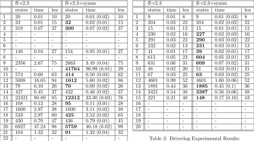
In this section we include results of some experiments that compare the performance of the planner ff-v2.3 [7; 6] with a version of the same planner that uses symmetry information as a positive heuristic in deciding which ac-tion to apply next. We’ll call this plannerff-v2.3+symm. For the domains: depots, driverlog, freecell and rovers these problem sets are from the IPC3 [11] domains repos-itory and the numbers down the left hand side of the ta-bles are the problem numbers. We also included results for some randomly generated gripper problems and here the left hand column of the table, B-G, gives the number of balls and the number of grippers respectively. For each planner we have included the number of states expanded, the overall CPU time taken to generate a solution and the length of the plan. We used a 100 second time cut-off for CPU time and use a - to show that the planner failed to solve the problem within that time limit. For
ff-v2.3+symm, in the time column, we have included in brackets the time taken for the symmetry pre-processing. Table 1 shows the results for the Depots domain. We observe that in about half of the problem instances ff-v2.3+symm expands fewer states to find a solution to the problem. But the behaviour is most interesting in those problems which appear to be harder for ff-v2.3
(for example problems 10, 12, 15 and 20). For these problems, both the number of states expanded and the overall CPU time is greatly reduced with the use of sym-metry information. It can also be seen that the time for pre-processing the symmetry information remains con-sistently low across the set of problems.
The results for the Driverlog domain (see table 2) show a slightly different picture. For most of the problems thatff-v2.3+symmmanaged to solve there was a reduc-tion in the number of states that were expanded but in most cases the reduction was slight and was certainly not sufficient to improve the overall time taken to solve the problem instance. How can we explain this? Is it the case that there is little opportunity to exploit symmetry in this domain? In this domain the idea of looking at the local characteristics of each object fails to yield much useful information. For example, for pfile9 the locations of the packages (package1, ..., package6) are initially
at(package1,s2) at(package2,s1) at(package3,s3) at(package4,s0) at(package5,s1) at(package6,s1)
and the local properties of these objects in the goal is:
ff-v2.3 ff-v2.3+symm
states time len states time len 1 20 0.01 10 20 0.01 (0.02) 10 2 33 0.01 15 32 0.02 (0.01) 15 3 318 0.07 37 300 0.07 (0.02) 37
4 - - -
-5 - - -
-6 - - -
-7 148 0.04 27 154 0.05 (0.01) 27
8 - - -
-9 2356 2.67 75 2663 3.49 (0.04) 75 10 - - - 41764 96.99 (0.01) 29 11 574 0.60 63 414 0.50 (0.03) 62 12 5008 16.65 94 1612 5.60 (0.02) 86 13 79 0.10 26 70 0.09 (0.02) 26 14 427 0.45 37 432 0.46 (0.02) 37 15 22421 80.89 85 12312 33.30 (0.03) 76 16 108 0.12 28 95 0.11 (0.01) 28 17 1600 2.97 38 1600 3.11 (0.02) 38 18 533 2.97 60 425 2.52 (0.02) 65 19 430 0.70 47 436 0.79 (0.01) 45 20 6927 47.24 98 5759 40.18 (0.02) 99 21 104 1.32 32 91 1.32 (0.04) 32
22 - - -
-Table 1: Depots Experimental Results
at(package3,s1) at(package4,s0) at(package5,s1) at(package6,s1)
and all 6 packages are found to be symmetrical. But this tells us little and here the abstraction works against us since for this domain/problem the actual location of each of the packages is important. For this reason we combined our analysis with an implementation of the approach from [10] and this did help us discriminate some more useful symmetry groups. For example for this problem the object configuration approach enabled us to further identifypackage5andpackage6as symmet-rical (in fact they both stay in the same location for initial state and goal). So from these results the overall picture is that the symmetry analysis yields little gain in this domain.
The potential of using almost symmetry is shown in the results for the Freecell domain shown in table 3. Here, there is a reduction in the number of states ex-panded in most of the instances that are solved by ff-v2.3+symm (and this manages to solve 1 more instance than the base planner). And for some instances (see for example, problems 9, 10, 13, 15 and 17) the reduction is quite dramatic both in terms of the number of states and the overall time taken to generate the solution (including time taken to identify symmetries which remains consis-tently low). This is what we would expect since this domain features the sort of local almost symmetry that we are interested in: for example for cards that are in
ff-v2.3 ff-v2.3+symm
states time len states time len 1 9 0.01 8 9 0.01 (0.03) 8 2 204 0.03 22 204 0.02 (0.02) 22 3 15 0.01 12 15 0.01 (0.01) 12 4 230 0.02 16 227 0.02 (0.03) 16 5 291 0.03 22 290 0.03 (0.02) 22 6 232 0.02 13 231 0.03 (0.01) 13 7 41 0.01 17 39 0.02 (0.01) 17 8 615 0.05 23 604 0.05 (0.01) 23 9 631 0.06 31 609 0.07 (0.02) 31 10 48 0.02 20 51 0.03 (0.01) 21 11 67 0.03 25 63 0.03 (0.02) 25 12 4601 0.99 52 4601 1.00 (0.06) 52 13 1891 0.44 36 1885 0.45 (0.1) 36 14 3421 0.54 38 3387 0.56 (0.06) 38 15 221 0.21 48 148 0.17 (0.10) 43
16 - - -
-17 - - -
-18 - - -
-19 - - -
-20 - - -
-Table 2: Driverlog Experimental Results
the middle of a column (e.g. in the midst of a stack) we will have to do a similar series of things to get it to its home position.
However, in some instances the use of the symme-try information can seriously degrade performance (e.g. problems 7, 8, 14 and 16). How can we explain this be-haviour? This may be because this problem domain is quite a highly constrained domain and it may indicate that in some cases the positive exploitation fails to avoid bad choices that could lead to dead ends.
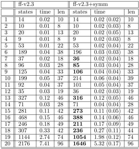
The picture from the results in the Rovers domain (ta-ble 4) is very encouraging. Here there is an improvement in the number of states expanded in half of the instances and this improvement becomes more marked as the prob-lem instances increase in size. Also, encouraging is the observation that the use of symmetries doesn’t degrade performance in the problem instances from the IPC3 test set.
[image:5.595.54.554.53.330.2]ff-v2.3 ff-v2.3+symm
states time len states time len 1 33 0.03 9 26 0.03 (0.05) 9 2 24 0.05 17 22 0.04 (0.06) 17 3 40 0.07 23 38 0.07 (0.06) 22 4 88 0.14 33 61 0.11 (0.06) 31 5 80 0.26 35 123 0.36 (0.06) 44 6 121 0.62 39 80 0.40 (0.07) 37 7 220 1.01 57 486 1.86 (0.07) 46 8 146 1.14 59 318 2.22 (0.07) 60 9 431 2.75 49 160 1.17 (0.06) 61 10 237 2.51 61 80 0.97 (0.08) 51 11 613 6.37 82 589 6.21 (0.09) 81 12 97 1.00 52 98 1.10 (0.08) 52 13 - - - 964 15.88 (0.09) 68 14 473 7.05 69 718 11.95 (0.11) 69 15 3866 73.29 76 859 18.97 (0.08) 89 16 271 5.07 71 602 13.07 (0.11) 73 17 352 9.51 81 169 4.58 (0.11) 75
18 - - -
-19 - - -
-20 - - -
-Table 3: Freecell Experimental Results
ff-v2.3 ff-v2.3+symm
[image:6.595.313.573.50.216.2]states time len states time len 1 14 0.02 10 14 0.02 (0.02) 10 2 10 0.01 8 10 0.02 (0.03) 8 3 20 0.01 13 20 0.02 (0.05) 13 4 9 0.01 8 9 0.02 (0.03) 8 5 53 0.01 22 53 0.02 (0.04) 22 6 189 0.04 38 196 0.03 (0.03) 38 7 37 0.02 18 36 0.02 (0.04) 18 8 96 0.03 28 85 0.03 (0.04) 28 9 125 0.04 33 106 0.04 (0.04) 33 10 199 0.05 37 214 0.06 (0.04) 39 11 92 0.04 37 101 0.05 (0.04) 37 12 35 0.03 19 36 0.02 (0.03) 19 13 327 0.12 46 316 0.12 (0.05) 46 14 71 0.03 28 71 0.04 (0.04) 28 15 281 0.11 42 273 0.11 (0.05) 42 16 468 0.15 46 388 0.14 (0.06) 46 17 246 0.18 49 211 0.17 (0.09) 49 18 307 0.33 42 236 0.27 (0.11) 44 19 1144 2.74 74 1054 1.98 (0.12) 74 20 2176 7.41 96 1646 5.32 (0.17) 96
Table 4: Rovers Experimental Results
ff-v2.3 ff-v2.3+symm
states time len states time len 50-50 152 1.85 101 104 1.01 101
(0.28) 50-100 152 4.19 101 104 2.29 101
(0.73) 100-50 352 10.22 203 207 5.20 203
(0.91) 100-100 302 15.95 201 204 8.09 201
(1.81) 100-150 302 28.35 201 204 15.42 201
(3.20)
200-200 - - - 404 66.78 401
[image:6.595.51.304.71.332.2](14.27)
Table 5: Gripper Experimental Results
5
Conclusions and Future Work
In the paper we have introduced a method for extract-ing almost symmetries from an input plannextract-ing problem, discussed how this information could be exploited in a target planner and discussed the results of experiments on the implemented system. The results (see section 4) show the potential of this approach: the use of symmetry information as a positive heuristic to select next action application can make a significant reduction on the num-ber of states expanded during search and also the overall time taken to generate a solution plan.
These promising results make us keen to further de-velop this work and the first part of that is to carry out a more extensive set of experimental tests to try and build up a clearer picture of the effect of the pos-itive exploitation of almost symmetry information. In addition we are keen to further develop the way that the symmetry information is exploited by the target planning system. An important feature of (almost) symmetry is that it is dynamic and changes during the course of a plan so a group of domain objects may be (almost) symmetric during early stages of the plan and then this changes and they become symmet-ric with other objects during later and final stages of the plan. The idea is to use landmarks analysis [13; 8] to decompose a planning problem into sub-problems and then to identify (almost) symmetrical objects for each decomposed part of the problem. It is anticipated that this will both increase the amount of symmetry in-formation that is detected and also the impact that this makes on planner performance.
References
[1] G. Audemard and B. Benhamou. Reasoning by Symmetry and Function ordering in Finite Model Generation. InProceedings of the 18th International Conference on Automated Deduction, 2002.
[image:6.595.52.294.402.661.2]Inter-national Joint Conference on Artificial Intelligence (IJCAI), 1995.
[3] M. Fox and D. Long. The Detection and Exploita-tion of Symmetry in Planning. In Proceedings of the 16th International Joint Conference on Artifi-cial Intelligence (IJCAI), 1999.
[4] M. Fox and D. Long. Plan Permutation Symmetries as a source of Planner Inefficiency. InProceedings of the ?? Workshop of the UK Planning and Schedul-ing Special Interest Group (PLANSIG), 2003. [5] M. Fox and D. Long. Symmetries in Planning
Prob-lems. InProceedings of SymCon, 2003.
[6] J. Hoffmann. The FF-v2.3 planner is avail-able to download from http://www.informatik.uni-freiburg.de/∼hoffmann/ff.html.
[7] J. Hoffmann and B. Nebel. The FF Planning Sys-tem: Fast plan generation through heuristic search.
Journal of Artificial Intelligence Research (JAIR), 2001.
[8] J. Hoffmann, J. Porteous, and L. Sebastia. Ordered Landmarks in Planning. To appear in: Journal of Artificial Intelligence Research (JAIR), 2004. [9] C. N. Ip and D. L. Dill. Better Verification through
Symmetry. Formal Methods in System Design, 9, 2001.
[10] D. Joslin and A. Roy. Exploiting symmetry in lifted CSPs. InProceedings of the 14th National Confer-ence on Artificial IntelligConfer-ence (AAAI), 1997. [11] D. Long and M. Fox (chairs). The Third
In-ternational Planning Competition (IPC3), 2002. http://planning.cis.strath.ac.uk/competition/. [12] B. McKay.NautyUsers Guide 1.5. Technical Report
TR-CS-90-02, Australian National University, 1990. [13] J. Porteous, L. Sebastia, and J. Hoffmann. On the Extraction, Ordering and Usage of Landmarks in Planning. InProceedings of the 6th European Con-ference on Planning (ECP), 2001.