City, University of London Institutional Repository
Citation
:
Ul Asad, H., Jones, K. and Surre, F. (2014). Verifying Robust Frequency Domain
Properties of Non Linear Oscillators using SMT. In: Pleskacz, W., Renovell, M., Kasprowicz,
D., Sekanina, L. and Bernard, S. (Eds.), 17th International Symposium on Design and
Diagnostics of Electronic Circuits & Systems. (pp. 306-309). IEEE. ISBN 978-1-4799-4560-3
This is the accepted version of the paper.
This version of the publication may differ from the final published
version.
Permanent repository link:
http://openaccess.city.ac.uk/12326/
Link to published version
:
http://dx.doi.org/10.1109/DDECS.2014.6868816
Copyright and reuse:
City Research Online aims to make research
outputs of City, University of London available to a wider audience.
Copyright and Moral Rights remain with the author(s) and/or copyright
holders. URLs from City Research Online may be freely distributed and
linked to.
Verifying Robust Frequency Domain Properties of
Non Linear Oscillators using SMT
Hafiz ul Asad
City University London EC1 0HB London,UK Email: [email protected]
Kevin D. Jones
City University London EC1 0HB London,UK Email: [email protected]
Frederic Surre
City University London EC1 0HB London,UK Email: [email protected]
Abstract—We present a novel mixed time and frequency do-main approach to the formal verification of oscillators properties which are specified in the frequency domain. We use robust periodogram specification to specify the oscillator behaviour in the close vicinity of the limit cycle. Using SAT modulo ODE (SMO) for Bounded Model Checking (BMC) of the non-linear hybrid automata, we show that the oscillator hybrid timed traces satisfy frequency domain specifications.
I. INTRODUCTION
Significant time is spent, in the industry, verifying analog and mixed signal (AMS) circuits using SPICE simulations. Formal methods have been successfully used to verify digital circuits and could provide better solutions for more reliable, less time consuming AMS circuits design too.
This paper describes the formal verification of the frequency domain properties of a non-linear oscillator when it operates in the close proximity of its limit cycle. We propose a mixed time and frequency domain approach for this purpose, and show that the hybrid timed traces of an oscillator, robustly belongs to the frequency domain power spectral envelop specified as con-straints on periodogram at harmonic frequencies. We model an oscillator circuit by the non-linear hybrid automaton and use the recent SMO technique for BMC of hybrid automata [1],[2], to compute the periodic invariant set (Limit Cycle). This limit cycle is verified against the robust frequency domain properties specification represented as constraints on its periodogram [3] at frequencies of interest.
A survey of the recent formal Analog and Mixed Signal (AMS) verification approaches can be found in [4]. Frequency domain approaches have been limited to the small signal AC analysis of a more approximate linearized model around an equilibrium point [5],[6].
II. PRELIMINARIES
A. Non-linear Dynamical Systems as Hybrid Automata
Definition 1 (Non-linear Hybrid Automata).
A Non-linear Hybrid Automata [7] is a tuple, H=(Loc, Var, Flow, Inv, Trans) where,
• Loc is a finite set of locations.
• Var is a set of continuous variables, Var={x1, x2...xn} ⊂Rn.
• Flow is the set of vector fields, i.e. Flow(`) is an autonomous subsystem for each ` ∈ Loc and is of the form,
˙
x = f`(x, u) (1)
f` : Dn` × Um 7→ D`n is a non-linear but at least
locally Lipschitz function of continuous vectorx∈Dn `,
and a non deterministic vector u ∈ Um of inputs and
parameters.
• Inv is a constraint on the domain Dn
` of each location
`∈ Loc,
Inv(`) = I`(x(t), u)≥0 (2)
• Trans is a set of discrete transitions; Each transition τ ∈ Trans, is a tuple τ = (`, guardτ, rτ, `0); where
(`,`0) ∈ Loc are the pre and post modes respectively, andguardτ is a switching conditions given by system of
equations,
guardτ = Gτ(x(t), u) = 0 (3)
here (guardτ ⊂ Dn`) ∈ G, G being the set of guards.
When a guard condition is met, a discrete transition takes place. rτ ∈ Ris a reset, where for each τ∈Trans, it is
a relation between elements of guardτ and elements of
Dn
`0, i.e.,rτ⊂guardτ×D`n0. HereRis the set of resets. We useD=S
`D n `.
B. Non-linear Hybrid Automata Verification Using SAT mod-ulo ODE
Andreas et al. in [1], presented SMO technique for the non-linear hybrid automata verification. Essentially, it is a technique based on the BMC of the non-linear hybrid au-tomata, encoded as a large number of constraints; involving boolean, linear and non-linear algebraic, and non-linear ODE constraints. Establishing reachability of a target region (inter-val), predicative encoding of the hybrid transition system is used, i.e.,
Φ = DECL[0]∧..∧DECL[N]∧Init[0]∧T rans[0,1]∧ ..∧T rans[(N−1), N]∧T arget[N].
step, Init[0] is the predicate for initial conditions at the 0-th step, T rans(N, N −1) is the transition relation between variables during N-th and (N-1)th step, andT arget[N]is the instantiation of the target predicate at the N-th step.
C. Limit Cycles in Hybrid Systems
Here we introduce concepts of the limit sets, periodic orbits, and the limit cycles in hybrid automata. We define a map
ΦH : R×D 7→ D, which describes piecewise smooth flow
over the hybrid domain D.
Definition 2 (Hybrid Limit Sets).
A pointz ∈Dis called anω-limit point ofy ∈Dif there is a sequence tn → ∞ for which,limn→∞ΦH(tn, y) =z. The
set of all such points ofz, is the hybridω-limit set LH ω(y).
Definition 3 (Hybrid periodic Orbits).
An orbit η is a closed periodic orbit if, for some x∈η, it is not an equilibrium (i.e. ΦH(t, x) 6= x), and ΦH(T, x) = x,
for some smallest T 6= 0.T is called the fundamental period of η. Ifη belongs to multiple domains D`, then it is called a
hybrid periodic orbit.
Definition 4 (Hybrid Limit cycle).
A closed hybrid orbit η, is called a hybrid limit cycle if,η⊂ LH
ω(y)for somey /∈η.
III. FREQUENCYDOMAINPROPERTIESSPECIFICATION OF HYBRIDLIMITCYCLE
This section introduces robust frequency domain properties specification of the hybrid limit cycle using periodogram based power spectral envelop.
A. Robust Specification of a Periodic Function in Frequency Domain
A scalar function g is periodic with period T if g(t) =
g(t +nT),∀t ∈ R and ∀n ∈ Z. We denote by P, the
set of all functions, which apart from being T periodic, also have the property of square sumability over a period T, i.e., P ⊂ L2[0, T]. All such periodic functions g(t) ∈ P can be represented by the sum of an infinite number of T-periodic sinusoids as,
g(t) =
∞
X
k=0
(akcosωkt+bksinωkt) (4)
where ωk = 2πk/T,ak, bk ∈R. Instead of an infinite series
representation of the periodic functions, we use notion of the almost periodic functions [8], which are represented by at most a countable number of sinusoids. We denote such set of almost periodic functions by AP, and thereforeg(t)∈ P is represented by its approximation Sk(t)∈AP,
SK(t) =
X
ωk∈ΩK
(akcosωkt+bksinωkt) (5)
where ΩK is the set of K frequencies. The finite series
representationSK(t)is the best approximation ofg(t), and it
has a least mean square error property. LetεK =maxkg(t)−
SK(t)krepresent the maximum approximation error, theng(t)
can be conservatively represented by SK(t)−εK ≤g(t) ≤
SK(t) +εK. The set F of all pairs {(a0, b0), ...(ak, bk)},
of the Fourier coefficients is called the frequency domain representation of a periodic functiong(t). Instead of specifying a periodic function g(t) in the frequency domain in terms of the set F, we use the periodogram specification which is defined below.
Definition 5 (Periodogram).
The energy content of a signal at each frequencyωk is called
a periodogram, and is given by,pk = (a2k+b
2
k). We denote by
P ={p0, ...pK}, the set of all periodograms at frequencies
ωk ∈ΩK.
To cater for parameter variations, temperature and uncer-tainty in initial conditions, we introduce the idea of robust periodogram specification.
Definition 6 (Robustness of Periodogram).
We specify P such that pairs of the Fourier series coef-ficients (ak, bk) for all ωk ∈ ΩK, result in the function
SK(t) (Eq. 5), which is the approximate representation of
the periodic functiong(t)and satisfy the inequality constraint SK(t)−εK ≤g(t)≤SK(t) +εK. We say that p0k ∈P has
k degree of robustness, if it can tolerate an k amount of
perturbation such that,∃pk ∈P :{pk−k≤p
0
k≤pk+k}.
B. Encoding Membership of the Limit Cycle in the Robust Power Spectral Envelop
Let η is a vector of scalar valued functions of time, η(t) := {η1(t), ..., ηn(t)} : R 7→ D. In other words,
η(t) = ΦHt (x);∀x ∈ η, i.e., η(t) represent the information about the hybrid limit cycle η at each time t. We define a power spectral envelopH(ωk) : ΩK 7→R+, which maps each
discrete frequency ωk ∈ ΩK to a periodogram pk. The set
APk of all almost periodic functions belongs to the power spectral envelop H(ωk) with k degree of robustness, if the
Fourier series coefficients satisfy the following constraints [9],
• ∀k∈N, (ωk> ωK) =⇒pk= 0,
• ∀k ∈ N, H(ωk)−k ≤ pk ≤ H(ωk) +k, such that
0≤ωk≤ωK.
We require that for each Sn,K(t) ∈ cl(APk), the scalar periodic orbitηn(t)satisfies the constraintSn,K(t)−εn,K ≤
ηn(t) ≤Sn,K(t) +εn,K. Here cl(APk) denotes closure of APk. We encode this by introducing the following set of constraints for the vectorη(t),
ψ1=
N ^ n=1 K ^ k=0
(Hn(ωk)−n,k≤pn,k≤Hn(ωk) +n,k)
,
ψ2=
N ^ n=1
∀t∈[tmin, tmax]
Sn,K(t) = K
X
k=0
(an,kcosωkt+bn,ksinωkt)
ψ3=
N
^
n=1
∀t∈[tmin, tmax]
Sn,K(t)−εn,K ≤ηn(t)≤Sn,K(t) +εn,K
.
Here the first constraint ψ1 puts upper and lower bounds on the periodograms at K frequencies in the presence of n,k perturbation forN scalar periodic functions. The second
constraint ψ2 ensures that for all time t all the N periodic variables are approximated byKsinusoids. The last constraint ψ3 conservatively over-approximate the periodic functionηn
taking in to consideration the error generated by the almost approximate periodic function Sn,K. The universal
quantifi-cations in the last two constraints are implicit, i.e. the BMC algorithm using SAT modulo ODE verify, whether there is any time instant t, at which any of these constraints are violated.
C. Membership as BMC Target Predicate
We determine the membership of the hybrid timed traces in the robust power spectral envelop by incorporating the additional set of constraints ψ1, ψ2, , ψ3, in the BMC algorithm discussed in section II.B. The initial conditions to the BMC is given in the form of a box Binitial (Considering
two dimensional system). Apart from the BMC ODE constraints, we add the set of constraints ψ1, ψ2, , ψ3, for each scalar variablexn to the BMC algorithm. In the ‘Target’
of the BMC algorithm, we introduce the following predicate, i.e.,
¬(time >0∧time <=tmax∧xn∈Binitial)∨
¬(kηn(t)−xn(t)k ≤σ)
This target predicate is actually a disjunction of two predicates. The predicate¬(time >0∧time <=tmax∧xn∈Binitial),
ensures that starting in the box Binitial, the trajectories
would return back to the same box before the maximum time limit is elapsed. A satisfiable valuation of this predicate is a counterexample of the periodicity property. The second predicate ¬(kηn(t)−xn(t)k ≤ σ), ensures that for all the
time, the distance of the hybrid timed traces from the possible time domain periodic trajectories obtained from the frequency domain specification, must be less than a user defined error. A satisfiable valuation of this predicate indicates the violation of the frequency domain specification implicitly.
IV. EXPERIMENTALEVALUATION
A. Evaluation Methodology
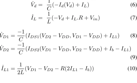
We have used Tunnel diode Oscillator (TDO) and Voltage Controlled Oscillator (VCO) benchmarks for the evaluation of our proposed methodology Figs. 1, that have been taken from [10],[11]. Equations Eq. 6, and Eq. 7, represent the non-linear ODE model of the TDO, whereId(Vd)is the non-linear model
of the tunnel diode. Mathematical model of VCO is given in Eqs. 8, 9, 10, where IDS(VGS, VDS) is the
[image:4.612.337.549.65.146.2]Schichman-Hodges PMOS model [11]. For TDO we have used parameters, C = 1nF±2%,L= 1mH±2%,R = 0.2Ohm and Vin∈
Figure 1:Oscillators Circuit Diagrams,Left:TDO,Right:VCO
Vd Below 0.055
Vd Between 0.055-0.35
Vd Above 0.35
V d≥0.055
V d≤0.055
V d≤0.35 V d≥0.35
Lin1/Cut2
Lin1/Sat2 Sat1/Sat2 Sat1/Lin2
Cut1/Lin2
Figure 2:Hybrid Automaton,Left:TDO,Right:VCO
[0.35,0.36]. Similarly, for VCO we have set,C= 3.43nF±
2%, L= 2.85mH±2%, Vctr= 0 andVDD∈[1.8,1.85]. We
have used the SMO solver iSAT-ODE [1], to exercise BMC formulations of the non-linear hybrid automata, and Matlab [12] to compute periodogram specifications. We have used a 2.6 GHZ Intel(R) Core(TM) i5 machine with 4 GB of memory for all the experiments.
˙
Vd=
1
C(−Id(Vd) +IL) (6)
˙
IL=
1
L(−Vd+IL.R+Vin) (7)
˙
VD1= −1
C (IDS1(VD2−VDD, VD1−VDD) +IL1) (8)
˙
VD2= −1
C (IDS2(VD1−VDD, VD2−VDD) +Ib−IL1) (9)
˙
IL1=
1
2L(VD1−VD2−R(2IL1−Ib)) (10)
B. Results
[image:4.612.323.563.347.493.2]Based on the non-linear diode and PMOS models in [10],[11], we got the non-linear hybrid automatons of TDO and VCO Fig. 2. Simulation traces are shown in Fig. 3a, Fig. 3b, whereas periodogram specifications for these traces are in Fig. 4a,. 4b, for TDO and VCO respectively. Here we have only shown specification for the fundamental frequency of the variables (Vd for TDO, and V D1 for VCO). The
upper and lower bounds on these periodograms have been found based on the designer judgement, i.e., we chose random values in the parameter spaces and correspondingly varied the “ power spectral envelop" and arrived at these bounds. Taking Vd ∈ [0.55,0.58], IL = 0.0 as the initial conditions
for the state variables, we model checked the TDO hybrid automaton for eight unwindings of the BMC formula Tab. IIa. Similarly for VCO, we considered initial conditions V D1 ∈
[−1.5,−1.4]volts, V D2 ∈ [−0.9,−0.8]volts, IL = 0.06mA
(a)TDO Limit Cycle Simulation (b)VCO Limit Cycle Simulation
Figure 3:Simulation Traces of Hybrid Automata
[image:5.612.110.500.328.450.2](a)TDO Robust Periodogram Specification (b)VCO Robust Periodogram Specification
Figure 4:Frequency Domain Properties Specifications
Depth Decision Time(Seconds) 0 Unsatisfiable 0 1 Unsatisfiable 81.07 2 Unsatisfiable 83.22 3 Unsatisfiable 304.37 4 Unsatisfiable 352.44 5 Unsatisfiable 1299.64 6 Unsatisfiable 1448.71 7 Unsatisfiable 26779.75 8 Unsatisfiable 27096.21
(a)TDO Verification Results
Depth Decision Time(Seconds) 0 Unsatisfiable 0 1 Unsatisfiable 6.13 2 Unsatisfiable 206.45 3 Unsatisfiable 538.39 4 Unsatisfiable 947.10 5 Unsatisfiable 2237.89 6 Unsatisfiable 3457.43 7 Unsatisfiable 11672.11 8 Unsatisfiable 15892.13
(b)VCO Verification Results
Table I:Experimental Results.
V. CONCLUSION
In this paper we have presented a novel mixed time and frequency domain approach to verify frequency domain prop-erties of oscillators when they operate in the close vicinity of the limit cycle.
REFERENCES
[1] Andreas Eggers, Martin Fränzle, and Christian Herde. Sat modulo ode: A direct sat approach to hybrid systems. InAutomated Technology for
Verification and Analysis, pages 171–185. Springer, 2008.
[2] Sicun Gao, Soonho Kong, and Edmund M Clarke. Satisfiability modulo odes. InFormal Methods in Computer-Aided Design (FMCAD), 2013, pages 105–112. IEEE, 2013.
[3] Michail Vlachos, Philip Yu, and Vittorio Castelli. On periodicity detection and structural periodic similarity. In SIAM International
Conference on Data Mining, pages 449–460, 2005.
[4] Mohamed H Zaki, Sofiène Tahar, and Guy Bois. Formal verification of analog and mixed signal designs: A survey. Microelectronics Journal, 39(12):1395–1404, 2008.
[5] Lars Hedrich and Erich Barke. A formal approach to verification of linear analog circuits wth parameter tolerances. InProceedings of the
conference on Design, automation and test in Europe, pages 649–655.
IEEE Computer Society, 1998.
[6] William Denman, Behzad Akbarpour, Sofiene Tahar, Mohamed H Zaki, and Lawrence C Paulson. Formal verification of analog designs using metitarski. In Formal Methods in Computer-Aided Design, 2009.
FMCAD 2009, pages 93–100. IEEE, 2009.
[7] Rajeev Alur, Costas Courcoubetis, Nicolas Halbwachs, Thomas A Hen-zinger, P-H Ho, Xavier Nicollin, Alfredo Olivero, Joseph Sifakis, and Sergio Yovine. The algorithmic analysis of hybrid systems.Theoretical
computer science, 138(1):3–34, 1995.
[8] Kenneth S Kundert and Alberto Sangiovanni-Vincentelli. Finding the steady-state response of analog and microwave circuits. In Custom
Integrated Circuits Conference, 1988., Proceedings of the IEEE 1988,
pages 6–1. IEEE, 1988.
[9] Aleksandar Chakarov, Sriram Sankaranarayanan, and Georgios Fainekos. Combining time and frequency domain specifications for periodic signals. In Runtime Verification, pages 294–309. Springer, 2012.
[10] Goran Frehse, Bruce H Krogh, Rob A Rutenbar, and Oded Maler. Time domain verification of oscillator circuit properties. Electronic Notes in
Theoretical Computer Science, 153(3):9–22, 2006.
[11] Goran Frehse, Bruce H Krogh, and Rob A Rutenbar. Verifying analog oscillator circuits using forward/backward abstraction refinement. In
Proceedings of the conference on Design, automation and test in
Europe: Proceedings, pages 257–262. European Design and Automation
Association, 2006.
[image:5.612.331.496.328.447.2]