Statistical Multi-Criteria Evaluation of Non-Nuclear
Asteroid Deflection Methods
Nicolas Thiry, Massimiliano Vasile
Aerospace Centre of Excellence, Department of Mechanical & Aerospace Engineering, University of Strathclyde
Abstract
In this paper we assess and compare the effectiveness of four classes of non-nuclear asteroid deflection methods applied to a wide range of virtual col-lision scenarios. We consider the kinetic impactor, laser ablation, the ion beaming technique and two variants of the gravity tractor. A simple but realistic model of each deflection method was integrated within a systematic approach to size the spacecraft and predict the achievable deflection for a given mission and a given maximum mass at launch. A sample of 100 syn-thetic asteroids was then created from the current distribution of NEAs and global optimisation methods were used to identify the optimal solution in each case according to two criteria: the minimum duration between the de-parture date and the time of virtual impact required to deflect the NEA by more than two Earth radii and the maximum miss-distance achieved within a total duration of 10 years. Our results provide an interesting insight into the range of applicability of individual deflection methods and argue the need to develop multiple methods in parallel for a global mitigation of all possible threats.
Keywords: Asteroid deflection, laser ablation, kinetic impactor, ion beam shepherd, gravity tractor
1. Introduction
Near Earth Asteroids (NEA) are defined as asteroids with perihelia lower than 1.3 astronomical units (AU). Potentially hazardous asteroids (PHA)
represent a portion of the NEAs whose current orbits has a Minimum Orbit Interception Distance (MOID) with the Earth’s orbit which is less than 0.05 AU and whose diameter is at least 100m. PHAs are deemed to represent a risk as they could come into a collision course with the Earth due to perturbations affecting their orbits (Chapman,2004).
Several deflection methods have been proposed over the years to mitigate the risk of an impact of a PHA with the Earth. Most of the strategies pro-posed fall into two categories: impulsive and slow-push. Impulsive strategies are usually modelled with an instantaneous change of momentum given by, for example, a nuclear explosion (nuclear interceptor) or the hypervelocity impact of a spacecraft (kinetic impactor) with the asteroid. Slow-push meth-ods, on the other hand, allow for a more controllable deflection manoeuvre by exerting a small continuous and controllable force on the asteroid over an extended period of time. In Sanchez et al. (2009), the authors proposed a comparative analysis of several deflection methods considering thousands of mission scenarios and a number of representative PHAs.
Following the same idea, this paper proposes a new comparative assess-ment of four classes of asteroid deflection methods for a wide range of collision scenarios. The classes selected for this comparison are: the kinetic impactor
(Tedeschi et al. (1995)), the laser ablation (Phipps et al. (1996)), the ion
beaming technique (Bombardelli et al. (2013)) and the gravity tractor (Lu
and Love1 (2005)). For the kinetic impactor we will put to the test the
simplest variant with highest technology readiness level but will discuss the potentiality of a version using low-thrust transfers introduced by Conway
(1997). For the gravity tractor we will analyse two different configurations. The laser ablation and the ion beaming were not part of the methods analysed by Sanchez et al. (2009). Furthermore, in this paper, a sample of 100 synthetic PHAs are created from the current distribution of known NEAs and used to build a set of mission scenarios for each deflection method. In all cases, the argument of perigee of the orbit of the PHA is modified so that the virtual asteroid crosses the ecliptic plane at a distance of 1AU from the Sun. A fixed asteroid mass of 4×10⁹ kg is considered throughout this study
(unless otherwise stated), which corresponds to an estimated diameter of 156 identical the size of asteroid 2011AG5 which was previously considered by
NEOSHIELD (2012) and is also comparable to the size of Didymoon which
will be the target of the AIDA demonstrator mission.
approach to quantify the mass of the spacecraft at launch and predict the achievable deflection for a given epoch. Furthermore it is assumed that all methods fully exploit the maximum interplanetary launch capability of 10 mt (for a c3 = 0 km2/s2), equivalent to that of Delta 4 Heavy RS-68A upgrade
version.
The available system mass after the transfer to the target asteroid is used to evaluate the achievable deflection. For the case of the kinetic impactor, a direct injection using a multiple-revolution Lambert arc is considered. For the case of slow-push methods, a low-thrust transfer is retained in order to take advantage of the large electrical power available which would otherwise remain unused during the transfer phase.
A single objective global optimisation technique is then used to find an op-timal solution for each scenario within a limited mission duration. A memetic multi-objective optimiser is then also used to identify solutions that are op-timal with respect to two criteria: the minimum duration between the de-parture date and the time of virtual impact required to deflect the PHA by more than 2 Earth radii or the miss-distance achieved within a maximum duration of 10 years.
2. Fundamentals of Deflection Astrodynamics
In this section we briefly recall the formulas to calculate the deflection and the associated impact parameter given either an impulsive or a slow-push deflection action. A more extensive treatment can be found in Vasile
and Colombo (2008);Colombo et al. (2009).
2.1. Impulsive Deflection
The effect of an impulsive change in the velocity of the asteroid induces a variation of its orbit and related orbital elements. The assumption is that this variation is small compared to the asteroid-Sun distance, thus the modified orbit remains in close proximity to the undeflected one. In this case, given the instantaneous change in the asteroid velocity vectorδv= [δvt, δvn, δvh]T in a
orbit of the undeflected asteroid is:
δxr=
r
aδa+
aesinθmoid
√
1−e2 δM −acosθmoid δe
δyθ =
r
(1−e2)3/2 (1 +ecosθmoid) 2
δM +rδω (1)
+rsinθmoid
(1−e2) (2 +ecosθmoid)δe+rcosi δΩ
δzh =r(sinθmoid∗ δi−cosθ
∗
moidsini δΩ)
whereδr= [δxr, δyθ, δzh]T is the displacement vector in a radial, transversal,
out-of-plane reference frame attached to the undeflected asteroid, θmoidis the true anomaly of the point of Minimum Orbit Intersection Distance (MOID),
θmoid∗ = θmoid+ω, r, a, e, i and ω are respectively the radius, semi-major axis, eccentricity, inclination, argument of the pricentre of the orbit of the undeflected asteroid, and δa, δe, δi, δΩ, δω, δM are the variations of the orbital parameters due toδv. The variation of the orbital elements are given by:
δa= 2a
2V
µ δvt
δe= 1
V
2(e+ cosθd)δvt− r
asinθdδvh
δI = rcos$d
h δvh (2)
δΩ = rsin$d
hsinI δvh
δω = 1
eV
2 sinθdδvt+
2e+ r
acosθd
δvn
− rsin$dcosI
hsinI δvh
δM =δMn−
b eaV
2
1 + e
2r
p
sinθdδvt+ r
acosθdδvn
where θd is the true anomaly at the deflection epoch, $d = θd +ω is the
argument of latitudep=a(1−e2) is the semilatus rectum, h=p
µa(1−e2)
is the angular momentum, r=p/(1 +ecosθ) is the orbital radius, and V is the instantaneous asteroid velocity modulus. The time dependent variation of the mean anomaly δMn is given by:
δMn =
3 2
√
µ
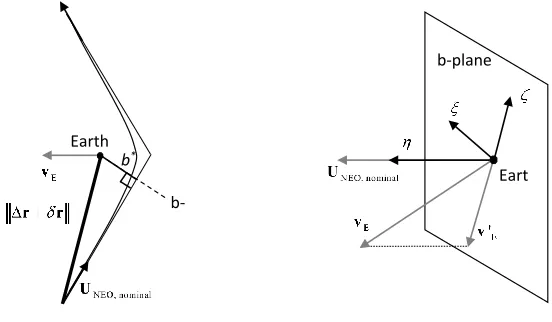
From the deflectionδrthe impact parameterbon the impact plane at the time of the MOID can be computed. The impact plane can be defined as the plane centered in the Earth and perpendicular to the velocity vector of the undeviated asteroid with respect to the Earth,Uneo, at the time of the impact (see Fig.1wherevE is the velocity of the Earth). The simplifying assumption
is that the velocity vector of the deflected asteroid remains parallel to the one of the undeflected asteroid at the MOID. The deflection vectorxb in the
b-plane coordinates can be expressed as:
xb(tmoid) = [ξ η ζ]
T =h
b
ξ bη ζb
iT
δr=Bδr (4)
where
b
η = UN EO
UN EO
, ξˆ= vE ∧bη
kvE ∧bηk
, ζˆ=ξb∧ b η
If one then calls δæ = [δa, δe, δI, δω, δΩ, δM]T the vector of the variations of the parameters, and A and Gthe two matrices such that δæ = Gδv and
δr(tmoid) = Aδæ then we have:
xb(tmoid) =BAGδv (5)
with the impact parameter b:
b =pξ2+ζ2 (6)
Note that other deflection formulas can be derived from Eq. (8) by assuming for example that the deflection is not introducing any geometric variation on the b-plane but only a temporal variation δMn. However, retaining only
the temporal variation precludes the possibility to study deflection actions with short warning times or leading to relatively small variations of the semi-major axis. Furthermore, when the asteroid’s orbit is tangent to the one of the Earth and the undeflected asteroid is due to collide, a change in the orbital period would result in a zero variation of the b parameter although a collision is temporary avoided. This highlights the importance of all the components of the xb vector as explained in Vasile and Colombo (2008).
2.2. Slow-Push Deflection
b-plane Earth
b*
b-plane
[image:6.612.145.421.169.330.2]Eart
Figure 1: The b-plane and the impact parameter b
until the time te when the deflection action stops: da
dL =
2a3B2 µ
(P2sinL−P1cosL) Φ2(L) ur+
1 Φ(L)ut
dP1
dL =
B4a2 µ
−cosL Φ2(L)ur+
P1+ sinL
Φ3(L) +
sinL
Φ2(L)
ut
+
−P2
Q1cosL−Q2sinL
Φ3(L) uh
dP2
dL =
B4a2 µ
sinL
Φ2(L)ur+
P2+ cosL
Φ3(L) +
cosL
Φ2(L)
ut
+
P1Q1cosL−Q2sinL
Φ3(L) uh
dQ1
dL =
B4a2
2µ 1 +Q 2 1+Q22
sinL
Φ3(L)uh
dQ2
dL =
B4a2
2µ 1 +Q 2
1+Q
2 2
cosL
Φ3(L)uh dt dL = s a3 µ B3
Φ2(L)
(7)
whereLis the true longitude, B =p1 +P2
1 +P22 and Φ(L) = 1 +P1sinL+ P2cosL. The integration can be performed analytically, using the asymptotic
expansions in Zuiani et al. (2012), or numerically, and then converted into the corresponding variation of the orbital elements. Note that when the integration is numerical it is more convenient to use the variation of the elements in time, while the analytical integration is in the true longitude. For further details, please refer to Zuiani and Vasile (2015). Equations (1) and (4) are then applied to give:
xb(tmoid) =BA
Z te
td
Gudt (8)
It is worth recalling that the variation of the mean anomaly in this case is given by:
δM = (ne−n)tmoid+ntd−nete+ ∆M (9)
where ∆M is the time integral of the geometric part and
ne =
r µ
.
3. Deflection Methods
In this section we revise some existing models of deflection actions and their variants and introduce a discussion on their applicability and effective-ness. The discussion will allow us to short-list only four methods that will then be applied to the selected sample of virtual impactors.
3.1. Kinetic Impactor
The idea of the kinetic impactor is to impart a slight alteration in the velocity of an asteroid by colliding a spacecraft into it at high speed. The simplest version of this deflection concept assumes a direct injection (single impulse) into an interception trajectory from the Earth to the asteroid. In this paper the trajectory is calculated as the solution of a multi-revolution Lambert arc. Therefore, the mass ms/c of the spacecraft and its relative
velocity δvs/c at the deflection date td are a function of both the time of
flight ToF and departure datetD from the Earth as well as the interplanetary
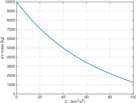
injection capability of the launcher. Figure 2 shows the launch capability of
C3 [km2/s2]
0 20 40 60 80 100
s/c mass [kg]
[image:8.612.184.412.420.593.2]0 1000 2000 3000 4000 5000 6000 7000 8000 9000 10000
Figure 2: Spacecraft mass ms/c as a function of thec3 escape energy from the regression
laws ofWise et al.(2010) for the Delta IV Heavy - RS-68A upgrade version
The variation of velocity imparted by the spacecraft to the asteroid is then computed with a simple conservation of momentum equation, assuming a momentum enhancement factor β = 1:
δv =βms/c
ma
δvs/c (10)
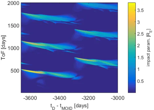
Once the variation of the velocity is available, formulae (1) to (8) can be used to compute the impact parameter. As an illustrative example, Figure3
[image:9.612.180.429.311.489.2]shows the achieved impact parameter b as a function of departure date and time of flight considering a kinetic impactor injected into a transfer orbit by a Delta 4 Heavy rocket to a virtual version of 2011AG51.
Figure 3: Impact parameter as a function of the departure datetD and time of flightT oF
for 2011AG5
3.2. Ion Beaming
Ion beaming was proposed byBombardelli et al.(2013) as a technique to deflect asteroid with the name Ion Beam Shepherd (IBS). The idea is to use an ion engine to transfer momentum to the asteroid by beaming a flow of ions. In order to maintain the relative position between the deflecting spacecraft and the asteroid, a second engine needs to be positioned on the opposite
side of the spacecraft to balance the thrust coming from the engine beaming the ions on the PHA. In the following we assume a momentum transfer efficiency of 1, which means that all the ions are impinging the asteroid, negligible gravity tugging effect at the operation distance (less than 10mN for distances larger than 500m) and the same thrust for the two engines. The acceleration imparted onto the asteroid is then plugged into equations (7) to get the resulting deflection.
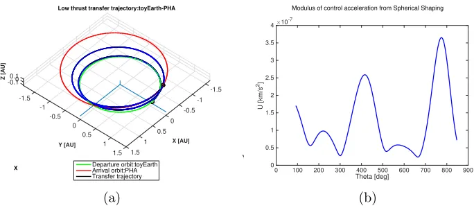
A low-thrust transfer is considered in the case of this method, which allows using the electric propulsion system also during the transfer phase. The spherical shaping method introduced in the work of Novak and Vasile
(2011) was used to compute low-cost, low-thrust trajectories as a function of the T oF and departure epoch for the the mission. An example of calculated trajectory to asteroid 2011AG5, requiring a ∆v of 7.8 km/s is shown in Fig.
4. Y -1.5 -1 -0.5 X [AU] Low thrust transfer trajectory:toyEarth-PHA
0 0.5 1 1.5 1.5 1 0.5 0 Y [AU] -0.5 -1 -1.5 -0.10.10
X Z [AU] Departure orbit:toyEarth Arrival orbit:PHA Transfer trajectory (a)
Modulus of control acceleration from Spherical Shaping
Theta [deg]
0 100 200 300 400 500 600 700 800 900
U [km/s
2] ×10-7
[image:10.612.135.477.349.499.2]0 0.5 1 1.5 2 2.5 3 3.5 4 (b)
Figure 4: Example of calculated low thrust transfer trajectory and modulus of the control acceleration with the spherical shaping method forT oF = 847 days andtD=−3615 days
before virtual impact with 2011AG5
Considering an Isp of 3000 s and given a departure mass, our algorithm
phase but also penalises the amount of propellant mass that will be available during the deflection phase since more mass needs to be allocated to the different subsystems.
Efficient (30% from solar to electrical power) triple junction solar arrays are assumed in our study. In line with the predicted performance of Orbital ATK’s UltraFlex and Megaflex arrays, we consider a specific array mass of 10 kg/kW throughout this study, scaling with the power required at 1 AU. An additional 5 kg/kW, scaling with the peak power at perihelion, models the other components of the power subsystem, including PCDU.
Typically, the Electric Propulsion Subsystem (EPS) comprises three core elements:
1. Thruster assembly which includes in this case the thrusters and the gimbals on which they can be mounted to control the thrust orientation. A specific mass of 2 kg/kW together with a thrust to power ratio of 46 mN/kW are considered in the calculations and the thrusters are sized with respect to the peak thrust delivered during mission.
2. Power Processing Unit (PPU) which supplies the high voltage current required for the ion engines to work efficiently. The Thruster Selection Unit (TSU) itself allows to select the thruster fed by the PPU. The PPU/TSU is assumed to scale with the peak power during the mission with a specific mass amounting to 6 kg/kW.
3. Xenon Feed System (XFS) or Flow Control Unit (FCU) which usually includes a high pressure tank, a Xenon Control Assembly (XCA) which regulates the pressure and Xenon flow rate to the thrusters and the plenum tanks. The mass of the XFS is assumed to scale with the peak thrust with a specific mass of 1 kg/kW, which excludes the Xenon tank which itself is assumed to scale linearly with the propellant mass. The Dawn Xenon tank had a volume of 269L, could store up to 425 kg of Xenon and had a mass of 21.6 kg, giving a tankage fraction of 5%. A parametric mass model was also considered for the other subsystems, in-cluding harness (5% of the wet mass), structure (20% of the dry mass), AOCS (5% of the wet mass), as well as a non-scalable mass of 50 kg to telecommu-nications and data handling. Radiators are also scaled with respect to the maximum available power, considering a heat sink of 50% of the available power, ability of the radiator to re-radiate 400W per square meter and an areal density of 5 kg/m2. Eventually, any remaining mass is allocated to the
Power
EPS
AOCS
Telecom&Data handling
Struct.
Harness
Thermal
[image:12.612.208.388.129.312.2]Xenon Propellant Wet S/C Mass= 1000 kgs, Swarm population = 1
Figure 5: IBS mass budget for T oF = 847 days and tD = −3615 days before virtual
impact with 2011AG5 and an oversizing factor of 1
the mass required to increase the size of the tanks and structure). If no mass is left prior to that step, the mission is considered infeasible with that partic-ular combination of departure date, time of flight and oversising coefficient. Considering a wet mass of 1000 kg, the transfer of Fig. 4, as well as an oversising factor of 1, Fig. 5 illustrates the resulting mass budget. The IBS spacecraft for this particular scenario would be able to generate a nominal thrust (in deflection mode) of 110 mN and nominal input power level of 4.78 kW at a distance of 1 AU from the Sun.
The deflection phase starts as soon as the spacecraft has rendezvoused with the PHA. During that phase, it is assumed that the engines work at the maximum of their capability given the available power generated by the solar arrays at the current distance from the sun. Only half of the thrust can be used for the deflection as the other half is needed for station-keeping of the IBS. The acceleration on the asteroid is assumed to be also imparted in the tangential direction in average and is computed by
ut =
Fibs
ma (11)
The time of the end of the application of the deflection action is set to the time of the virtual impact tmoid although if, at some point during the deflection, the propellant allocated to the deflection action goes to zero, the deflection action terminates and a null acceleration is considered for the remaining part of the integration.
3.3. Laser Ablation
The laser ablation deflection method aims at exploiting the material the asteroid is made of in order to generate the required thrust. The ablated ma-terial forms a plume of vaporized mama-terial which, due to the action/reaction principle, creates a controllable and continuous thrust on the asteroid.
With the power depending on efficient (30% from solar to electrical power) triple junction solar arrays, the level of thrust is again modulated by the square of the distance to the sun during the deflection phase, which is as-sumed to start as soon as the spacecraft arrives to the asteroid. The con-version from input power to ablative thrust Fabl on the asteroid is computed
through the formula
FLS =ηLSCmPin (12)
In which ηLS is the electrical to optical (E/O) conversion efficiency of the
laser system and Cm, the thrust coupling coefficient, which is known to vary
between 10 to 100 µN/Woptical for most materials (Phipps, 2011). E/O
effi-ciencies>39% have already been demonstrated by multi-kW spectrally beam combined fiber-coupled diode lasers (Honea et al., 2013). Focused develop-ment under the DARPA SHEDs program has also lead to extremely high power conversion efficiency in the 9xx-nm wavelength band, leading to diode bars with efficiency in excess of 74% and a clear route to efficiencies supe-rior to 85% at room temperature (Crump et al., 2007). With demonstrated slope efficiency of optical fibers on the order of 80% (Jeong et al., 2004) and a demonstrated efficiency of spectral beam combining techniques of 91%
(Drachenberg et al., 2011), we consider in this paper a global E/O efficiency
of 50%.
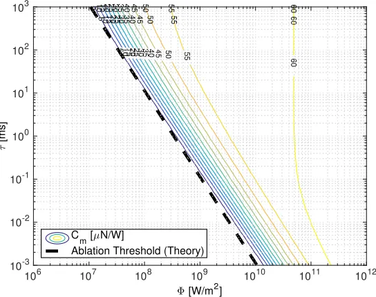
Detailed calculations performed on Forsterite byThiry et al. (2016) indi-cate that the coupling coefficient of a CW laser operating under the plasma formation intensity near the 1 micron wavelength is dictated mainly by 2 parameters: the laser intensity Φ [W/m2] which depends on the laser output
5 5 5 10 10 10 15 15 15 20 20 20 25 25 25 30 30 30 35 35 35 40 40 40 45 45 45 50 50 50 55 55 55 60 60 60
Φ [W/m2]
106 107 108 109 1010 1011 1012
τ [ms] 10-3 10-2 10-1 100 101 102 103 C
m [µN/W]
[image:14.612.166.438.138.353.2]Ablation Threshold (Theory)
Figure 6: Thrust coupling coefficient Cm as a function of the mean heating time τ and
beam power density Φ for a CW laser fromThiry et al.(2016)
beam diameter and the relative speed of the asteroid surface with respect to the laser beam (on the order of 6 cm/s if one considers the spin-limit of a 156 m asteroid). Fig. 6 shows the result of these calculation for Forsterite, a main constituent of S-type asteroids which are thought to dominate the population in the inner belt. For typical mean heating times on the order of 10–100 ms and typical CW laser beam intensities on the order of 1 GW/m2
envisioned in our laser system, one can see from this chart that the thrust coupling has a value around 55–60µ N/W and will only be weakly affected by the temporal changes in operating conditions due to the variation of input power with respect to the square distance to the sun. To generate the inten-sity levels required, the optics should be designed using the diffraction limit focusing capability at the shooting distance. The optical components should also be designed so that they are exposed to intensity levels well under their damage threshold. As an example, an optics with a primary mirror of 60cm diameter would be enough to generate a 3 mm laser spot at a 1km shooting distance. For a 10 kW laser, this would correspond to an intensity of 1.4 GW/m2 at the focal spot, but only 35 kW/m2 on the primary mirror.
irra-Symbol: Mg Fe Si O C Mg2SiO4 Fe2SiO4
Name: Magnesium Iron Silicon Oxygen Carbon Forsterite Fayalite
A: 24 26 28 16 12 -
-Copt
[image:15.612.108.501.127.187.2]mp (µN/W): 80 83 86 67 59 75(avg.) 79(avg.)
Table 1: Optimal thrust coupling predicted by Eq.13for various materials encountered in asteroids
diation below intensity levels of 10 GW/m2, which are required to accelerate
the free electrons in the vapor by inverse Bremsstrahlung until their kinetic energy becomes sufficient to ionize the atoms of the vapor by an avalanche process, according to Poueyo-Verwaerde et al. (1993). A model to predict the thrust coupling coefficient in the Plasma regime has been developed by
Phipps et al. (1988) for pulsed laser systems and it is interesting to
com-pare the peak coupling predicted by this model with the values predicted by our CW model. In this model, the plasma coupling Cmp coefficient was
empirically found to follow a power law:
Cmp(µN/W)≈184
Ψ9/16
A1/8(Φλ√τ)1/4 (13)
in which τ is the pulse duration, λ the laser wavelength and Ψ depends on the average atomic number A and the average ionization state Z as:
Ψ = A
2 (Z2(Z+ 1))1/3 (14)
Phipps et al. (1988) noted that the optimal coupling happens for values of
intensity and pulse duration such that Φ√τ = 8.5E+08 Ws1/2/m2, which
will consider a conservative value of 40 µN/W, accounting also for possible loss due to the shape irregularity of the asteroid and the fact that the laser ablation thrust can only be oriented in the desired direction tangential with respect to the PHA trajectory in average. In fact, as explained by Vetrisano
et al. (2015, 2016) a smart laser steering strategy would allow to improve
further the thrust directional efficiency.
Laser Syst.
Power
EPS
AOCS
Telecom&Data handling Struct.
Harness Thermal Xenon Propellant
[image:16.612.212.412.227.413.2]Wet S/C Mass= 1000 kgs, Swarm population = 1
Figure 7: LS mass budget forT oF = 847days andtD=−3615 days before virtual impact
with 2011AG5
as for the IBS, a summary of the mass budget considering a wet mass of 1000 kg is given in Figure7. For this specific case, the laser system would deliver an estimated nominal ablative thrust of 168 mN and nominal input power level of 8.4kW at a distance of 1AU from the Sun. For comparison, NASA’s Dawn spacecraft, which recently visited the dwarf planet Ceres using 3 NSTAR gridded ion-thrusters and achieved a record cumulated ∆v of 14 km/s, had a wet mass of 1240 kg with 425 kg of Xenon propellant, a dry spacecraft mass of 815 kg and a solar array of 36.4 m2 able to deliver 10.3 kW at 1 AU.
Finally, the deflection is computed as in the case of the IBS, except that the acceleration is imparted for the whole duration until the virtual impact epoch tmoid. As in the case of the IBS method, tugging forces are considered negligible at the operation distance (less than 3mN for distances larger than 1km).
3.3.1. Contamination Considerations
According to previous studies (Gibbings et al., 2013), the impingement with the plume of gas and debris, generated by the ablation process, could build up enough material on the surface of the solar arrays to reduce the output power below the ablation threshold. At the same time it was shown that this contamination has a limited impact on the laser itself and related optics. Furthermore, as shown in the ESA LightTouch2 study (Vasile et al.,
2013), by properly positioning the spacecraft with respect to the asteroid, aligning the arrays with the plume and adding Whipple shields the effect of contamination can be mitigated to the point that they can be considered negligible over the lifetime considered in this paper.
3.4. Gravity Tractor
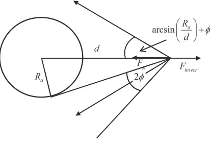
fixed, the gravity force must equate the net thrust Fhover:
Fhover= 2TScos
arcsin
Ra
d
+φ
(15)
Fg =
GmamS(t)
d2 (16)
Fhover=Fg (17)
where TS is the thrust of a single engine in the slanted configuration, φ the
half-divergence angle of the engine, Ra is the radius of the asteroid, ma its
mass, G the gravity constant and m(t) is the mass of the spacecraft at time t. The tugging acceleration is simply:
ugtug(t) =
GmS(t)
d2 (18)
If the engines are assumed to be always on and the initial mass of the space-craft is mi, the mass of the spacecraft at time t can be expressed as:
mS(t) =miexp −
Gma(t−t0) d2cos arcsin Ra
d
+φIspg0 !
(19)
whereIsp is the specific impulse of the engine andg0 the gravity acceleration
on the surface of the Earth and t0 is the beginning of the deflection action.
[image:18.612.206.413.486.627.2]
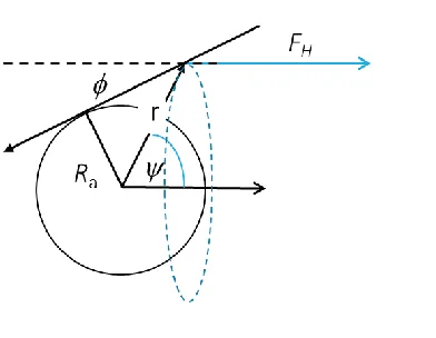
Figure 9: Sketch of the gravity tug approach with halo configuration
In McInnes (2007) and Yamaguchi and Yamakawa (2014) a variant of
the original gravity tractor concept was proposed to remove the need for a slanted configuration and to use the thrust more efficiently. The idea is to place the tractor on a displaced halo orbit that is artificially maintained by a constant thrust. If the plume of gas of the engine generating the thrust is not impinging the asteroid, the net result is traction on the asteroid in the direction of the thrust vector (see Figure 9). Compared to the slanted configuration, the halo configuration requires only one engine but the thrust delivered by the engine has to be lower or the distance from the asteroid has to be shorter.
With reference to Figure9, the achievable tugging effect as a function of the divergence angle φ is:
uH =
GmH(t) R2
a
cosψsin(ψ−φ)2 = GmH(t)
R2 a
τ (20)
The τ factor in (20) is represented in Figure10 for different values ofφ. The figures shows thatτ cannot be 1 for any value of ψ. The maximum is in fact about 0.385 and is realised when φ= 0. In comparison the slanted configuration can reach a theoretical τ = 1 for an infinite thrust.
ψ [rad]
0 0.2 0.4 0.6 0.8 1 1.2 1.4 1.6
τ
0 0.05 0.1 0.15 0.2 0.25 0.3 0.35 0.4
φ=0o
φ=10o
[image:20.612.187.422.139.327.2]φ=25o
Figure 10: τ factor as a function ofψ
spacecraft is given by Eq. (19) and the tugging force is:
Fg =
Gmamie
− Gma∆t
Ispg0d2 cosα
d2 = 2TScosα =TH (21)
where α = arcsin Ra
d
+φ, ∆t = t−t0 and the further assumption is that
the thrust of the halo configuration follows the same time law of the tugging force given by the slated configuration. As a result the variation of mass of the halo configuration is:
˙
mH =−c
Gmamie
−cGma∆t
d2 cosα
d2 =−
cGmami
d2 e
−A∆t (22)
with c= 1/(Ispg0) and:
A= cGma
d2cosα (23)
The mass of the halo spacecraft as a function of time results to be:
mH −mH0 =
cGmami
d2
e−A∆t
A =micosαe
−A∆t−m
icosα (24)
If the initial mass of the halo and slanted configurations are the same, then:
ψ [rad]
0.2 0.4 0.6 0.8 1 1.2 1.4 1.6
d/r
1 2 3 4
∆
vS
/
∆
vH
0.7 0.8 0.9 1
d/r
[image:21.612.191.439.137.337.2]∆ vS/∆ vH
Figure 11: Relative distance and ∆v for two GT configurations
Given that both configurations generate the same tugging force, the total time to achieve a given deflection is the same and, therefore, the mass of the halo configuration is simply cosα lower than the mass of the slanted configuration.
The question is now whether for a fixed distance and equal traction the halo configuration can deliver a higher or lower ∆v than the slated configu-ration. To this end, one can calculate the distance d that provides the same traction aH for different ψ and the corresponding ∆v for the two
configura-tions. Given equation (20) one can calculate the mass of the halo spacecraft as:
mH(t) =mH0e
Gmaτ
R2aIspg0t (26)
From the mass consumption one can derive the time at which the deflection action stops by assuming a mass fraction for the available propellent:
tH = log
mH(tH) mH0
R2aIspg0
Gmaτ
(27)
the ∆vH, which is simply:
∆vH = mH0e
Gmaτ R2aIspg0tH
ma
= mH(tH)
ma
(28)
A similar procedure can be used to calculate the ∆vS inserting (19) into
(18) and integrating with respect to time. Figure11shows the ratio between the ∆vS delivered by the slant configuration and the one delivered by the
halo configuration. On the same plot the ratio between the distance d and the distance r is also shown. As ψ goes to π/2, r approaches Ra but the
traction goes to zero therefore d goes to infinity. On the other hand as ψ
approaches 0 asymptotically both r and d go to infinity. The figures shows that for a fixed distance and equal traction the halo configuration always delivers a higher ∆v. Note however that the traction time is proportionally longer for the halo configuration. For a reference ∆v of 1 km/s the slant configuration is 6 to 7% faster than the halo configuration.
In conclusion while the halo configuration uses less propellant mass for the same traction, the slanted configuration can achieve higher tractions in a shorter amount of time.
In the following we will use the halo configuration with an assumed di-vergence angle of 10◦ for our comparison as in Sanchez et al. (2009) an op-timised slanted configuration was considered instead. Practically speaking, our model of the GT method was adapted from the IBS model to consider a time-dependent maximum tugging thrust during the integration of the de-flected orbit. This model also considers that engines are only required on one side of the GT (for station keeping) contrary to the IBS which requires engines on both sides of the spacecraft.
4. Theoretical Considerations
In this section we provide a theoretical analysis of the energy required to increase the transfer of momentum during impact. In other words we consider the case in which the orbit of the impactor is modified so that the relative velocity between spacecraft and asteroid at impact is increased.
velocity of the asteroid post impact with the spacecraft is:
δv= ms/c
ma
(kqk −∆vT) (29)
where q is the difference in velocity due to the difference between the orbit of the asteroid and the one of the Earth:
q=
r
2µ rE
− µ
aa
−
r µ rE
(30)
and ∆vT is the increment due to the transfer of the spacecraft on a suitable
orbit:
∆vT = r
2µ rE
− µ
rE +δaN
−
r µ rE
(31) .
The mass of the spacecraft at impactms/c can be related to the mass at
launch msi through:
ms/c msi
=e−
∆vT
Ispg0 (32)
from which:
δv = msie
−Ispg∆vT
0
ma
(kqk −∆vT) (33)
Figures 12a and 12b show the δv for different asteroid semi-major axes, aa,
and different ∆vT, in the case of an Isp = 300s and an Isp = 3000s
respec-tively. The figures show that for a low Isp the optimal strategy is not to
perform any transfer as the increase in momentum is proportional to ∆vT
but the loss in mass is proportion to e−∆vT. This is a problem for asteroids
with semi-major axis close to 1AU, low eccentricity and low inclination as a transfer produces a low gain in δv and a further increase in ∆vT might in
fact lead to a decrease in the deflection.
The situation appears to be different for a high Isp. In this case the
gain provided by the transfer for high aa is limited but the one provided
for low aa becomes interesting. Note that this analysis does not consider
gravity losses and the time required to deliver the required ∆vT. Figure 13
shows the difference between the ∆v required to rendezvous with the asteroid and ∆vT. A positive ∆∆v indicates that a rendezvous is more expensive.
slow push method. The figure gives an indication of when a kinetic impactor might be preferable to a slow-push technique. Another qualitative indication can be obtained by computing the required propellant mass to generate the same change in linear momentum given by a kinetic impactor. Assuming a constant low-thrust push on an asteroid, the mass of propellant required to deliver the variation of linear momentum in Eq. (32) is given by:
∆mIspg0 =msie
−Ispg∆vT
0(kqk −∆vT) (34)
to this, one has to add the mass required to inject the spacecraft into the orbit of the asteroid:
∆mLT =msi e−
∆vT
Ispg0(kqk −∆vT) Ispg0
+msi(1−e
−Ispgq
0) (35)
The mass of the propellent on the kinetic impactor is instead given by Eq. (32) which then gives the relative mass fraction:
∆mLT
∆mKI
=
e−
∆vT
Ispg0(kqk−∆vT)
Ispg0 + (1−e
−Ispgq
0)
(1−e−
∆vT
Ispg0)
(36)
The relative mass fraction for an Isp=3000s can be seen in Figure 14. The
figure shows that, in this particular case, when the orbit of the asteroid approaches the one of the Earth the slow-push solution is up to 20% more ef-ficient, which translates into 20% more deflection action, than increasing the energy of the kinetic impactor, albeit with a low-thrust propulsion system. It has to be noted that although this analysis is limited to a special case, some considerations are generally applicable. In particular, a highly inclined orbit favours a kinetic impactor in the same way an orbit with a high aa
does. On the contrary, for a shallow crosser with a low inclination, the mass loss coming from the rendezvous with the asteroid is limited compared to the increase in orbital energy of the kinetic impactor. Finally, if the slow-push action did not require any propellent at all the first term on the right hand side of Eq. (35) would translate in an additional % of deflection.
low-thrust transfer for the kinetic impact become progressively more inter-esting as the propellant cost decreases (or theIsp increases). For this reason,
solutions using solar sails or electromagnetic sails have been considered in the past. These solutions, however, require careful considerations on the de-sign of the navigation and control system to guarantee a successful impact at hyper-velocity due to the limited control authority. At the same time one can argue that if a slow push method requires low or zero propellant to deliver the required deflection action, then that method might be optimal in the case of low semimajor axis, low eccentricity and low inclination asteroids. Furthermore, if one combines a low-cost transfer with a zero-propellent slow push method then slow push become optimal for a wide range of targets.
-9.5 -9 -8.5 -8 -7.5 -7 -6.5 -6 -5.5 -5 -4.5 -4 -3.5 -3 -2.5 -2 -1.5 -1 -0.5 0 0.5 1 1.5 2 2.5 3
3.5 4.5 4
5 5.56.5 7 6
δ v [mm/s] - I
sp=300s
∆ v T [km/s]
-4 -2 0 2 4 6 8 10 12
aa [AU] 1 1.5 2 2.5 3 3.5 -8 -6 -4 -2 0 2 4 6
(a)Isp= 300s
-12 -11.5 -11 -10.5 -10 -9.5 -9 -8.5 -8 -7.5 -7 -6.5 -6 -5.5 -5 -4.5 -4 -3.5 -3 -2.5 -2 -1.5 -1 -0.5 0 0.5 1 1.5 2 2.5 3 3.5 4 4.5 5 5.5 6 6.5 7 7.5 8 8.5 9 9.5 10 10.5
1112 11.5 δ v [mm/s] - I
sp=3000s
∆ v T [km/s]
-4 -2 0 2 4 6 8 10 12
aa [AU] 1 1.5 2 2.5 3 3.5 -10 -5 0 5 10
[image:26.612.154.451.179.559.2](b)Isp= 3000s
Figure 12: Deflectionδv for different semi-major axes and different ∆vT: a) contour lines
of achievable δv imparted onto the asteroid given a departure ∆vT and asteroid
semi-major axisaa for an engineIsp= 300s, b)contour lines of achievableδv imparted onto the
∆∆v [km/s]
∆ v T [km/s]
-4 -2 0 2 4 6 8 10 12
aa
[AU]
1 1.5 2 2.5 3 3.5
[image:27.612.156.450.134.298.2]-12 -10 -8 -6 -4 -2 0 2 4 6 8
Figure 13: ∆∆vfor different semi-major axes and different ∆vT: negative values indicate
that a low-thrust tug is preferable to a kinetic impactor.
Relative mass fraction ∆m
LT/∆ mKI
-5 0 5 10
∆ v
T [km/s]
1 1.5 2 2.5 3 3.5
a a
[AU]
0.82 0.84 0.86 0.88 0.9 0.92 0.94 0.96 0.98 1
[image:27.612.140.459.351.611.2]5. Asteroid Sampling Strategy
This section explains how we selected the asteroids forming the test set to compare the performance of different deflection methods.
5.1. PHA Distribution
As in the work of Bach (2012), the undeflected motion of the PHAs considered in this work is approximated by Keplerian orbits in a heliocentric frame and the Earth orbit is approximated with an exact circle of radius 1AU. Intuitively, this simplification induces two necessary but not sufficient conditions on the semi-major axis a and eccentricity e for impacting PHAs:
a(1−e)<1 AU and a(1 +e)>1 AU (37)
Using the criterion in Eq. (37), we extracted 8273 Earth-crossing NEAs from the NEODyS database presently maintained at the University of Pisa2.
The distribution of these NEAs can be seen on Fig. 15where the green lines represent the necessary crossing condition of Eq. (37).
a [AU]
1 1.5 2 2.5 3 3.5
e
0.2 0.4 0.6 0.8
[image:28.612.191.409.401.579.2]0 20 40 60 80 100
Figure 15: Distribution in semi-major axis and eccentricity of all known NEAs with an orbit crossing the heliocentric sphere of radius 1 AU
2
5.2. Virtual Impactor Model
Fixing the semi-major axis, eccentricity and inclination with their actual value from the extracted database, one independent element remaining to fix is the longitude of the ascending node node Ω of the PHA’s orbital plane with respect to the ecliptic. However, since we neglect the small minute Earth orbit eccentricity, the impact epoch is arbitrary and we can choose to fix Ω = 0 so that the PHA’s orbital planes crosses the ecliptic along the vernal equinox direction. The last parameters to fix are the argument of perihelion
ω and the true anomaly θ of the PHA at the impact epoch tmoid. From the above simplifications, the argument of perihelion and the true anomaly may only adopt two distinct values to respect the impact condition:
1AU = a(1−e
2)
1 +ecosω and θ= 2π−ω (38)
The two solutions of Eq. (38) correspond to an impact with the ascending or the descending branch of the PHA respectively.
5.3. Sampling Strategy
We formed a sample of virtual impactors by randomly selecting 100 PHAs in the NEODyS database, using the method described in Sec. 5.2 and con-sidering an equal probability of impact with the ascending or the descending branch of the PHAs. The distributions in semi-major axis, eccentricity and inclination of this test sample are plotted for further reference in Fig. 16.
semi-major axis [AU]
0.5 1 1.5 2 2.5 3 3.5
#PHAs
0 2 4 6 8 10 12 14 16 18 20
(a) semi-major axis
eccentricity
0 0.2 0.4 0.6 0.8 1
#PHAs
0 5 10 15 20 25
(b) eccentricity
inclination [deg.]
0 10 20 30 40 50 60
#PHAs
0 5 10 15 20 25 30
[image:29.612.116.500.492.612.2](c) inclination
6. Global Optimisation Strategies
The optimisation of the deflection strategies requires the global explo-ration of the parameter space. Furthermore, it is desirable to investigate the trade-off between warning time and achievable miss distance. For this reason we used two global optimisation procedures one for single objective and the other for multi-objective optimisation of multi-modal functions: MP-AIDEA
(Di Carlo et al., 2015) and MACS2 (Ricciardi and Vasile, 2015). In the
fol-lowing we briefly present how each optimisation approach works and how it was used in the context of this paper.
6.1. Optimisation with MP-AIDEA
For all methods, the impact parameter can be computed as a strongly non-linear function of the departure date tD and the time of flightT oF, but
also the oversizing coefficient in the case of the IBS method. For each mission scenario we globally explore the space of possible departure dates, transfer times and oversizing coefficients (in the case of the IBS) with a memetic algorithm called multi-population adaptive inflationary differential evolution algorithm (MP-AIDEA).
The decision variables handled by MP-AIDEA are the time of flight, ToF, and mission duration, tmission = tmoid − tD, and are limited by box
constrains. The time of flight represents the time between mission departure from the Earth and arrival at the satellite while the mission time is the total time between Earth departure and the time of virtual impact between the asteroid and the Earth. Table 2 reports for each optimisation associated to each deflection method (KI=Kinetic Impactor, IBD=Ion Beam Shepherd, LA=Laser Ablation), the box constraints on the decision variables T oF and
tmission, the number of agents per population used by MP-AIDEA to search
for the global optimum (#agents), the number populations (#pop) and total number of calls to the objective function (#fevals).
Method ToF (days) tmission (days) #agents #pop #fevals
KI [0, 1000] [1000, 3662.42] 10 4 10000
IBS [300, 2000] [2000, 3662.42] 15 4 1200
LA [300, 2000] [2000, 3662.42] 10 4 1000
Table 2: Parameters and box constrains used during the optimisation with MP-AIDEA
During each function evaluation, we also run an internal loop to evaluate the solution within the feasible range of number of revolutions for the trajec-tory computed by the Lambert solver and the spherical shaping algorithm. When more than one transfer are feasible for the combination ofT oF andtD,
our fitness function only returns the solution with the number of revolution that provides the best miss-distance.
6.2. Optimisation with MACS2
stores Pareto optimal solutions in an archive and shares information with the other agents in the population. For more specific information please refer to
Ricciardi and Vasile (2015).
MACS2 was used to optimise both the mission duration and the impact parameter. Therefore, one objective function was defined as:
obj1 =
n (b−2R
e)2 if b <2Re
0 otherwise
This definition forces the optimiser to find minimum time solutions that achieve at least a 2 Earth radii deflection. The other objective function was defined as:
obj2 = ToF +tdef l (39)
where tdef l = tmoid−td. Table 3 reports, for each optimisation associated
to each deflection method (KI=Kinetic Impactor, IBD=Ion Beam Shepherd, LA=Laser Ablation), the box constraints on the decision variables T oF and
tdef lt, the number of agents used by MACS2 to search for the Pareto set
(#agents), and total number of calls to the two objective functions (#fevals) where one function call evaluates both objectives at the same time.
Method ToF (days) tdefl (days) #agents #fevals
KI [0,1000] [0,3662.42] 150 14000
IBS [300,2000] [0,3662.42] 150 3000
[image:32.612.161.449.402.471.2]LA [300,2000] [0,3662.42] 150 3000
Table 3: Parameters and box constrains used during the optimisation with MACS2
6.3. Example with (99942) Apophis and 2011AG5
As an example of multi-objective optimization, we show here the Pareto fronts we obtained by considering the maximum miss-distance in minimizing the total duration from mission departure to the MOID epoch. The two aster-oids considered in this case are a down-scaled version of (99942) Apophis and the actual asteroid 2011AG5 previously considered by NEOSHIELD (2012). In both cases, the construction of the virtual impactor scenarios followed the approached detailed in section 5.2. The results are represented on Fig.
7. Results and Discussion
Using the methodology described in the previous section, we computed the maximum miss-distance within 10 years (tmoid−tD <10 years) with
MP-AIDEA and the minimum mission time (tmoid−tD) to achieve a miss-distance
superior to 2 Earth radii with MACS2.
The results of the maximum miss-distance obtained with MP-AIDEA can be seen in Fig. 18 for the case of a 156 m asteroid. The Kinetic impactor outperforms the other methods in 78% of the scenarios. The laser ablation method had the edge in the remaining 22% of the cases, which corresponded to asteroids with easily accessible orbits from the Earth (low eccentricity, inclination and orbital period close to 1 year). Note that the dots on this plot have a different inclination (coming from the sample distribution in a, e, and i) so that dots with similar semi-major axis and eccentricity may not necessarily produce a similar result on this 2D plot.
The results of the minimum time to achieve a 2 Earth radii (2RE)
deflec-tion can be seen in Fig. 19for the case of a 156 m asteroid. In this plot, red points indicate non-feasible deflection solutions within a range of 10 years be-tween departure date and MOID epoch. A total of 84 PHAs can be deflected by the Kinetic Impactor method, against 46 by the Laser Ablation strategy. Note that due to their low performance, the IBS and GT methods were not included in this second analysis. Interestingly, remark again that the KI method performs badly for a subset of virtual Impactor scenario having an orbital period close to 1 year and low eccentricity for which Laser Ablation possesses a superior deflection ability. This complementarity is highlighted if either the Kinetic Impactor or the Laser ablation can be considered. In that case, Fig. 19c shows that 95% of the PHAs can be deflected. The few asteroids that cannot be deflected in the prescribed time limit have an un-favourable phasing or are nearly tangent to the orbit of the Earth. Indeed, in these case we found that either the Kinetic Impactor or the Laser Ablation were falling short of 2 Earth radii limit although in some cases only by a few km.
8. Conclusion
It was demonstrated that the Kinetic Impactor outperforms the other tech-niques in the majority of the cases. However, detailed investigations reveal that the Kinetic Impactor performs badly for a subset of virtual impactors having an orbital period close to 1 year, a low eccentricity and a low inclina-tion.
For these cases, Laser Ablation offers a superior deflection ability (some-times by more than one order of magnitude). In all these cases low-cost transfer trajectories provide easy access to the asteroid and the major part of the spacecraft can be allocated to Power and Laser systems. In particular, if either the Kinetic Impactor or the Laser ablation can be considered, up to 95% of the PHAs can be deflected by over 2 Earth radii within a maximum duration of 10 years between departure date and epoch of the MOID.
Additional interest for these scenarios arises due to the fact that they represent possible targets for future exploration and exploitation missions. Therefore, our results plead for the parallel development of both technologies in the future. To be noted that, in this paper, the optimal transfer for low thrust propulsion was approximated with a spherical shaping algorithm. A better trajectory design might result in an improved performance of all slow-push methods.
Note that, since the deflection distance scales linearly with the the aster-oid mass and, as a first approximation, with the spacecraft mass, the authors expect that these choices will not impact the general conclusions of the paper. Future work will incorporate other interesting methods that have not been considered yet, like the kinetic impactor with low-thrust transfer and electrostatic tractors.
Acknowledgment
The work in this paper was partially supported by the Marie Curie FP7-PEOPLE-2012-ITN Stardust, grant agreement 317185. The authors express their gratitude to Niccol`o Gastaldello for implementing the Spherical Shaping algorithm used in this paper as well as Lorenzo Ricciardi and Marilena Di Carlo at the University of Strathclyde for their help in setting the parameters of MACS2 and MP-AIDEA.
References
Bombardelli, C., Urrutxua, H., Merino, M., Pel´aez, J., Ahedo, E., 2013. The ion beam shepherd: A new concept for asteroid deflection. Acta Astronau-tica 90 (1), 98–102.
Chapman, C. R., 2004. The hazard of near-earth asteroid impacts on earth. Earth and Planetary Science Letters 222 (1), 1–15.
Colombo, C., Vasile, M., Radice, G., 2009. Semi-analytical solution for the optimal low-thrust deflection of near-earth objects. Journal of Guidance, Control, and Dynamics 32 (4), 796–809.
Conway, B., 1997. Optimal low-thrust interception of earth-crossing aster-oids. Journal of Guidance Control and Dynamics 20 (5), 995–1002.
Crump, P., Dong, W., Grimshaw, M., Wang, J., Patterson, S., Wise, D., DeFranza, M., Elim, S., Zhang, S., Bougher, M., et al., 2007. 100+ w diode laser bars show >71% power conversion from 790 nm to 1000 nm and have clear route to >85%. In: Lasers and Applications in Science and Engineering. International Society for Optics and Photonics, pp. 64560M– 64560M.
Di Carlo, M., Vasile, M., Minisci, E., 2015. Multi-population inflationary differential evolution algorithm with adaptive local restart. In: IEEE Congress on Evolutionary Computation. pp. 632–639.
Drachenberg, D., Divliansky, I., Smirnov, V., Venus, G., Glebov, L., 2011. High-power spectral beam combining of fiber lasers with ultra high-spectral density by thermal tuning of volume bragg gratings. In: SPIE LASE. In-ternational Society for Optics and Photonics, pp. 79141F–79141F.
Gibbings, A., Vasile, M., Watson, I., Hopkins, J.-M., Burns, D., 2013. Ex-perimental analysis of laser ablated plumes for asteroid deflection and ex-ploitation. Acta Astronautica 90 (1), 85 – 97, NEO Planetary Defense: From Threat to Action.
Jeong, Y. e., Sahu, J., Payne, D., Nilsson, J., 2004. Ytterbium-doped large-core fiber laser with 1.36 kw continuous-wave output power. Optics Express 12 (25), 6088–6092.
Lu, E. T., Love1, S. G., 2005. Gravity tractor for towing asteroids. Na-ture (438), 177–178.
McInnes, C., 2007. Near earth object orbit modification using gravitational coupling. Journal of Guidance, Control and Dynamics 30, 870–873.
NEOSHIELD, 2012. D7.5.1: Trade offs of viable alternative mitigation con-cepts. Tech. rep., ASTRIUM UK.
Novak, D., Vasile, M., 2011. Improved shaping approach to the preliminary design of low-thrust trajectories. Journal of guidance, control, and dynam-ics 34 (1), 128–147.
Phipps, C., 2011. An alternate treatment of the vapor-plasma transition. International Journal of Aerospace Innovations 3 (1), 45–50.
Phipps, C., Albrecht, G., Friedman, H., Gavel, D., George, E., Murray, J., Ho, C., Priedhorsky, W., Michaelis, M., Reilly, J., 1996. Orion: Clearing near-earth space debris using a 20-kw, 530-nm, earth-based, repetitively pulsed laser. Laser and Particle Beams 14 (01), 1–44.
Phipps, C., Turner, T., Harrison, R., York, G., Osborne, W., Anderson, G., Corlis, X., Haynes, L., Steele, H., Spicochi, K., et al., 1988. Impulse cou-pling to targets in vacuum by krf, hf, and co2 single-pulse lasers. Journal of Applied Physics 64 (3), 1083–1096.
Phipps, C. R., 2014. L adroit–a spaceborne ultraviolet laser system for space debris clearing. Acta Astronautica 104 (1), 243–255.
Poueyo-Verwaerde, A., Fabbro, R., Deshors, G., De Frutos, A., Orza, J., 1993. Experimental study of laser-induced plasma in welding conditions with continuous co2 laser. Journal of applied physics 74 (9), 5773–5780.
Rosen, D., Mitteldorf, J., Kothandaraman, G., Pirri, A., Pugh, E., 1982. Coupling of pulsed 0.35-µm laser radiation to aluminum alloys. Journal of applied Physics 53 (4), 3190–3200.
Sanchez, P., Colombo, C., Vasile, M., Radice, G., 2009. Multicriteria compar-ison among several mitigation strategies for dangerous near-earth objects. Journal of Guidance, Control, and Dynamics 32 (1), 121–142.
Tedeschi, W., Remo, J., Schulze, J., Young, R., 1995. Experimental hyper-velocity impact effects on simulated planetesimal materials. International Journal of Impact Engineering 17 (4-6), 837–848.
Thiry, N., Vasile, M., Monchieri, E., 2016. Mission and system design for the manipulation of phos with space-borne lasers. In: IEEE Aerospace Conference. pp. 1–13.
Vasile, M., Colombo, C., July 2008. Optimal impact strategies for asteroid deflection. Journal of Guidance, Control, and Dynamics 31 (4).
Vasile, M., Gibbings, A., Massimo, V., Sanchez, J.-P., Yarnoz, D., Eckers-ley, S., Wayman, A., Branco, J., Burns, D., Hopkins, J.-M., Colombo, C., McInnes, C., 2013. Light Touch2: Effective solutions to asteroid manipu-lation, SYSNova Challenge Analysis Final Report. Tech. rep., University of Strathclyde.
Vetrisano, M., Cano, J. L., Thiry, N., Tardioli, C., Vasile, M., 2016. Optimal control of a space-borne laser system for a 100 m asteroid deflection under uncertainties. In: 2016 IEEE Aerospace Conference. IEEE, pp. 1–13.
Vetrisano, M., Thiry, N., Vasile, M., 2015. Detumbling large space debris via laser ablation. In: IEEE Aerospace Conference. pp. 1–10.
Wise, M., Lafleur, J., Saleh, J., 2010. Regression analysis of launch vehi-cle payload capability for interplanetary missions. In: 61st International Astronomical Congress.
Zuiani, F., Vasile, M., 2015. Extended analytical formulas for the perturbed keplerian motion under a constant control acceleration. Celestial Mechanics and Dynamical Astronomy 121 (3), 275–300.
tD-tMOID [days]
-4000 -3500 -3000 -2500 -2000 -1500 -1000 -500 0
impact param. [R
E ] 0 0.1 0.2 0.3 0.4 0.5 0.6
(a) Kinetic Impactor (Apophis)
tD-tMOID [days]
-4000 -3500 -3000 -2500 -2000 -1500 -1000 -500 0
impact param. [R
E ] 0 0.5 1 1.5 2 2.5 3 3.5 4
(b) Kinetic Impactor (2011AG5)
tD-tMOID [days]
-4000 -3500 -3000 -2500 -2000 -1500 -1000 -500 0
impact param. [R
E ] 0 0.1 0.2 0.3 0.4 0.5 0.6 0.7 0.8
(c) Ion Beam Shepherd (Apophis)
tD-tMOID [days]
-4000 -3500 -3000 -2500 -2000 -1500 -1000 -500 0
impact param. [R
E ] 0 0.2 0.4 0.6 0.8 1 1.2 1.4 1.6 1.8 2
(d) Ion Beam Shepherd (2011AG5)
tD-tMOID [days]
-4000 -3500 -3000 -2500 -2000 -1500 -1000 -500 0
impact param. [R
E ] 0 0.5 1 1.5 2 2.5 3 3.5 4 4.5
(e) Laser Ablation (Apophis)
tD-tMOID [days]
-4000 -3500 -3000 -2500 -2000 -1500 -1000 -500 0
impact param. [R
E ] 0 1 2 3 4 5 6 7
[image:39.612.133.468.139.619.2](f) Laser Ablation (2011AG5)
Figure 17: Maximum miss-distance and maximum departure date for the deflection of a 1010 kg, 212 m diameter Apophis-like asteroid (left) and a 4 ×10⁹ kg, 156 m diameter
semi-major axis [AU]
0.5 1 1.5 2 2.5 3 3.5
eccentricity 0 0.2 0.4 0.6 0.8
impact param. [R
E ] 5 10 15 20
(a) Kinetic Impactor
semi-major axis [AU]
0.5 1 1.5 2 2.5 3 3.5
eccentricity 0 0.2 0.4 0.6 0.8
impact param. [R
E ] 0.5 1 1.5 2
(b) Ion Beam Shepherd
semi-major axis [AU]
0.5 1 1.5 2 2.5 3 3.5
eccentricity 0 0.2 0.4 0.6 0.8
impact param. [R
E ] 2 4 6 8 10 12
(c) Laser Ablation System
semi-major axis [AU]
0.5 1 1.5 2 2.5 3 3.5
eccentricity 0 0.1 0.2 0.3 0.4 0.5 0.6 0.7 0.8 0.9
impact param. [R
E ] 0.05 0.1 0.15 0.2 0.25 0.3 0.35 0.4 0.45 0.5
[image:40.612.130.480.238.540.2](d) Gravity Tractor
semi-major axis [AU]
0.5 1 1.5 2 2.5 3 3.5
eccentricity
0 0.2 0.4 0.6 0.8
tD
- t
MOID
[years]
-9 -8 -7 -6 -5 -4 -3 -2
(a) Kinetic Impactor
semi-major axis [AU]
0.5 1 1.5 2 2.5 3 3.5
eccentricity
0 0.2 0.4 0.6 0.8
tD
- t
MOID
[years]
-10 -9 -8 -7 -6 -5
(b) Laser Ablation
semi-major axis [AU]
0.5 1 1.5 2 2.5 3 3.5
eccentricity
0 0.2 0.4 0.6 0.8
tD
- t
MOID
[years]
-9 -8 -7 -6 -5 -4 -3 -2
[image:41.612.133.476.237.524.2](c) Kinetic Impactor and Laser Ablation