City, University of London Institutional Repository
Citation
:
Ahmad, A.H., Naher, S. and Brabazon, D. (2014). The effect of direct thermal
method, temperature and time on microstructure of a cast aluminum alloy. Materials and
Manufacturing Processes, 29(2), pp. 134-139. doi: 10.1080/10426914.2013.822980
This is the unspecified version of the paper.
This version of the publication may differ from the final published
version.
Permanent repository link:
http://openaccess.city.ac.uk/3596/
Link to published version
:
http://dx.doi.org/10.1080/10426914.2013.822980
Copyright and reuse:
City Research Online aims to make research
outputs of City, University of London available to a wider audience.
Copyright and Moral Rights remain with the author(s) and/or copyright
holders. URLs from City Research Online may be freely distributed and
linked to.
City Research Online: http://openaccess.city.ac.uk/ [email protected]
The Effect of Direct Thermal Method, Temperature and Time on
Microstructure of a Cast Aluminium Alloy
A.H. AHMAD
1, 2, 3, S. NAHER
1, 2, 4*, and D. BRABAZON
1, 21
School of Mechanical and Manufacturing Engineering, Dublin City University, Dublin, Ireland
2
Advanced Processing Technology Research Centre, Dublin City University, Dublin, Ireland
3
Faculty of Mechanical Engineering, Universiti Malaysia Pahang, Pekan, Malaysia
4
School of Engineering and Mathematical Sciences, City University London, UK
The direct thermal method is used for the creation of globular microstructures suitable for semi-solid metal
forming. In this paper both simulation and experimental results using direct thermal method are presented.
ProCAST® software was used to estimate temperature distribution inside the aluminium billet. In validation
work, molten aluminium A356 was poured into metallic copper tube moulds and cooled down to the semi-solid
temperature before being quenched in water at room temperature. The effect of pouring temperatures of 630°C,
650°C, 665°C, 680°C and holding times of 45s and 60s on the microstructure of aluminium A356 alloy were
investigated. The simulation results showed that the average temperature rate within the copper mould, from
initial pouring temperature to just before quenching, was approximately 1°C/s. Examination of the solidified
microstructures showed that the microstructure was more spherical when lower pouring temperatures and holding
periods were used. From the micrographs it was found that the most globular and smallest structures were
achieved at processing parameters of 630°C and 45s.
Keywords:
Aluminium, A356, Direct Thermal Method, Pouring Temperature, Holding Time, Semi-Solid.
INTRODUCTION
Semi-solid metal processing has been commercially used
for the casting of various sizes of components on an
industrial scale. Commercial interests in semi-solid metal
processing are mainly in the automotive, aerospace, ICT,
plumbing and military supplier industries. This processing
technique has become a common casting method for
aluminium and magnesium alloys for producing high
density and high strength products [1]. Some current
research is also investigating ways to make this process
feasible for semi-solid steel forming [2]. The effect of
microstructure on fluidity which allows for semi-solid
processing was discovered by Flemings and Spenser in
Massachusetts Institute of Technology 40 years ago [3]. In
the initial stage, Flemings and his co-workers discovered
that the viscosity of the stirred material while in the
semi-solid forming was much lower than the viscosity
without stirring. It was also found that this lower viscosity
was due to the generation of a spherical grained structure in
the material from the stirred action during solidification.
Interlocking network of dendrite grains in the unstirred
material on the other hand generates a high viscosity fluid.
Semi-solid metal exhibits not only a shear rate thinning
________________
* Author to whom correspondence should be addressed. [email protected]
thixotropic in nature. This time dependency is mainly due
to disagglomeration of particles clusters after increased
shear rate processing or due to agglomeration of particles
after reduced shear rate processing [3]. The particles have a
natural affinity for each other and therefore agglomerate
during periods of the shearing. However, particle bonds are
re-melted during deformation as a result of shear stresses,
which allows the material to flow with greater ease.
The flow resistance of semi-solid metal is strongly depended
upon processing history. The resulting microstructure
(average grain size and shape and the distribution of grain
size) in semi-solid metal state and the degree of particle
agglomeration appear to be the most significant material
characteristics contributing to this process history dependent
flow behaviour.
Thermal treatment processing to obtain the required
microstructure for semi-solid metal forming is the most
commonly used commercial method to provide the required
globular microstructure. In order to achieve this, the creation
of many small nucleation sites is important. The higher the
number of nuclei, the smaller is the average distance
be-tween nuclei and the smaller are the resultant grains.
The new-rheocasting process by UBE technology is one
of the better known examples of this thermal method applied
commercially. In order to generate more nuclei, the molten
metal is chilled quickly from above the liquidus to below the
liquidus and held for a short holding at a semi-solid metal
temperature. This processes results in a very fine grained
microstructure. In the new-rheocasting process, the
semi-solid metal temperature is controlled with induction
heating to maintain the desired fraction solid [4]. The treated
semi-solid metal is then injected into the mould within the
die casting machine. The success of the new-rheocasting
process technique depends on the initial structure obtained
in the material. There are few more techniques that use a
similar principle in order to provide the required starting
material. These include the swirled enthalpy equilibrium
device [5], the continuous rheoconversion process [6], low
superheat pouring with a shear field [7], and the direct
thermal method [8].
In direct thermal method, liquid metal is poured into a
thin cylindrical metallic mould that has low thermal mass
and high conductivity [8]. Heat matching between molten
metal and mould allow for pseudo-isothermal hold within
the solidification range. This allows for the alloy to remain
in a steady semi-solid state where the temperature is held
between the solid and liquid phases of the alloy. This is
achieved by the very low rate of heat loss to the
environment through the mould, which is copper tubing with
a metal base plate. The advantage of this technique is that
the process uses the natural solidification principle and is
low cost. The low superheat of the alloy is extracted into
the mould such that the alloy rapidly cools into the
semi-solid zone. The initial rapid cooling gives rise to a high
rate of nucleation events in the alloy. After a short holding
period this microstructure spherodises. In order to capture
this microstructure, the mould is quenched into water at
room temperature while the alloy is still within the
semi-solid metal range.
Simulation using finite element method to
examine the heat distribution during solidification was
carried out by Wang et al. [9]. This research work showed
that the combination of simulation and experimental
techniques were used to optimize the product design in order
to avoid the casting defects. Publications in recent years
have shown that the globular microstructure can be achieved
by using direct thermal method [8]. The combination of
accurate pouring temperature and holding time significantly
affect the globular structure creation. It was suggested from
previous research that a lower pouring temperature would
create smaller primary and secondary phases within the
microstructure [10, 11]. Finite element method was seen in
their work as a useful tool to predict the heat distribution
during solidification process. However the effect of these
parameters on the resultant microstructure is still not fully
conditions in terms of alloy, holding time, pouring
temperature, mould materials and quenching medium used.
This work focused on investigating the effect of pouring
temperature and time on the microstructure of A356.
In particular, simulation and experimental focused on a
pouring temperature range of 630
°
C to 680°
C and specific holding times of 45s and 60s.SIMULATION AND EXPERIMENTAL
Simulation
The purpose of the simulation was to investigate the heat
distribution inside the billet during solidification. The
simulation results were used to estimate the temperature of
the billets at various times during the holding period. The
solidification process of the alloys was simulated using
finite element analysis software ProCAST®. Standard heat
transfer via Fourier modelled was used [9]. The Fourier heat
conduction equation used is represented as follows:
( ) ̇ (1)
where T is the temperature, t is the time, is density, is
specific heat, is thermal conductivity, and ̇ is the internal
power source. The calculations are based on Cartesian
coordinates x, y, z of the part geometry such that
equation (1) can be re-written as follows:
(
) (
) (
) ̇ (2)
The simulation work began with the development of the
mould geometry which was of the same geometry as that
used to produce the billets experimentally. These cylindrical
billets were 25 mm in diameter and 75 mm in height. The
model was transferred to the GEOMESH Environment
software for the meshing process. The finite element mesh
of the ingot consisted of 70,752 nodes and 396,795
tetrahedral elements.
Aluminium A356 was used for the ingot (billets) and
copper for the mould. The initial conditions of the mould
were set at 680°C for the ingot and 24°C for the mould.
Other boundary conditions and thermo-physical properties
which were used in the model are summarized in Table 1.
The moulds were filled via pouring under gravity with the
crucible lip position 25 mm above the copper mould during
pouring.
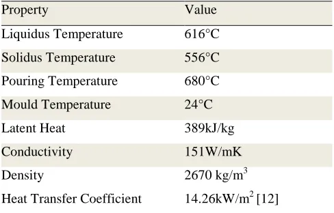
TABLE 1. - Boundary conditions and thermo-physical
properties of A356 used in the simulations.
Property Value
Liquidus Temperature 616°C
Solidus Temperature 556°C
Pouring Temperature 680°C
Mould Temperature 24°C
Latent Heat 389kJ/kg
Conductivity 151W/mK
Density 2670 kg/m3
Heat Transfer Coefficient 14.26kW/m2 [12]
Experimental
A 1kg aluminium A356 ingot was placed in a graphite
crucible and was heated to a temperature 720°C using
induction furnace. Once the desired temperature of the melt
was obtained, it was poured into a cylindrical copper mould
of 1 mm wall thickness, 25 mm in diameter, and 75 mm in
height.
The different pouring temperatures were set at 630°C,
650°C, 665°C and 680°C. After pouring, the molten metal
was held in the mould for 45s or 60s, at semi-solid
temperatures, before quenched into room temperature water.
A billet with pouring temperature of 665°C was also
[image:4.612.306.550.243.399.2]________________
[image:5.612.46.287.53.207.2]* Author to whom correspondence should be addressed. [email protected]
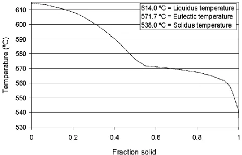
FIGURE 1. - A fraction solid vs temperature curve for A356
at a cooling rate 0.6°C/s [13].
The semi-solid temperature range of A356 alloy is
quoted with different solidus and liquidus temperatures
depending on the source of reference. In one previous work
this range was reported as 538°C to 614°C. Figure 1 shows
the fraction solid vs temperature curve of A356 at 0.6°C/s
cooling rate [13]. This fraction solid curve was used to
estimate the amount of solid before quenching.
The samples were sectioned 5 mm from the bottom of
the cast billets and mounted in Bakelite and microstructure
analysis was performed by optical microscope after etching
the surface of the polished moulded samples with Keller’s
reagent. A Reichert light optical inverted microscope with
Me F2 universal camera connected to a PC was used for
image capture. Microstructures were examined with Buhler
Omnimet Enterprise software.
RESULTS AND DISCUSSION
Simulation Results
The temperature profile within the billet from 2.5s to 61
s after pouring is shown in Figure 2. The simulation results
show that the mould was fully filled with molten metal 2.5s
after pouring, see Figure 2 (a). In the initial solidification
stage, the temperature started to drop first in the lower
region of the mould as shown in Figure 2 (b).
In the simulation, when the pouring process completed,
the bottom part showed lower temperature than the upper
part of the mould. This is may be due to the fact that the
bottom part of the mould is farthest away from the hot metal
that just transferred from the crucible and also has a longer
period of time in contact with the mould walls compared to
the melt within the upper regions of the mould.
This temperature difference between the top and bottom
regions became evident after 21s pouring time (Figure 2
(c)). The effects of pouring temperature on heat distribution
were also observed by other in previous work [14].
The temperature continued to drop until 61s with a drop
rate of 3°C/s in the simulation and the average temperature
drop during the previous experimental findings was 1°C/s
[12]. This is come to the agreement that the simulation
results were close to the previous experimental result,
sup-porting the accuracy of simulation result.
From the simulation, after 45s and 60s, the temperatures
were approximately 638°C and 622°C respectively. The
equivalent recorded temperatures from the experimental
work conducted were 635°C and 620°C at 45s and 60s
respectively. By correlating with Figure 1, these results
could then be used to estimate the fractions solid of the
billets before quenching.
In direct thermal method, the temperature cycle was
in-fluenced by the material and wall thickness of the mould
[12]. The temperature drops within a copper were higher
than a steel mould as steel has the higher volumetric heat
capacity. Furthermore, the greater selection of a wall
thickness is needed for a steel mould.
Experimental Results
Effects of Pouring Temperature
The billet produced with 665°C pouring temperature and
with natural solidification to room temperature produced a
dendritic microstructure, see Figure 3, as would be expected
under this conventional type of solidification. Even though
a controlled period for holding within the semi-solid
temperature region, a ripened type of dendritic
microstructure was produced. The microstructure of the
billets with different pouring temperatures and holding times
are presented in Figure 4 and Figure 5. The lower pouring
temperatures would be expected to have a significant effect
not just for the finer grain size but also the morphology of
the grain [11]. As per previous findings, the lower pouring
temperatures were found to produce more globular and finer
microstructures [15]. The primary phase microstructures
were also found within this work to be more spherical when
produced at lower pouring temperatures as shown in Figure
4 (a).
Lower pouring temperatures lead to higher cooling rates
from above the liquidus to below the liquidus as less
superheat has to be extracted. Furthermore, when the
cooling rate is higher, the undercooling of the alloy becomes
larger. A raise in undercooling increases the amount of
nucleation which ultimately results in a smaller grain size
from this larger crystallization driving force [16].
time : 2.5s time : 11s time : 21s time : 31s
[image:6.612.49.542.259.616.2]time : 41s time : 51s time : 61s
FIGURE 2. - Temperature distributions within aluminium billet from (a) 2.5s to (g) 61s after pouring.
680.0°C 671.7°C 663.5°C 655.2°C 646.9°C 638.7°C 630.4°C 622.1°C 613.9°C 605.6°C
597.3°C 589.1°C 580.8°C 572.5°C 564.3°C 556.0°C
(a)
(b)
(c)
(d)
________________
* Author to whom correspondence should be addressed. [email protected]
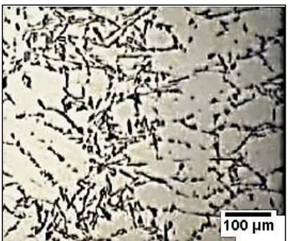
FIGURE 3. - Dendritic microstructure formed within billet
after solidification from pouring temperature of 665°C under
air cooling.
Effects of Holding Time
The role of holding time was to ensure an adequate
fraction solid before quenching. A longer holding time for a
specific constant pouring temperature produced larger
primary phase grains. Figure 5 shows the microstructures for
the samples produced with 630°C, 650°C and 680°C
pouring temperatures and with 60s holding time. These have
larger grain sizes compared with the microstructures of the
samples shown in Figure 4 produced with 45s holding time.
Formation of globular microstructure was influenced by
fraction solid [17]. The sample with a 630°C pouring
temperature was quenched at 570°C, equivalent to 0.65
fraction solid. The corresponding microstructure is shown in
Figure 5 (a). For the sample with 650°C pouring
temperature, with microstructure shown in Figure 5 (b), was
quenched at 590°C (0.4 fraction solid). The microstructure
was less globular compare with the sample produced with a
pouring temperature of 630°C. This was confirms that size
of primary grains was affected with a low fraction solid used
[17].
The sample with 680°C pouring temperature was
quenched at 620°C (Figure 5 (c)). This sample was therefore
still in the liquid condition upon quenching. The
microstructure results from this sample showed a primary
phase which was too large and irregular compared to what
would typically be required for semi-solid metal forming.
In order to understand the relationship between pouring
temperature and viscosity, the microstructure of the
respective billets should be related to the material fluidity.
Viscosity is an important indicator of the material capability
to fill the die cavity during casting. Lower viscosity
produced better movement of the material and allows the
semi-solid metal to move into the complex geometries such
[image:7.612.59.263.73.243.2]as thin die cavity sections.
FIGURE 4. - Microstructures from a 45s holding time and with pouring temperatures of (a) 630°C, (b) 650°C and (c) 680°C.
[image:7.612.57.550.526.670.2]________________
FIGURE 5. - Microstructures from a 60s holding time and with pouring temperatures of (a) 630°C, (b) 650°C and (c) 680°C.
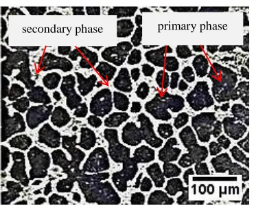
The two important phases in the microstructure of A356
are the primary aluminium phase which solidifies first and
the secondary aluminium-silicon phase which solidifies
second, shown in Figure 6. In general, a microstructure with
more globular primary grains and more liquid phase, seen as
secondary upon solidification, will have higher fluidity.
FIGURE 6. - Microstructure of the sample produced with a
45s holding time and a pouring temperature of 630°C.
Pouring temperature is one of the important parameters
that affect the evolution of the primary phase during
solidification [18]. Low pouring temperature is a key factor
that establishes higher temperature gradients within the
semi-solid metal which encourage the formation of a
multitude of nuclei and subsequently a more globular
microstructure upon holding within the semi-solid state.
Relationship between the pouring temperature and
microstructure formation is determined by the under cooling
temperature. The undercooling is the difference between the
equilibrium temperature and temperature which the material
cools, before the start of solidification [19]. The
undercooling is influenced by the solidification rates which
depend on the type of a mould material, mould thickness
etc. The formation of a microstructure which evolves within
material depends on the degree of undercooling.
During solidification process, as the undercooling
temperature and time increase, the melt potential nucleation
decreases resulting in a coarse-grained structure
deformation. Higher cooling rate is therefore associated with
a finer grain size and a globular microstructure. The higher
pouring temperature lead to a higher cooling rate as it need
more time to cool from the liquidus to solidus temperature.
For this reason, dendritic microstructure occurs.
The formation of a globular microstructure in these
experiments was influenced by the volume fraction of solid.
In semi-solid metal processing, the volume of the
fraction solid play the important rules in determined the
successful of the process. The fraction solid which is used in
semi-solid processing is normally in the range of 0.30 to 0.7
depending on the type of the material used [20]. During
rapid solidification, the nuclei start to deform from the
liquid condition. The nuclei evolved and impinged to each
other within the material and later produced a dendritic
primary phase secondary phase
[image:8.612.84.269.360.510.2]________________
* Author to whom correspondence should be addressed. [email protected]
microstructure as in typical solidification process. During
this process (from the liquid to dendritic microstructure
formation), the fraction solid which occurs inside the
material is increase as it approaching the solidus
temperature. The formation of the nuclei which is small at
this stage, become larger due to the increment of fraction
solid volume. The quenching technique which was applied
in this period, captured a finer globular shape
microstructure. For this reason, the proper selection of a
holding time in direct thermal method is crucial to allow the
formation of a desire microstructure feature due to the
fraction solid effect.
CONCLUSION
The simulation of the heat distribution inside the billet
and direct thermal method experiment was successfully
carried out. The simulation provided useful information
about solidification temperature and time prediction before
quenching. The copper mould was only fully filled 2.5s after
pouring. The A356 billet temperature decreased at
approximately 1°C/s from the initial pouring temperature.
The experimental work showed a fine spherical
microstructure can be achieved with the correct selection of
pouring temperature and holding time. A lower pouring
temperature contained more primary particles which were
also more globular than those formed from higher pouring
temperatures. The spherical microstructures were dominant
at the lower pouring temperature (630°C) regardless the
holding time either 60s or 45s. The longer holding time
produced larger primary phase particles which were also
less globular. The results of this work showed that the best
pouring temperature and time for the A356 alloy were at
630°C and 45s respectively. In d
irect thermal method
, the combination of proper pouring temperature and holding timeare necessary in order to produce the microstructure
required for semi-solid metal forming.
ACKNOWLEDGMENTS
The authors would also like to acknowledge the support
from the Ministry of Higher Education, Malaysia and
Dublin City University for funding this work.
REFERENCES
1. Brabazon D.; Browne D.J.; Carr A.J. Mechanical stir
casting of aluminium alloys from the mushy state:
Process, microstructure and mechanical properties.
Materials Science and Engineering A. 2002;
A326370-381.
2. Aqida S.; Maurel M.; Brabazon D.; Rosso M. Thermal
stability of laser treated die material for semi-solid metal
forming. International Journal of Material Forming.
2009; 2(0), pp. 761-764.
3. Spencer D.B.; Mehrabian R.; Flemings M.C.
Rheological behaviour of sn-15 pct pb in the
crystallization range. Metallurgical Transactions. 1972;
31925-1932.
4. Bo Chao Liao; Young Koo Park; Hong Sheng Ding.
Effects of rheocasting and heat treatment on
microstructure and mechanical properties of A356 alloy.
Materials Science and Engineering A. 2011; 528(3):
986-995.
5. Tebib M.; Morin J.B.; Chen X.G. Semi-solid processing
of hypereutectic A390 alloys using novel rheoforming
process. Transactions of Nonferrous Metals Society of
China. 2010; 201743-1748.
6. Bo X; Yuan Dong L; Ying M; Yuan H; Apelian D.
Commercial AM60 alloy for semisolid processing
Effects of continuous rheoconversion process on
micro-structure. Transactions of Nonferrous Metals Society of
China. 2010; 20s723-s728.
7. Guo H; Yang X; Wang J; Hu B; Zhu G. Effects of
rheoforming on microstructures and mechanical
properties of 7075 wrought aluminium alloy.
Transactions of Nonferrous Metals Society of China.
________________
8. Hussey M.J; Browne D.J.; Brabazon D.; Car A.J. A
direct thermal method of attaining globular morphology
in the primary phase of alloys in Proceedings of the 7th
International Conference on Semi-Solid Processing of
Alloys and Composites. 2002.pp. 575-580.
9. Jiaqi W.; Paixian F.; Hongwei L.; Dianzhing L; and Yiyi
L.; Shrinkage porosity criteria and opimized design of a
100-ton 30Cr2Ni4MoV forging ingot. Materials and
Design. 2012; 35446-456.
10.Ning Z.L.; Wang H.; Sun J.F. Deformation behavior of
semisolid A356 alloy prepared by low temperature
pouring. Materials and Manufacturing Processes. 2010;
(25): 648-653.
11. Hongwei W.; Boa L.; Jinchuan J.; Zunjie W. Influence
of thermal rate treatment and low temperature pouring
on microstructure and tensile properties of AlSi7Mg
alloy. Materials and Design. 2011; 322992-2996.
12.Carr A.J.; Browne D.J.; Hussey M.J.; Lumsden N.;
Scanlan M. Modelling and experimental development of
the direct thermal method of rheocasting. International
Journal of Cast Metals Research. 2007; 20(6): 325-332.
13.Brabazon D.; Brawne D.; Carr A.J. Processing and
properties of rheocast alloys. UCD PhD's Thesis. 2001.
14.Bouchard D.; Colbert J.; Pineau F.; Laplume F.; Hamel
F.G. Characterization of contact heat transfer
coefficients and mathematical modelling of a semi-solid
aluminium die casting in Proceedings of the 8th
International Conference on Semi-Solid Processing of
Alloys and Composites S2P, 2004, Limassol, Cyprus.
15.Fan C.H.;Chen Z.H.; He W.Q.; Chen J.H.; Chen D.
Effects of the casting temperature on microstructure and
mechanical properties of the squeeze cast al-zn-mg-cu
alloy. Journal of Alloys and Compounds. 2010;
504L42-L45.
16.Jun Wang; Shuxian He; Baode Sun; Qixin Guo;
Mitsuhiro Nishio. Grain refinement of Al–Si alloy
(A356) by melt thermal treatment. Journal of Materials
Processing Technology 2003, 141(1): 29-34.
17.Haga T.; Kapranos P. Simple rheocasting processes.
Journal of Materials Processing Technology. 2002,
130-131, 594-598.
18.Gencalp S.; Saklakoglu N. Semisolid microstructure
evolution during cooling slope casting under vibration of
A380 aluminum alloy. Materials and Manufacturing
Procesess. 2010, 25(9), 943-947.
19.Gowri S.; Samuel F.H. Effect of cooling rate on the
so-lidification behaviour of Al-7 Pct Si-SiCp metal matrix
composites. Metallurgical Transaction A. 1992, 23A,
3369- 3376.
20.Chayong S.; Atkinson H.V.; Kapranos P. Thixoforming
7075 aluminium alloys. Materials Science and