International Journal of Innovative Technology and Exploring Engineering (IJITEE) ISSN: 2278-3075, Volume-8 Issue-8S2, June 2019
Abstract ADAS applications using optical camera should have accurate view orientation for correct computation. We need calibration of view orientation which is changed from initial installed status for impact, deformation, etc. In this research, we proposed automatic computation methods for camera orientation with using optical flow captured movie and vehicle motion data without longtime task at a vehicle workshop. We used small set captured images for about 4seconds without correction for lens distortion and collected vectors of optical flow. Collected vectors of optical flow modified by using camera lens intrinsic in formation and using mathematical regression we calculated camera calibration data. We eliminated part of vectors of optical flows far from regression curve for we considered them as outlier data. We implemented using OpenCV API, made cases using equipment of 3degree of freedom camera motion control and tested on our implementation. We found that we can get camera orientation parameters, with accuracy range less than 5 pixels. Part of this error may come from initial configuration error and computation error. Therefore, fine tuning of calibration may be required after our proposed method however, fine tuning process can be more efficient with using calculated result from our method. Our experimental results show proposed method are fulfilled for fast detection of camera calibration data in ADAS application like 360 around view system with reasonable accuracy, performance. Furthermore, method for exclude outlier data work efficiently.
Keywords: Optical flow, Camera calibration, ADAS, Around view, Camera Transform
I.INTRODUCTION
Advanced Driver Assistance System (ADAS) to visualize blind spot use optical cameras should have accurate view orientation for correct computation. There are various kind of methods to calculating camera pan, tilt and roll angle from image obtained from camera [1]. We can get various sensor data including motion speed, pinion angle, tilting and roll angles of vehicle body, etc. from operating vehicle. With using these sensing data, we can decide status of vehicle movement is appropriate condition for automatic camera calibration. We proposed calculate camera orientation change related to initial orientation and vehicle movement direction using captured movie in appropriate condition.
In our research, we proposed efficient method to calculate camera orientation related to vehicle movement which can be adaptable on ADAS applications. We also proposed effective
Revised Manuscript Received on May 22, 2019.
Hyunjun Kim Department of Software and Computer Engineering, Ajou University, Suwon, Rep. of Korea
Hwanyong Lee Department of Software and Computer Engineering, Ajou University, Suwon, Rep. of Korea, [email protected]
method to exclude outlier data which can be added even experimental data. We assumed that vehicle is moving straight forward direction by excluding other status with sensing data.
[image:1.595.329.529.321.432.2]General calibration of the ADAS application should be performed using calibration pads located at the designated physical position around the vehicle which is illustrated in Figure 1. This calibration method is inconvenient because it cannot be carried out by an individual and must be carried out by specialists in maintenance procedures. Efficient automatic calibration without any human intervention is still required in automotive application.
Figure 1. Example of calibration process Previous methods of camera calibration using optical flow are based on comparison of optical flow of images and camera movement which is similar to our approach. However, previous methods have limitation that reference straight lines should be parallel to camera movement like Figure 2 (A). Another method used known object shape and movement to calculate camera parameters for object tracking which is not applicable vehicle application. Some methods use special sensor devices like stereoscopic camera, lidar, etc. [2]
(A)
Calculating Camera Orientation using Optical
flow for ADAS Applications
(B)
Figure 2. Previous methods of optical flow calibration [3][4]
Equation (1)
II.PROPOSEDMETHOD
Our proposed method is using optical flow of the video which is captured at appropriate condition. Condition for pan and tilt calibration is forward (camera lens direction) motion and horizontal movement for vehicle side attached camera. Condition of motion can be detected with using sensor data of vehicle. Equation (1) is ideal optical flow (Ox, Oy) of forward (+z axis) direction movement, where field of view (Fov_h, Fov_v), pan (θy) tilt (θx) and roll (θz) angle.
2.1. Calculation procedure
We assumed that roll angle change is none. Procedure for calculating pan and tilt is as follows;
a.collect optical flow set (x, y, dx, dy) from captured movie
b.ifopticalflowsetistoomuchbiased(80%locatedatonequad rantoronehalf)thenre-captureimages.
c.compute x intercepts and y intercepts of (x, dx) and (y, dy) pair with linear least squares method. This point is motion center (cx, cy). If correlation coefficient is less than 0.7 then back to step a.
d.compute pixel displacement between initial center (cx-ox, cy-oy) and compute pan (θy) and tilt (θx) with using camera field of view(Fov_h, Fov_v) and resolution.
2.2. Implementation
We implemented andtested to calculate camera parameters with the procedure which is stated above.
2.2.1. Test environment
[image:2.595.65.534.54.261.2]We developed test equipment to make test data for calculating camera orientation, pan and tilt using optical flow. We used GoPro HERO6 camera to take sample movie with various kind camera settings for instance, wide angle, linear angle mode, multiple frames per second. We selected configuration listed in Table 1 after various testing. We used 3 degree of freedom camera control system (Figure 3) to emulate pan, tilt and straight motion.
Table 1: Imaging equipment
Frame size 1080p (1920 × 1080)
Frame per second 24 FPS
Recording time 1 sec stop, 3 sec slide, 1 sec stop
Figure 3. 3DOF – Pan, Tilt, Slide controller
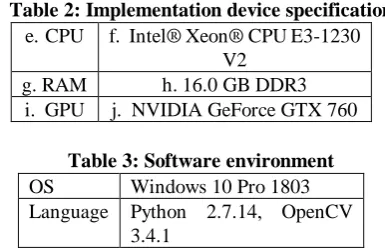
[image:2.595.338.524.231.361.2]Sample movie has been taken for 5 seconds with 50 cm straight movement with pan and tile configuration of about 10 degrees change. We implemented on PC environment specification listed on Table 2 and software environment is listed on Table 3.
Table 2: Implementation device specification
e.CPU f. Intel® Xeon® CPU E3-1230 V2
g.RAM h.16.0 GB DDR3
i. GPU j. NVIDIA GeForce GTX 760
Table 3: Software environment
OS Windows 10 Pro 1803
Language Python 2.7.14, OpenCV
3.4.1
We used OpenCV[5][6] application programming interface for captured image import, image pre-processing, optical flow calculation with Python language binding. We used Python language to use pandas, pyplot analyzing tool.
2.2.2. Intrinsic Camera parameter
[image:2.595.331.524.458.583.2]International Journal of Innovative Technology and Exploring Engineering (IJITEE) ISSN: 2278-3075, Volume-8 Issue-8S2, June 2019
Table 4: HERO6 Black Field of View (FOV) Information
Angle of view V.FOV deg H.FOV deg
16 x 9 W (zoom=0%) 69.5 118.2
16 x 9 W (zoom=100%) 35.7 62.2
16 x 9 Linear
(Zoom=0%)
55.2 85.5
16:9 Linear
(Zoom=100%)
29.3 49.8
2.2.3. Selection of optical flow method
[image:3.595.54.283.67.164.2]Optical flow is calculated from two image difference with time difference which generate vectors of motion in specific point. We tested with Lucas-Kanade method[7] and Farneback Method[8].
Figure 4.Lucas-Kanade method applied video
Figure 5. Pyramid Lucas-Kanade method applied video
The Lucas-kanade method[7] used in Figure 4 belongs to sparse optical flow and traces feature points using prominent feature points such as corners. This method can set the number of feature points to be traced and has a merit that calculation can be done in a short time because the amount of computation is small. However, the flow cannot be calculated for large movements exceeding the window size set as the movement of the car. As a result, the outliers also increased as a result of the small flow not related to the overall motion. To solve these problems, Pyramid Lucas-Kanade method, which searches various scaled images through a pyramid window, was applied and the same result as Figure 5 was obtained.
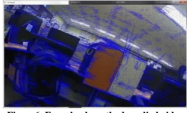
Figure6. Farneback method applied video
The second optical flow algorithm as shown in Figure 6 is the Farneback algorithm. It is not a method of tracking feature points but a method of obtaining optical flow of pixels at a specific position, so it is possible to obtain highly accurate results. However, since the calculation process is complicated, the amount of calculation and number of outliers is also relatively huge. The disadvantage of this method is that an average of 5 minutes is spent on an intel i7 CPU when analyzing a 5 second image with 1920x1080 resolution.
We applied the two algorithms and found that Pyramid Lucas-Kanade method is more suitable for camera auto calibration. In this paper, we will solve the problem by applying this algorithm.
2.2.4. Optical flow Analysis
ADAS, which is the scope of this paper, has four cameras on the front, left side, right side and rear side. However, since front and rear cameras and left and right cameras have the same application method, the front and left sides will be described like general ADAS application. [9]
In the case of the front camera, the camera parameters are searched from the vanishing of the feature points.
Figure 7. Front side camera optical flow calculation
[image:3.595.73.277.266.385.2] [image:3.595.71.276.413.534.2]Figure 8. Front side camera optical flow plotting
In Figure 8, start points andend points of the average movement in optical flows during the frame flow of camera moves are plotted by adding lines connecting these two points.
[image:4.595.319.541.250.574.2]The side camera has the same method as the front camera, but the vanishing point of the feature points exists outside the image frame.
Figure 9. Left side camera optical flow calculation
[image:4.595.65.283.286.407.2]When the optical flow of the feature points extracted from the left side camera image is displayed on the image frame, the result is Figure 9.
Figure 10. Left side camera optical flow plotting
Figure 10 is a graph showing the lines connecting the start and end points of the average movement in the optical flow of the left side camera image.In the case of the left side camera, since the vanishing point of the feature points exists outside the frame, the arbitrary extension line is drawn as a blue line.
III.RESULTSANDDISCUSSION
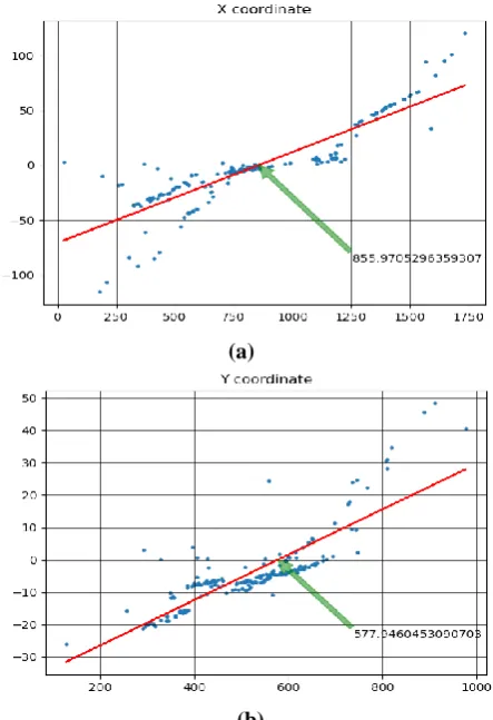
Optical flow data is gathered with OpenCV and tracing module and selection module is added. Image is captured with robot motion devices which already have alignment error less than 2 degrees. To obtain the optical flow set to be used in Equation (1), we need to find dx and dy in each camera, which can be obtained based on the vanishing point of the feature points.
The coordinates of the vanishing point of the feature points flow obtained by regression [10]. By comparing this coordinate with the θ value of the calibrated camera should have and calculate degrees the camera should correctly calibrated. Figure 11 illustrates calculating vanishing point by regression with x,y position and optical flow vector.
(a)
(b)
Figure 11. Regression of optical flow vector
[image:4.595.73.280.488.588.2]International Journal of Innovative Technology and Exploring Engineering (IJITEE) ISSN: 2278-3075, Volume-8 Issue-8S2, June 2019
Table5: Experiment result
Data Front camera
Tilt 0°, pan 0°
Front camera Tilt -10°, pan 0°
Front Camera Tilt -20°, pan 0°
Left Camera Tilt 0°, pan -10°
Left Camera Tilt -20°, pan 0° Tilt (in)
Tilt (out) Error
Pan (in) Pan (out)
Error
0° 2.09° 2.09°
0° 3.51° 3.51°
-10° -12.33°
2.33°
0° 4.02° 4.02°
-20° -23.88°
3.88°
0° 3.27° 3.27°
0° 1.21° 1.21°
-10° -13.99°
3.99°
-20° -21.53°
1.53°
0° 0° 0°
IV.CONCLUSION
We proposed efficient calibration methods with optical flow computation and estimation of camera orientation angle with reasonable accuracy. Our method use captured about 5 seconds movie, calculate optical flow with pyramid lucas-kanade method, calculate vanishing point from regression of x,y coordinate and optical flow. With using vanishing point and camera parameters, compute camera orientation changing. It may be required additional fine tuning to get more accurate result, however it worthy to be used in ADAS application like 360 view system camera adjustment. Total computation overhead to process proposed method are less than 0.5 seconds in PC environment. It is possible to adapt for adjustment of vehicle application.
ACKNOWLEDGMENT
This research was supported by the MIST (Ministry of Science and ICT), Korea, under the National Program for Excellence in SW supervised by the IITP (Institute for Information & communications Technology Promotion) (2015-0-00908).
REFERENCES
1. 1. Maybank S, Faugeras O. A theory of self-calibration of a moving camera. International Journal of Computer Vision.1992;8(2):123-151. 2. Brooks MJ, Chojnacki W, Baumela L. Determining the egomotion of an
uncalibrated camera from instantaneous optical flow. Journal of the Optical Society of America A. 1997Jan;14(10):2670.
3. Tapia E, Rojas R. A Note on Calibration of Video Cameras for Autonomous Vehicles with Optical Flow [Internet]. Freie University Berlin; 2013 [cited 2018Oct28]. Available from: http://www.mi.fu-berlin.de/inf/groups/ag-ki/publications/B-13-02/TR-Ern esto.pdf
4. Kanatini KI. Transformation of Optical Flow by Camera Rotation. IEEE Tr. on PAMI. 1988;10(2):131-143.
5. OpenCV: Optical Flow. [cited 28 October 2018]. Available from: https://docs.opencv.org/ 3.3.1/d7/d8b/tutorial_py_lucas_kanade.html 6. Motion Analysis and Object Tracking [Internet]. 2018 [cited 28 October
2018]. Available from:
https://docs.opencv.org/3.0-beta/modules/video/doc/ motion_analysis_and_object_tracking.htm
7. Geistert J, Senst T, Sikora T. Robust local optical flow: Dense motion vector field interpolation. 2016 Picture Coding Symposium (PCS). 2016;:1–5.
8. Farneback G. Fast and accurate motion estimation using orientation tensors and parametric motion models. Proceedings 15th International Conference on Pattern Recognition ICPR-2000.
9. Baftiu I, Pajaziti A, Cheok KC. Multi-mode surround view for ADAS vehicles. 2016 IEEE International Symposium on Robotics and Intelligent Sensors (IRIS). 2016;