Abstract: The paper proposes a 3- Ph 3- wire Modified Shunt active line conditioner (MSALC) incorporating the features of notch adaptive filter for non-sinusoidal PCC voltages. The theory behind the design of MSALC is instantaneous power theory for the excellent compensation characteristics. Notch Adaptive Filter (NAF) employed with its principal features to handle the unbalanced as well as distorted PCC voltages. Using Notch adaptive filter significant with MSALC is tested from the simulation results of Matlab/SimPower System tool environment by injecting anti-harmonic current of loads even though under non-sinusoidal voltage conditions.
Index Terms: Point of Common Coupled, Modified Shunt Active Line Conditioner, Notch Adaptive Filter, Instantaneous Power theory.
I. INTRODUCTION
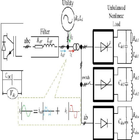
Due to the high proliferation of non-linear loads on the customer side distribution system, a sufficient quantity of non-sinusoidal component current as being compensated into power distribution systems. Many types of research are being proposed starting from the passive LC filter in the earlier 1990s [1]. But active power line conditioners employing active power filter has found to provide even desirable performance to remove harmonic currents [1]-[43]. The objective of the proposal is harmonic-free utility current even though under unbalanced as well as distorted load conditions. Fig. 1 shows the global structure and compensation characteristic of Modified Shunt Active Line Conditioner (MSALC). Section 3 details each component of the distribution system with MSALC used in this proposal. Summarize of earlier presented approaches reveals that the instantaneous power theory proved to be the significant one due to its control and design feature under balanced as well as during distorted condition as proposed by H. Akagi [1], [27]. The theory as proposed by H. Akagi fails to perform well to remove harmonics in the distribution system during unbalanced load current or under distorted source voltage condition [5], [7], [19], [27]. Point of commonly coupled control is a necessity for grid voltage measurement [3], [5], [7], [27]. But, non-ideal voltage condition may also prevail due to changes in the load impedance over that time which in
Revised Manuscript Received on May 06, 2019
Mr. G.Muralikrishnan B.E degree in EEE from Thangavelu Engineering College, Chennai, Affiliated to Annna University and M.E degree in Power System Engineering from College of Engineering, Guindy, Anna University in 2009 and 2012 respectively.
[image:1.595.312.547.379.614.2]turn leads to unbalanced load characteristics arising from the various phase currents of the load. Therefore, the dynamic characteristics of the electrical load also need to be considered for the desired compensation current. Earlier researches provided solutions to this problem only by assuming the source to be a balanced source such that the controller dynamic for a perturbation is better responsive [10], [22]. Also, the previous research methodology does not verify for various load conditions [19]. Some research proposals employed the dq-coordinate and LPF for injecting an anti-harmonic current that needs reference frame transformation which makes the controller design more complex and complicated too [19].
Fig. 1. Global structural block diagram of SALC
Artificial intelligence based solutions were implemented for the control of SALC performing even though the voltages are non-ideal [2]. Hysteresis band current control and Sliding-mode control are other control schemes for the control of SALC respectively [20], [37]. Applying Self-tuning filter (STF) is another vital control approach to solve the problems of SALC under non-ideal voltage condition termed as STF-pq theory and STF-dq theory [9], [16].
Performance Analysis of Modified Shunt Active
Line Conditioner (MSALC) Using Notch
Adaptive Filter
Performance Analysis of Modified Shunt Active Line Conditioner (MSALC) Using Notch Adaptive Filter
Above mentioned control approach has considered the 3-phase 3-wire SALC and requires a phase locked loop for STF implementation. So, Notch adaptive filter (NAF) which is a critical signal processing unit need to be employed to evaluate the positive-sequence component from a non-sinusoidal signal that justifies its excellent characteristic response compared with LPF and HPF [23]. The idea behind NAF is like that of PLL. But, NAF indirectly evaluates the target signal in terms of entry signal whereas PLL evaluates the target signal directly [29]. NAF does not require VCO as required by PLL and is not sensitive to power system disturbances such as harmonics. NAF takes in to account the frequency deviation which is needed to properly evaluate the specified sine component of the voltage waveform [29].
Powerful signal processing approaches were proposed earlier [11]. Out of these approaches, FFT and DFT are very familiar. Precisely, NAF is applied for non-linear loads to compensate for harmonic components [30]. An enhanced NAF need to have a powerful signal processing unit which can discriminate the sequence components as required for injecting the anti-harmonic part from SALC. From the previous researches, it is clear that the objective of SALC is the requirement of a pure sinusoidal source current controlling scheme rather than a fixed source instantaneous power [26].
Moreover, it is not possible to apply two control schemes instantaneously with harmonic distorted supply voltage. So, primarily NAF is employed to regulate a 3-Ph 3-W SALC in ABC-coordinate where filtering methods for the separation of fundamental and non-linear components are inessential. Secondarily, the system is executed and verified with unbalanced, non-linear and variable load conditions under distorted or unbalanced supply voltages. The enhanced conditioner unified NAF features with SALC termed as MSALC which is viable under various testing conditions. MSALC does not require any complex algorithm that provides compensation of harmonics, wattless power and unequal currents for non-sinusoidal unbalanced load.
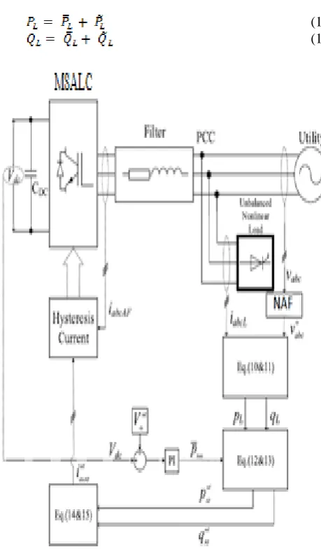
Hence, this paper confers the research task that is capable of providing perfect DC voltage regulation by reducing the current tracking error for accurate current harmonic elimination all power quality perturbations. By employing the adaptive notch filter, MSALC is capable of handling all the power perturbations under various conditions such as steady state and dynamic state [3]-[8]. To elaborate in detail about the research work, Section 2 of this paper deals with control theory and pre-processing unit for MSALC which includes the realization of notch adaptive filter using sub-filters and evaluation of the condenser design parameters and procedures involved in the control of condenser. Simulation of the distribution system without MSALC and with MSALC for different loads such as with RL load and with RLC load for distorted and unbalanced conditions are carried out and its outcomes are briefed in Section 3. Finally, Section 4 concludes the inference from the outcomes of the research work that the THD of the source current is reduced to 3.90% from 12.12% for RL load and to 3.59% from 12.24% for RLC load using notch adaptive filter based MSALC. The HCRF of this MSALC is found to be 32.178% for RL load under dynamic condition and 29.33% for RLC load under dynamic condition which is lesser value than
other SALC reported yet analyzed using FFT Analysis [12]-[15], [17],[18], [24]-[43].
II. MODIFIEDSHUNTACTIVELINE CONDITIONER
The PWM inverter of the MSALC needs to provide the injection current as required by the load for maintaining the sinusoidal nature of the source current. Using instantaneous power theory, MSALC is pre-processed at the same time instant to model such each parameter of the system . DC condenser voltage, inverter output current, source voltage and load current respectively are the entry variables to the conditioner. As the utilization energy level is to be observed and controlled simultaneously so as derive the objective function of the load. The fundamental positive sequence component is evaluated from non-sinusoidal voltage sequentially and precisely using notch adaptive filter. So, the conditioner can accurately assess the major wattless power on the load side and also to deliver the significant wattless power can produce the fundamental positive sequence AC in quadrature with the significant positive sequence voltage. Mainly, for implementing the system more effective symmetrical component transformation is not adopted and employed for the control of MSALC.
A. MSALC as derived from Pre-processing unit and theory proposed by Akagi (NAF)
The theory as presented by Akagi is no longer feasible considering non-sinusoidal PCC potential and is possible only by using an ideal balanced 3-phase system[1], [27]. Also, under non-sinusoidal PCC potential, the aggregate of the αβ factors is a variable and real and reactive power at each instant has non-linear current and voltage components. Subsequently, SALC cannot develop restitution current to balance non-sinusoidal current that provides much load current harmonics above than that it requires. Finally, a powerful tool employing NAF is applied to remove PCC voltages. Consequently, evaluating the real and imaginary powers. The source non-sinusoidal potential is analyzed using NAF. The transient characteristic of NAF is expressed by using the differential equations as
(1)
(2)
(3)
Where γ and are controllable real positive variables, be the entry potential, be the differential signal, be the appropriate frequency for evaluating the accuracy and performance of the method in tracing the signal response. By controlling the design variables, comparative analysis between preciseness and speed of convergence is performed. need to be maximum for eliminating oscillatory nature; whereas should be enhanced to increase the
convergence speed. NAF has three integrators.
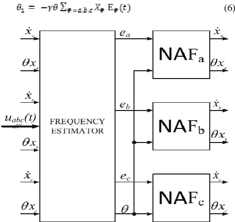
The 3-phase system is the ninth order system as each 1-phase NAF is of the third-order system as depicted in Fig. 2. Hence, there is no requirement of estimating the frequency of each phase independently as the 3-phase signal has the same frequency of ω. Also, the single operation of NAFs leads to tedious solid state practice and requires a higher degree of manipulations using simulation tools. To increase the convergence speed, 3-phase NAF is developed using the seventh-order system instead of the ninth order system as expressed by below equations, where is a function of frequency ω.
(4) (5)
To estimate ω, entry variables of all sub-filters for updated law of frequency estimation are required. Whereas entry variable and differential variable required for updating is expressed by
[image:3.595.297.545.231.568.2](6)
Fig.2. Block diagram of 3-Ph NAF realized using Sub-filters
Cyclic evaluator and exact block diagram realization of Φ sub-filter (NAFΦ) are derived using equations (4) – (6)
respectively. Convergence and precise evaluation of Ps-components for NAF during non-sinusoidal PCC potential are required. Positive sequence, negative sequence, and zero-sequence components are the entry variables of NAF is represented as
(7) (8) (9)
Where is the 3*3 identity matrix, and and are 3*3 matrices as given by the equations (10) and (11)
(10)
(11)
Fig. 3 depicts the synoptic representation for evaluating symmetrical components using precise transformation. The
3-Ph NAF processes the 3-phase signals , ,
and . Every phase first order component, its cyclic component and its quadrature phase difference from each sub-filter as obtained and employed for the calculation of the symmetrical components. Upon evaluating the fundamental components of potential, the theory as proposed by H. Akagi is applied for restituting non-linear loads. Real power ( ) and reactive power ( ) of the load at the instants are evaluated by Clarke transformation as expressed by the equations (12) and (13).
Fig. 3. Synoptic Diagram of Linear Transformation
(12)
(13)
[image:3.595.48.290.291.520.2]Performance Analysis of Modified Shunt Active Line Conditioner (MSALC) Using Notch Adaptive Filter
So, LPF is employed to compensate for the oscillatory component having corner frequencies within 20 to 100 Hz.
[image:4.595.46.276.78.474.2](14) (15)
Fig. 4. Controller flow diagram of MSALC
The mean value part from the first order constituents of the load current is derived. The oscillating part from the non-sinusoidal and negative sequence components is estimated. The source delivers only the mean value of power required by the load, while MSALC supplies the remaining reactive power and oscillating part. DC voltage controller controls the voltage of the DC condenser to be as constant. DC voltage control is performed by the PI controller, while LPF removes the transient harmonics present in the DC condenser. The base powers of ALC are expressed by
(16) (17)
The instruction currents in 3-phases are derived using reverse Clarke transformation as expressed by equations (18) and (19). Ultimately the computation is performed using the hysteresis current scheme. Fig. 4 gives the overall control methodology of MSALC for 3-phase 3-wire system.
(18)
(19)
B. Control of Condenser Voltage (Vdc) and Condenser
design parameters calculation
The power loss of the dc condenser by equation (20) expressed as
(20)
Where condenser voltage and current are represented as and respectively. Neglecting the internal resistance of the condenser, expressed as
(21)
Where C be the condenser capacitance. So, equation (20) expressed as
(22)
Considering the and to be as constant such that = 0. If is the variant from , then is given by
(23)
By taking Laplace transformation of equation (23), transfer
function of to is given by
(24)
Where Laplace transform of and are and
respectively. The Closed-loop transfer function of the system is given by equation (25).
(25)
C(s) be the controller transfer function as expressed by equation (26).
(26)
Where T is the time constant of 100 ms. As the voltage controller is of PI type, proportional gain as given by the expression
(27)
III. SIMULATION MODEL AND RESULTS
The simulation is carried out in two sections, first distribution system without MSALC having both RL and RLC load as shown in Fig. 5 and followed by it MSALC performance with the distribution system having both RL and RLC to handle the unbalanced and /or distorted PCC voltages. From Fig. 6 & Fig. 7, it is clear that source with non-linear RL load is connected up to 2.5 sec and at 2.5sec the source is connected with non-linear RLC load up to 5sec is distorted.
Fig. 5. Simulation Model without MSALC
[image:5.595.59.294.175.410.2]Fig. 6. Waveform of the Distorted Source Voltage
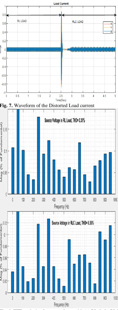
Fig. 7. Waveform of the Distorted Load current
Fig. 8. FFT analysis of source voltage with (a) RL & (b) RLC Load
[image:5.595.50.288.446.662.2]Performance Analysis of Modified Shunt Active Line Conditioner (MSALC) Using Notch Adaptive Filter
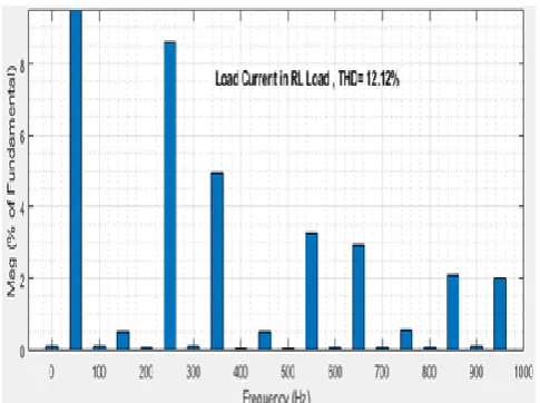
Fig. 9.(a) FFT analysis of load current with RL load
Fig. 9.(b) FFT analysis of load current with RLC load
[image:6.595.46.289.48.229.2] [image:6.595.308.547.48.365.2] [image:6.595.46.288.285.481.2]From the FFT analysis, as shown in Fig. 9, it is clear that load current is distorted for RL and RLC load with THD values of 12.12 % and 12.24% respectively as presented in Table. 1.
Table. 1. THD of the Parameters without MSALC
S.No. Parameter Type of Load
THD(% )
1.
Source Voltage RL Load 0.39
2. RLC Load 0.36
3. Load Current & Source Current
RL Load 12.12
[image:6.595.307.547.390.709.2]4. RLC Load 12.24
Fig. 10. Simulation Model with MSALC based on NAF Table. 2. Power Distribution System Circuit Parameters
Source Specifications
1. System Voltage (Vs) 415 Volts
2. System Frequency (fs) 50 Hz
Distribution Line values
3. Line Resistance (RLine) 0.1 Ω
4. Line Inductance (LLine) 0.5 mH
DC-link Parameters
5. Capacitor Voltage (Vdc) 100 volts
6. Capacitor Value (Cdc) 60 µF
VSI (Inverter) parameters
7. Output Voltage (Vo) 100 Volts
8. Output Frequency (fo) 50 Hz
Type of Thyristor Switches IGBT
9. On-State Resistance (Ron) 1mΩ
10. Snubber Resistance (Rs) 10 µΩ
Load Parameters (3Φ Diode Bridge Rectifier with 3Φ Unbalanced RL Load)
11. R-Phase Values (R-L load) 40 ohms, 18.85 H
12. Y-Phase Values (R-L load) 25 ohms, 12.57 H
13. B-Phase Values (R-L load) 10 Ohms, 50 H
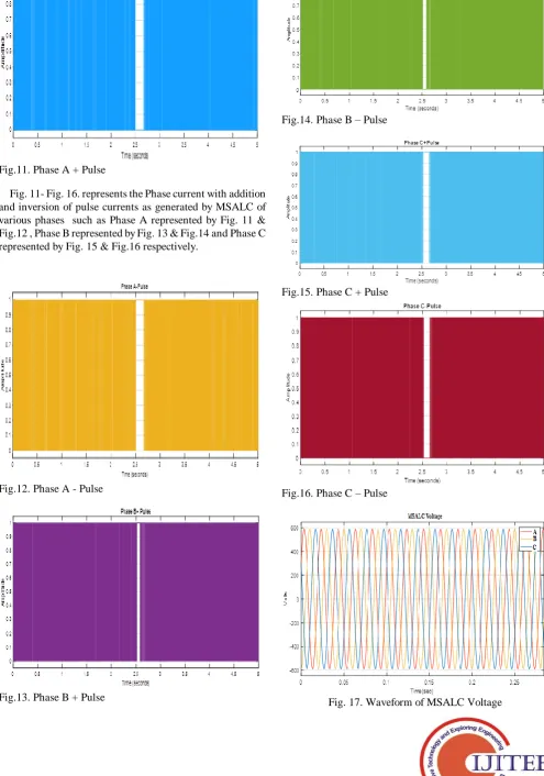
[image:6.595.307.547.393.705.2]Fig.11. Phase A + Pulse
[image:7.595.305.548.54.569.2]Fig. 11- Fig. 16. represents the Phase current with addition and inversion of pulse currents as generated by MSALC of various phases such as Phase A represented by Fig. 11 & Fig.12 , Phase B represented by Fig. 13 & Fig.14 and Phase C represented by Fig. 15 & Fig.16 respectively.
[image:7.595.48.544.93.799.2]Fig.12. Phase A - Pulse
Fig.13. Phase B + Pulse
Fig.14. Phase B – Pulse
Fig.15. Phase C + Pulse
Fig.16. Phase C – Pulse
[image:7.595.48.302.350.716.2]Performance Analysis of Modified Shunt Active Line Conditioner (MSALC) Using Notch Adaptive Filter
Fig. 18. Waveform of MSALC current
[image:8.595.306.546.96.293.2]From Fig. 17, it is clear that MSALC delivers the voltage which is found to be stiff, but from Fig. 18, it is clear that the MSALC injects anti-harmonic current.
Fig. 19. Waveform of source voltage with MSALC
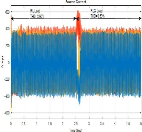
Fig.20. Waveform of the source current with MSALC
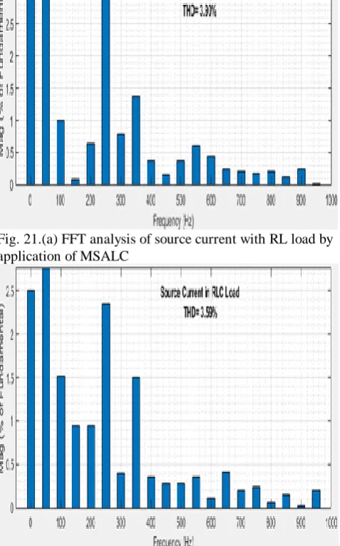
From the Fig. 19, it is clear that source voltage is undistorted by the application of MSALC and from Fig.20, it is understood that the source current is restored from the distorted load within a time duration of 100 ms. From the FFT analysis as depicted using Fig.21, the source current is distorted only with THD values of 3.90 % and 3.59% for RL
and RLC load respectively due to the application of the MSALC which is less than 5% as prescribed by the IEEE Std. 519 for harmonics level in the power distribution system.
Fig. 21.(a) FFT analysis of source current with RL load by application of MSALC
[image:8.595.307.546.136.519.2]Fig. 21.(b) FFT analysis of source current with RLC load by application of MSALC
[image:8.595.308.546.560.717.2]Fig.23. Waveform of Voltage for the unbalanced load with RL and RLC load
From Fig. 22, it is understandable that the voltage is found to be balanced and undistorted even with the unbalanced load by application of MSALC. From Fig.23, it is clear that the current is recovered from the unbalanced condition at the PCC within a period of 100 ms due to the application of MSALC.
Fig. 25. Source current with RL & RLC load during unbalanced condition by application of MSALC
From Fig.24, it is clear that load current with RL load and with RLC load has THD of 11.22% and 4.53% respectively. Fig.25, shows the source current with RL load and with RLC load has THD of 3.90% and 3.59% respectively due to the application of MSALC which is less than 5% as prescribed by the IEEE Std. 519 for harmonics level in the power distribution system.
Table. 3. THD of the Parameters with MSALC
S.No. Parameter Type of Load
THD (%)
1.
Source Voltage RL Load 0
2. RLC Load 0
3.
Source Current RL Load 3.90
4. RLC Load 3.59
5. Unbalanced
Load Current
RL Load 11.22
6. RLC Load 4.53
Harmonic Current Ratio Factor (HCRF) for RL Load =
= = 32.178%.
Harmonic Current Ratio Factor (HCRF) for RLC Load =
[image:9.595.305.544.64.286.2] [image:9.595.46.290.366.757.2]Performance Analysis of Modified Shunt Active Line Conditioner (MSALC) Using Notch Adaptive Filter
IV. CONCLUSION
The proposed3-phase 3-wire MSALC is implemented in 3 phase power distribution system using 3-phase NAF based control strategy. For various source and load conditions such as distorted PCC voltage and unbalanced load conditions, the performance evaluated for the proposed MSALC.
Through simulation employing Matlab/Simulink software, the propounded MSALC performance have been analyzed and validated. The simulation outcomes support the efficacy of the conditioner (MSALC) over traditional conditioners and filters for different load and supply instants. The dynamic characteristics of MSALC based on NAF accentuated by features such as excellent harmonic content restitution, the supply currents are harmonic-free and balanced and nearly in phase with supply voltage, maintenance of DC condenser voltage to its instruction value for all source and load conditions. Besides, the proposed MSALC retards the source current THD value too below 5% which is the benchmark as set by IEEE-519 standard for harmonic control level in the power distribution system. Moreover, in this research work the THD of the source current is reduced to 3.90% from 12.12% for RL load and to 3.59% from 12.24% for RLC load using notch adaptive filter based MSALC. The HCRF of this MSALC is found to be 32.178% for RL load under dynamic condition and 29.33% for RLC load under dynamic condition which is lesser value than other SALC reported yet analyzed using FFT Analysis [12]-[15], [17],[18], [24]-[43].
REFERENCES
1. H. Akagi, "New trends in active filter for power conditioning," IEEE Trans Ind Applications, Vol. 32, No. 6, (1996), pp. 1312-1322.
2. F. J. Alcantara, P. Salmeron, "A new technique for unbalancing current and voltage estimation with neural networks," IEEE Trans. on Power Systems. Vol. 20, No.2, (2005), pp. 852-858.
3. B.A. Angelico, L.B.G. Campanhol, S.A. Oliveira da Silva, , "PI/PID tuning procedure of a single phase shunt active power filter using bode diagram," IET Power Electron., Vol. 7, No.10, (2014), pp. 2647-2659. 4. K. Antoniewicz, M. Jasinski, M.P. Kazmierkowski, M. Malinowski,
"Model predictive control for three level four-leg flying capacitor converter operating as shunt active power filter," IEEE Trans. On Ind. Electron., Vol. 63, No.8, (2018), pp. 255-5262.
5. M. Aredes, E. H. Watanabe, E. V. Salgado, "Comparisons between the pq and pqr theories in three-phase four-wire systems," IEEE Trans. on Power Electronics. Vol. 24, No.4, (2009), pp. 924-933.
6. Bhim Singh, D. Sunil Kumar, A. Sabha Raj, "An improved Control Algorithm of DSTATCOM for Power Quality improvement," Electrical Power and Energy Systems, Vol.64, (2015), pp. 493-504.
7. S. Biricik, S. Redif, O.C. Ozerdem, S.K. Khadem, M. Basu, "Real time control of shunt active powerr filter under distorted grid voltage and unbalanced load condition using self-tuning filter," IET Power Electron., Vol. 7, No.7, (2014), pp. 1895-1905.
8. M. Bouzidi, A. Benaissa, S. Barkat, S. Bouafia, A. Bouzidi, "Virtual flux direct power control of the three-level NPC shunt active power filter based on back stepping control," Int. J. Syst. Assur Eng Manag., Vol. 8, No.2, (2017), pp. 287-300.
9. P. Chittora, A. Singh, M.Singh, "Application of self-tuning filter for power quality improvement in a three-phase-three-wire distorted grid system," IEEE Conf. ICPS 2017, (2017), pp. 313-318.
10. M. Depenbrock, V. Staudt, H. Wrede, "Concerning Instantaneous power compensation in three-phase systems by using p-q-r theory," IEEE Trans. On Power Electron..Vol. 19, No.4, ( 2004), pp. 1151-1152.
11. L. W. Dixon, J. C. Garcia, M. T. Luis, "A control system for three-phase active power filter which simultaneously compensates power factor and unbalanced loads," IECON 93. No.2, (1993), pp. 1083-1087.
12. P. Edris, F.A. Mudathir, M.M. Daniel, G.B. Oriol, C.T.C. Juan, " Hysteresis current control technique of VSI for compensation of grid connected unbalanced loads," Electric Engg, Vol. 96, (2014), pp. 27-35. 13. L. Feng, Y. Wang, "Modeling and Resonance control of modular three
level shunt active power filter," IEEE Trans. On Ind. Electron., Vol. 84, No.9, (2017), pp. 7478-7486.
14. L.B. Garcia Campanhol, S.A. Oliveira da Silva, A. Goedtel, " Application of shunt active power filter for harmonic reduction and reactive power compensation in three phase four wire systems," IET Power Electron., Vol. 7, No. 11, (2014), pp. 2825-2836.
15. J. He, Y.W. Li, F. Blaabjerg, X. Wang, "Active Harmonic filtering using Current-Controlled, Grid-Connected DG units with Closed-Loop Power Control," IET Power Electron., Vol. 29, No. 2, (2014), pp. 642-653. 16. K. Kamel, Z. Laid, K. Abdallah, K. Anissa, "Performance of shunt active
power filter using STF with PQ strategy in comparison with SOGI based SRF strategy under distorted grid voltage conditions," ICAIRES 2018, (2018), pp. 421-428.
17. P. Kanjiya, V. Khadkikar, H.H. Zeineldin, "Optimal control of shunt active power filter to meet IEE std. 519 current harmonic constraints under nonideal supply condition," IEEE Trans. on Ind. Electron., Vol. 62, No.2, (2015), pp. 724-734.
18. T.L. Lee, Y.C. Wang, J.C. Li, J.M. Guerrero, "Hybrid Active filter with variable conductance for harmonic resonance suppression in industrial power systems," IEEE Trans. on Ind. Electron., Vol. 62, No. 2, (2015), pp. 746-756.
19. H. Majid, M. Mustafa, Y. V. Ali, "RDFT based control of a 3-phase 4-leg SAPF under unbalanced load and non-ideal mains voltage conditions," IEEE Conf., 22nd ICEE 2014.
20. N. Mendalek,"Sliding-mode control of three-phase four wire shunt active power filter," 2008 Candian Conference on Electrical and Computer Engineering, (2008), pp. 443-448.
21. P. Mihaela, A. P . Cristina, D. Mircea, "Application of generalized instantaneous non-active power theories in the control of shunt active power line conditioners: practical evaluation under nonideal voltage and unbalanced load," Nonlinear dynamics of the electronic system. Vol. 438, (2014), pp. 125-133.
22. S. Mikkili, A. K. Panda, "RTDS hardware implementation and simulation of SHAF for mitigation of harmonics using p-q control strategy with PI and fuzzy logic controllers," Frontiers of Electrical and Electronics Engineering. Vol. 7, (2012), pp. 427-437.
23. M. Mojiri, M. K. Ghartemani, A. Bakhshai, "Time Domain Signal Analysis Using Adaptive Notch Filter," IEEETrans. Signal Processing. Vol. 55, No. 1, (2007), pp. 85-93.
24. J. Morales, L.G.D. Vicuna, R. Guzman, M. Castilla, J. Miret, "Modeling and Sliding mode control for three-phase active power filters using the vector operation technique," IEEE Trans. On Ind. Electron., Vol. 85, No. 9, (2018), pp. 6828-6838.
25. X. Mu, J. Wang, W. Wu, F. Blaabjerg, "A modified Multifrequency passivity based control for shunt active power filter with model parameter adaptive capability," IEEE Trans. on Ind. Electron., Vol. 66, No. 1, (2018), pp. 760-769.
26. T. Nguyen Duc, F. Goro, N. B. M. Mohd, "3-phase 4-wire Shunt APF under non-ideal PCC voltage using Adaptive Notch Filter," 2014 IEEE PES Conference, (2014), pp. 1-5.
27. F.Z. Peng, J.S. Lai, "Generalized instantaneous reactive power theory for three-phase power systems," IEEE Trans. Ins. and Meas. Vol. 45, No.1, (1996), pp. 293-297.
28. M. Qasim, V. Khadkikar, "Application of Artificial Neural Networks for Shunt Active Power Filter Control," IEEE Trans. Ind. Info., Vol. 10, No. 3, (2014), pp. 1765-1774.
29. H. A. Rivas, J. Bergas, "Frequency determination in a single-phase voltage signal using adaptive notch filters," ICEPQU 2007, pp. 1-7.
uthor-2 Photo
31. A. Sabha Raj, Bhim Singh, "Neural Network based conductance estimation control algorithm for shunt compensation," IEEE Trans. Ind. Info., Vol. 10, No. 1,( 2014), pp. 569-577.
32. W.R.N. Santos, E.R.C.D. Silva, C.B. Jacobina, E.D.M. Fernandes, A.C. Oliverira, et., al, "The transformerless single phase universal active power filter for harmonic and reactive power compensation," IEEE Trans. On Power Electron., Vol. 29, No. 7, (2014), pp. 3563-3572.
33. B. Singh, A. Chandta, K. Al-Haddad, "A review of active filters for power quality improvement," IEEE Trans. Ind. Electron, Vol. 46, No. 5, (1999), pp. 960-971.
34. K.C. Siddharthsingh, C. S. Mihir, T. Ram Ratan, P.N. Tekwani, "Analysis, design and digital implementation of a shunt active power filter with different schemes of reference current generation," IET Power Electron, Vol. 7, No.3, (2014), pp. 627-639.
35. G. Son, H.J., Kim, B.H. Cho," Improved Modulated carrier control with On-time Doubler for a Single-Phase Shunt Active Power Filter," IEEE Trans. on Power Electronics., Vol. 33, No. 2, (2018), pp. 1715-1723. 36. E.S. Sreeraj, E.K. Prejith, C. Kishore, B. Santanu, "An active harmonic
filter based on One- Cycle Control," IEEE Trans. On Ind. Electron., Vol. 61, No.8, (2014), pp. 3799-3809.
37. S. Swain, P.C. Panda, B.D. Sududhi, "Three Phase Shunt Active Power Filter using a new Weighted Adaptive Hysteresis band current controller," 2014 International Conference on Circuits, power and Computing Technologies, (2014), pp. 781-786.
38. K.H. Tan, F.J. Lin, J.H. Chen, "DC-link voltage regulation using RPFNN-AMF for three-phase Active power filter," IEEE Access, Vol. 6, (2018), pp. 37454-37463.
39. Y. Terriche, S. Golestan, J.M. Guerrero, D. Kerdoune, J.C. Vasquez, "Matrix Pencil Method- based reference current generation for shunt active power filters," IET Power Electron., Vol. 11, No. 4, (2018), pp. 772-780. 40. P. Thirumoorthi, N. Yadaiah, "Design of current source hybrid power filter for harmonic current compensation," Simulation modelling Practice and Theory, Vol. 52, (2015), pp. 78-91.
41. M. Torabian Esfahani, S.H. Hosseinian, B. Vahidi, "A new optimal approach for improvement of active power filter using FPSO for enhancing power quality," Electrical Power and Energy Systems, Vol. 69, (2015), pp. 188-199.
42. T. Wajahat Ullah, M. Saad, "Three-Phase Transformerless Shunt Active Power Filter with Reduced Switch Count for Harmonic Compensation in Grid-Connected Applications," IEEE Trans. on Power Electronics, Vol. 33, No. 6, (2018), pp. 4868-4881.
43. T. Wajahat Ullah, M. Saad, S. Mehdi, H. Ben, "Active power filter for mitigation of power quality issues in grid integration of wind and photovoltaic energy conversion system," Renewable and Sustainable energy reviews, Vol. 70, ( 2017), pp. 635-655.
AUTHORSPROFILE
Mr. G.Muralikrishnan, received his B.E degree in EEE from Thangavelu Engineering College, Chennai, Affiliated to Annna University and M.E degree in Power System Engineering from College of Engineering, Guindy, Anna University in 2009 and 2012 respectively. He is working towards his Doctoral of Philosophy in Power quality improvement using MSALC. His area of interest includes Power quality improvement using Custom power devices and using FACTS devices in power Distribution and transmission System. He is also a member in various technical societies such as IAENG.