InTrans Project Reports Institute for Transportation
10-2010
Identification of Practices, Design, Construction,
and Repair Using Trenchless Technology
Muhannad Suleiman
Iowa State University
Larry J. Stevens
Iowa State University
Charles T. Jahren
Iowa State University, [email protected]
Halil Ceylan
Iowa State University, [email protected]
William M. Conway
Iowa State University, [email protected]
Follow this and additional works at:http://lib.dr.iastate.edu/intrans_reports Part of theCivil and Environmental Engineering Commons
This Report is brought to you for free and open access by the Institute for Transportation at Iowa State University Digital Repository. It has been accepted for inclusion in InTrans Project Reports by an authorized administrator of Iowa State University Digital Repository. For more information, please [email protected].
Recommended Citation
Suleiman, Muhannad; Stevens, Larry J.; Jahren, Charles T.; Ceylan, Halil; and Conway, William M., "Identification of Practices, Design, Construction, and Repair Using Trenchless Technology" (2010).InTrans Project Reports. 64.
Identification of Practices, Design, Construction, and Repair Using
Trenchless Technology
Abstract
Trenchless technologies are methods used for the construction and rehabilitation of underground utility pipes. These methods are growing increasingly popular due to their versatility and their potential to lower project costs. However, the use of trenchless technologies in Iowa and their effects on surrounding soil and nearby structures has not been adequately documented.
Surveys of and interviews with professionals working in trenchless-related industries in Iowa were conducted, and the results were analyzed and compared to survey results from the United States as a whole. The surveys focused on method familiarity, pavement distress observed, reliability of trenchless methods, and future improvements. Results indicate that the frequency of pavement distress or other trenchless-related issues are an ongoing problem in the industry. Inadequate soil information and quality control/quality assurance (QC/ QA) are partially to blame.
Fieldwork involving the observation of trenchless construction projects was undertaken with the purpose of documenting current practices and applications of trenchless technology in the United States and Iowa. Field tests were performed in which push-in pressure cells were used to measure the soil stresses induced by trenchless construction methods. A program of laboratory soil testing was carried out in conjunction with the field testing.
Soil testing showed that the installations were made in sandy clay or well-graded sand with silt and gravel. Pipes were installed primarily using horizontal directional drilling with pipe diameters from 3 to 12 inches. Pressure cell monitoring was conducted during the following construction phases: pilot bore, pre-reaming, and combined pipe pulling and reaming. The greatest increase in lateral earth pressure was 5.6 psi and was detected 2.1 feet from the centerline of the bore during a pilot hole operation in sandy lean clay.
Measurements from 1.0 to 2.5 psi were common.
Comparisons were made between field measurements and analytical and finite element calculation methods.
Keywords
horizontal directional drilling, reaming, trenchless technology
Disciplines
Civil and Environmental Engineering
Comments
Identification of Practices, Design,
Construction, and Repair Using
Trenchless Technology
Final Report
October 2010
Sponsored by
About the SUDAS
SUDAS develops and maintains Iowas manuals for public improvements, including Iowa
Statewide Urban Design Standards Manual and Iowa Statewide Urban Standard Specifications for Public Improvements Manual.
Disclaimer Notice
The contents of this report reflect the views of the authors, who are responsible for the facts and the accuracy of the information presented herein. The opinions, findings and conclusions expressed in this publication are those of the authors and not necessarily those of the sponsors. The sponsors assume no liability for the contents or use of the information contained in this document. This report does not constitute a standard, specification, or regulation.
The sponsors do not endorse products or manufacturers. Trademarks or manufacturers’ names appear in this report only because they are considered essential to the objective of the document.
Non-discrimination Statement
Iowa State University does not discriminate on the basis of race, color, age, religion, national origin, sexual orientation, gender identity, sex, marital status, disability, or status as a U.S. veteran. Inquiries can be directed to the Director of Equal Opportunity and Diversity, (515) 294-7612.
Iowa Department of Transportation Statements
Federal and state laws prohibit employment and/or public accommodation discrimination on the basis of age, color, creed, disability, gender identity, national origin, pregnancy, race, religion, sex, sexual orientation or veteran’s status. If you believe you have been discriminated against, please contact the Iowa Civil Rights Commission at 800-457-4416 or Iowa Department of Transportation’s affirmative action officer. If you need accommodations because of a disability to access the Iowa Department of Transportation’s services, contact the agency’s affirmative action officer at 800-262-0003.
The preparation of this (report, document, etc.) was financed in part through funds provided by the Iowa Department of Transportation through its “Agreement for the Management of Research Conducted by Iowa State University for the Iowa Department of Transportation,” and its amendments.
Technical Report Documentation Page
1. Report No. 2. Government Accession No. 3. Recipient’s Catalog No.
IHRB Project TR-570
4. Title and Subtitle 5. Report Date
Identification of Practices, Design, Construction, and Repair Using Trenchless Technology
October 2010
6. Performing Organization Code 7. Author(s) 8. Performing Organization Report No.
Muhannad Suleiman, Larry Stevens, Charles Jahren, Halil Ceylan, William Conway
InTrans Project 07-288
9. Performing Organization Name and Address 10. Work Unit No. (TRAIS)
Institute for Transportation Iowa State University
2711 South Loop Drive, Suite 4700 Ames, IA 50010-8664
11. Contract or Grant No.
12. Sponsoring Organization Name and Address 13. Type of Report and Period Covered
Iowa Highway Research Board Iowa Department of Transportation 800 Lincoln Way
Ames, IA 50010
Final Report
14. Sponsoring Agency Code
15. Supplementary Notes
Visit www.intrans.iastate.edu for color PDF files of this and other research reports.
16. Abstract
Trenchless technologies are methods used for the construction and rehabilitation of underground utility pipes. These methods are growing increasingly popular due to their versatility and their potential to lower project costs. However, the use of trenchless technologies in Iowa and their effects on surrounding soil and nearby structures has not been adequately documented.
Surveys of and interviews with professionals working in trenchless-related industries in Iowa were conducted, and the results were analyzed and compared to survey results from the United States as a whole. The surveys focused on method familiarity, pavement distress observed, reliability of trenchless methods, and future improvements. Results indicate that the frequency of pavement distress or other trenchless-related issues are an ongoing problem in the industry. Inadequate soil information and quality control/quality assurance (QC/QA) are partially to blame.
Fieldwork involving the observation of trenchless construction projects was undertaken with the purpose of documenting current practices and applications of trenchless technology in the United States and Iowa. Field tests were performed in which push-in pressure cells were used to measure the soil stresses induced by trenchless construction methods. A program of laboratory soil testing was carried out in conjunction with the field testing.
Soil testing showed that the installations were made in sandy clay or well-graded sand with silt and gravel. Pipes were installed primarily using horizontal directional drilling with pipe diameters from 3 to 12 inches. Pressure cell monitoring was conducted during the following construction phases: pilot bore, pre-reaming, and combined pipe pulling and reaming. The greatest increase in lateral earth pressure was 5.6 psi and was detected 2.1 feet from the centerline of the bore during a pilot hole operation in sandy lean clay.
Measurements from 1.0 to 2.5 psi were common.
Comparisons were made between field measurements and analytical and finite element calculation methods.
17. Key Words 18. Distribution Statement
horizontal directional drilling—reaming—trenchless technology No restrictions.
19. Security Classification (of this report)
20. Security Classification (of this page)
21. No. of Pages 22. Price
Unclassified. Unclassified. 268 NA
I
DENTIFICATION OF
P
RACTICES
,
D
ESIGN
,
C
ONSTRUCTION
,
AND
R
EPAIR
U
SING
T
RENCHLESS
T
ECHNOLOGY
Final Report October 2010
Principal Investigator
Muhannad Suleiman
Assistant Professor, Civil and Environmental Engineering Lehigh University
Co-Principal Investigators
Larry Stevens Senior Project Manager Howard R. Green Company
Charles Jahren Associate Professor Civil, Construction, and Environmental Engineering
Halil Ceylan Assistant Professor Civil, Construction, and Environmental Engineering
Research Assistant
William Conway
Authors
Muhannad Suleiman, Larry Stevens, Charles Jahren, Halil Ceylan, William Conway
Sponsored by
the Iowa Highway Research Board (IHRB Project TR-570)
Preparation of this report was financed in part
through funds provided by the Iowa Department of Transportation through its research management agreement with the
Institute for Transportation, InTrans Project 07-288.
A report from
Institute for Transportation Iowa State University
2711 South Loop Drive, Suite 4700 Ames, IA 50010-8664
TABLE OF CONTENTS
ACKNOWLEDGMENTS ... XV
EXECUTIVE SUMMARY ... XVII
CHAPTER 1. INTRODUCTION ...1
1.1 Problem Statement ...1
1.2 Objectives ...1
1.3 Methodology ...1
CHAPTER 2. LITERATURE REVIEW ...3
2.1 Introduction ...3
2.2 Trenchless Construction Methods (TCMs) ...5
2.3 Trenchless Rehabilitation Methods (TRM) ...24
2.4 Soil Investigation Methods ...33
2.5 Effect of Trenchless Technologies on Surrounding Soil ...38
2.6 Quality Control/Quality Assurance (QC/QA) Methods ...39
2.7 Design Process ...42
CHAPTER 3. TRENCHLESS TECHNOLOGIES SURVEYS AND INTERVIEWS RESULTS44 3.1 Surveys ...44
3.2 Interviews ...54
CHAPTER 4. SITE INVESTIGATION ...58
4.1 Introduction ...58
4.2 Site Visits ...59
4.3 Field Monitoring ...100
4.4 Discussion of Site Investigation Results ...165
CHAPTER 5. SUMMARY AND CONCLUSIONS ...174
BIBLIOGRAPHY ...178
APPENDIX A. DETAIL FROM SURVEY AND INTERVIEW RESPONSES ... A-1
APPENDIX B. IOWA SURVEY ...B-1
APPENDIX C. REGIONAL AND NATIONAL SURVEY ...C-1
APPENDIX D. AUGUR BORING AND HDD INSTALLATION PROJECTS ... D-1
Des Moines, SE 6th Avenue and 64th Street, Auger Bore ... D-1
Des Moines, 62nd and Grand, Auger Bore ... D-5
Ames, West Osborn Drive, Ductile Iron Waterlines ... D-9
Ames, Osborn Drive, Chilled Water, HDD ... D-15
Tama, Railroad Crossing, Auger Bore ... D-20
Ames, Forker Building, HDD ... D-23
Boone, 210th and Quartz, HDD ... D-28
Boone, Marion Street, HDD ... D-33
LIST OF FIGURES
Figure 2.1. New conduit type breakdown (after Stein et al. 1999) ...5
Figure 2.2. Launching pit with auger boring machine installing pipe ...9
Figure 2.3. Typical auger boring system (Iseley and Gokhale 1997) ...9
Figure 2.4. Waterline grade measurement pipe, steering rod, and fluid supply pipe attached to top of casing ...10
Figure 2.5. Vitrified clay pipe being installed using guided auger boring (from Allen Watson, Ltd.) ...11
Figure 2.6. Rotating cutter head TBM ...12
Figure 2.7. Utility tunneling machine diagram (Miller the Driller) ...12
Figure 2.8. MTMB with disc cutter head on display (photo by Charles T. Jahren) ...13
Figure 2.9. Microtunneling in urban setting (Irish Tunneling, Ltd.) ...13
Figure 2.10. Directional drilling machine ...15
Figure 2.11. Pilot bore being started by pushing drill bit into soil ...16
Figure 2.12. Pilot bore diagram (from NASTT) ...16
Figure 2.13. Reamer with 14-inch-diameter ...17
Figure 2.14. Reaming and product line installation (from NASTT) ...18
Figure 2.15. Weak-link device (trade name “TensiTrak”) (NASTT 2005) ...18
Figure 2.16. Pipe jacking with manual soil excavation (WK Construction) ...19
Figure 2.17. Pipe ramming diagram (Earth Tool Company, LLC) ...20
Figure 2.18. Impact mole ...21
Figure 2.19. Positioning mole before launching (Allen Watson, Ltd.) ...22
Figure 2.20. PTMT steering heads (Purdue University) ...22
Figure 2.21. PTMT reamer (Purdue University) ...23
Figure 2.22. Water inversion–installed CIPP (NASTT) ...27
Figure 2.23. Winch-installed CIPP (NASTT) ...27
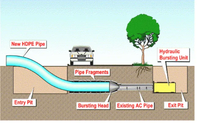
Figure 2.24. Pipe bursting (Dayton & Knight, Ltd.) ...30
Figure 2.25. Pipe splitting (RJM Company) ...30
Figure 2.26. Close-fit pipe (Insituform Technologies Inc.) ...31
Figure 2.27. Suggested iterative approach for trenchless projects (from Richardson et al. 2003) ...34
Figure 3.1. Trenchless-related backgrounds of respondents to Iowa survey ...44
Figure 3.2. Trenchless-related backgrounds of respondents to the Midwest survey ...45
Figure 3.3. Trenchless-related backgrounds of respondents to the national survey ...46
Figure 3.4. Geographical distribution of respondents to national survey ...46
Figure 3.5. Trenchless technologies experienced in practice by Iowa survey respondents ...47
Figure 3.6. Trenchless technologies experienced in practice by Midwest survey respondents ...47
Figure 3.7. Trenchless technologies experienced in practice by national survey respondents ...48
Figure 3.8. Iowa survey respondents seeing pavement distress or other problems as a result of using trenchless methods ...49
Figure 3.9. Midwest survey respondents encountering pavement deformations caused by trenchless methods ...49
Figure 3.10. Midwest survey responses for appropriateness of current QC/QA for trenchless projects ...51
Figure 3.11. National survey responses for appropriateness of current QC/QA for trenchless
projects ...51
Figure 3.12. Iowa survey responses regarding which trenchless method was considered least favorable ...52
Figure 3.13. Midwest survey ratings of reliability of trenchless technologies ...53
Figure 3.14. National survey ratings of reliability of trenchless technologies ...53
Figure 3.15. Pavement cracking caused by HDD installation ...56
Figure 3.16. Surface heave on HDD project ...57
Figure 4.1. Locations of trenchless construction projects visited ...58
Figure 4.2. Location of auger boring project (bore path in red) on State Street in Ankeny, IA ....61
Figure 4.3. North section of State Street above boring; insertion pit visible at right ...62
Figure 4.4. Launching pit ...62
Figure 4.5. Pipe and auger boring machine operation, with fluid supply line, water line, and steering rod running along top of pipe ...63
Figure 4.6. Sandy soil deposited out of auger boring machine ...64
Figure 4.7. Clayey weathered shale deposited out of auger boring machine ...64
Figure 4.8. Weathered shale deposited out of auger boring machine ...64
Figure 4.9. Spacers on 18-inch PVC carrier pipe to allow pipe to “float” in casing ...65
Figure 4.10. Location of pipe jacking project (bore path in red) on Keo Way in Des Moines, IA ...66
Figure 4.11. Plan view of project site; bore path in yellow ...67
Figure 4.12. Launching pit with trench box and steel plates ...68
Figure 4.13. Trench box before installation began ...68
Figure 4.14. Segments of 10-foot by 5-foot RCBCs ...69
Figure 4.15. Jacking begins on the first box pipe section ...69
Figure 4.16. Mini road header used to excavate soil as pipe was jacked in ...70
Figure 4.17. Skid loader used to move spoil from pipe to trench box to be removed by backhoe 70 Figure 4.18. Location of the project site (bore path in red) on Highway 63 (McCloud Avenue) near New Hampton, IA ...72
Figure 4.19. View from point A looking west across Highway 63 toward point B ...73
Figure 4.20. Partially flooded launching pit at point A, with track installed prior to tunneling ....73
Figure 4.21. TBM before starting the bore ...74
Figure 4.22. Existing granular backfill over a drainage pipe begins to slough away ...74
Figure 4.23. Boulders removed from the borehole (12 to 18 inches in diameter) ...75
Figure 4.24. Pipe being jacked into the soil behind the TBM ...76
Figure 4.25. Soil gradation curves for depths of 3 to 5 feet at Highway 63 site ...77
Figure 4.26. Location of auger boring project (bore path in red) at Delaware Avenue in Ankeny, IA ...79
Figure 4.27. Profile view of the project; bore path in yellow ...79
Figure 4.28. Launching pit with Delaware Avenue in background ...80
Figure 4.29. Launching pit with shoring and gravel base ...80
Figure 4.30. Launching pit before a new 20-foot pipe section is lowered into place ...81
Figure 4.31. Protruding casing after boring is finished ...81
Figure 4.32. PVC carrier pipe with visible spacers ...82
Figure 4.34. Location of HDD (bore path in red) at Johnny Majors Practice Field in Ames, IA .84
Figure 4.35. Plan view of the project site (bore path in yellow) taken from the plan set ...85
Figure 4.36. Directional drilling machine pushing pilot bore from point A to point D...87
Figure 4.37. Twelve-inch-diameter reamer ...87
Figure 4.38. Surface heave in background and frac-out in foreground ...88
Figure 4.39. Edge of frac-out region with drilling fluid at the ground surface ...89
Figure 4.40. Second frac-out near location of earlier surface heave ...89
Figure 4.41. Reamer shown jetting drilling fluid in point D exit pit just before pullback ...90
Figure 4.42. Installation of two conduits connected behind 18-inch reamer at point D ...91
Figure 4.43. Capped 4-inch HDPE pipes after installation at point E next to Beach Avenue ...92
Figure 4.44. Drill rig used by research team to recover soil samples ...93
Figure 4.45. Soil gradation curves for point B...94
Figure 4.46. Soil gradation curves for point C...95
Figure 4.47. Vertical effective stress vs. void ratio for soil from depths of 11.5 to 12.1 feet at point B ...96
Figure 4.48. Vertical effective stress vs. void ratio for soil from depths of 6.1 to 6.7 feet at point C ...96
Figure 4.49. Multistage consolidated undrained test stress vs. strain for soil at point B ...97
Figure 4.50. Multistage consolidated undrained test q′ vs. p′ for soil at point B ...97
Figure 4.51. Multistage consolidated undrained test stress vs. strain for soil at point C ...98
Figure 4.52. Multistage consolidated undrained test q′ vs. p′ for soil at point C ...99
Figure 4.53. Clay-caked drill bit shown after emerging into the exit pit at point D ...100
Figure 4.54. Geokon model 4830 push-in pressure cell (from Geokon) ...101
Figure 4.55. Location of pressure cell testing at Spangler Geotechnical Laboratory in Ames, IA ...102
Figure 4.56. Total lateral earth pressure, pore water pressure, and temperature measured at depth of 6.5 feet ...103
Figure 4.57. Location of HDD project (bore path in red) at Osborn Drive in Ames, IA ...105
Figure 4.58. Plan view of the project site; bore path in yellow ...105
Figure 4.59. Potholing to verify position of nearby utilities ...106
Figure 4.60. Directional drilling machine ...107
Figure 4.61. Fourteen-inch reamer ...107
Figure 4.62. Heat-welded HDPE pipe joint ...108
Figure 4.63. HDPE pipe being pulled from exit pit at point C to launching pit at point A ...108
Figure 4.64. Drilling fluid at ground surface resulting from frac-out ...109
Figure 4.65. Push-in pressure cell before installation ...110
Figure 4.66. Push-in pressure cell after installation ...110
Figure 4.67. Profile of pressure cell and borehole (looking east) ...111
Figure 4.68. Total lateral earth pressure, pore water pressure, and temperature measured 1.3 feet from bore centerline ...112
Figure 4.69. Soil gradation curves for depths of 1.5 to 3 feet and 3 to 5 feet ...114
Figure 4.70. Consolidation test graph showing vertical effective stress vs. void ratio ...114
Figure 4.71. Stress vs. strain curves from multistage consolidated undrained test ...115
Figure 4.72. q’ vs. p’ curves from multistage consolidated undrained test ...116
Figure 4.73. Location of HDD project (bore path in red) across Wallace Road in Ames, IA ...117
Figure 4.75. Looking east across Wallace Road toward exit pit at point C ...119
Figure 4.76. Pilot bore drill bit attached to drill rig ...120
Figure 4.77. Directional drilling machine ...120
Figure 4.78. Ten-inch reamer ...121
Figure 4.79. Second pipe emerges at point A and reamer is visible in front of the pipe ...121
Figure 4.80. Drilling a borehole through asphalt ...122
Figure 4.81. Cross-section showing pressure cells and borehole (looking west) ...123
Figure 4.82. Push-in pressure cells in place at point B (looking south) ...124
Figure 4.83. Total lateral earth pressure, pore water pressure, and temperature measured 3.8, 5.4, 9.5, and 11.5 feet from centerlines of bores ...125
Figure 4.84. Soil gradation curves for depths of 4 to 6 feet ...127
Figure 4.85. Location of HDD project (bore path in red) at the Hub in Ames, IA ...128
Figure 4.86. Plan view of project site; bore paths in yellow ...129
Figure 4.87. Directional drilling machine ...130
Figure 4.88. Push-in pressure cell after installation ...132
Figure 4.89. Push-in pressure cells in place ...132
Figure 4.90. Profile showing pressure cells and borehole (looking southwest) ...133
Figure 4.91. Push-in pressure cells being removed ...133
Figure 4.92. Total lateral earth pressure, pore water pressure, and temperature measured 3.5, 4.5, 7, and 8 feet from centerlines of bores ...135
Figure 4.93. Soil gradation curves for the Hub ...137
Figure 4.94. Location of HDD project (bore path in red) on Pammel Drive in Ames, IA ...138
Figure 4.95. Plan view of project site taken from plan set; bore path in yellow ...139
Figure 4.96. Directional drilling machine drilling from point C to D ...140
Figure 4.97. View north from point D to C of pilot bore advancing under Pammel Drive ...140
Figure 4.98. HDPE pipe (8-inch diameter) capped at point C after installation from points C to D; locate wire visible ...141
Figure 4.99. HDD rigs set up for 80-foot bore from points C to D (left machine) and 400- foot-bore from points C to A (right machine) ...141
Figure 4.100. Drill bit (5-inch diameter) emerging at point A ...142
Figure 4.101. Reamer (14-inch diameter) pulled into borehole at point A (clockwise from upper left) ...143
Figure 4.102. HDPE pipe (8-inch diameter) pulled into borehole at point A ...143
Figure 4.103. Installing push-in pressure cell ...144
Figure 4.104. Bore seen approaching the two pressure cells (left) ...145
Figure 4.105. Profile showing pressure cells and borehole (looking west) ...145
Figure 4.106. Total lateral earth pressure, pore water pressure, and temperature measured 2.1 and 3.4 feet from centerline of bore from points C to A ...147
Figure 4.107. Location of IAMU’s Safety and Training Field on NE 70th Avenue in Ankeny, IA; bore path shown in red ...149
Figure 4.108. Contractor equipment including air compressor and vacuum tank used for dewatering ...150
Figure 4.109. Grundomat reciprocating stepped-cone chisel head ...151
Figure 4.110. Launching the mole and adjusting line and grade using telescopic aiming frame 151 Figure 4.111. Locating mole after it emerged at point C into exit pit, which was flooded ...152
Figure 4.113. Entry pit at point A as 0.75-inch copper pipe was pulled into 2.5-inch-diameter
hole ...153
Figure 4.114. Exit pit at point C (foreground), entry pit at point A (background), and pressure cells at point B (middle) ...154
Figure 4.115. Profile showing pressure cells and borehole (looking north) ...154
Figure 4.116. Total lateral earth pressure, pore water pressure, and temperature measured 1.7 and 3.1 feet from centerline of bore ...155
Figure 4.117. HDD project location (bore path in red) along State Avenue in Ames, IA ...157
Figure 4.118. Plan view of project site taken from the plan set; bore path in yellow ...157
Figure 4.119. Pit at point B ...158
Figure 4.120. Directional drilling machine ...159
Figure 4.121. Truck with drilling fluid mixing tank (top right) worker with handheld locator (center) monitors advancing pilot bore depth and position ...159
Figure 4.122. Pilot bore emerging from exit pit at point D ...160
Figure 4.123. Reamer (16-inch diameter) attached to drill string ...160
Figure 4.124. Certa-Lok® bell (16-inch diameter) connecting pipe sections (12-inch diameter) 161 Figure 4.125. PVC pipe (12-inch diameter) being pulled into borehole from point D with a 16-inch diameter reamer leading ...161
Figure 4.126. Push-in pressure cells being installed ...162
Figure 4.127. Profile showing pressure cells and borehole (looking south) ...162
Figure 4.128. Bore approaching two pressure cells ...163
Figure 4.129. Total lateral earth pressure, pore water pressure, and temperature measured 2.1 and 3.4 feet from centerline of bore ...164
Figure 4.130. Total pressures measured during pilot bore for Ames Hub HDD project installing two 6-inch pipes in well-graded sand with silt and gravel ...169
Figure 4.131. Total pressures measured during pre-reaming stage for Ames Hub HDD project ...169
Figure 4.132. Total pressures induced by reamer and pipe pullback stage for Ames Hub project ...170
Figure 4.133. Comparison of stress calculations and actual measurements during 4-inch pilot bores...171
Figure 4.134. Comparison of stress calculations and actual measurements during 5.5-inch pilot bores...171
Figure 4.135. Calculation of radial pressure for a given change in area over area and external pressure ...172
Figure D.1. Location of auger boring project on SE 6th Avenue and SE 64th Street in Des
Moines, IA; bore path in red ... D-1
Figure D.2. Potholing by edge of pavement ... D-2
Figure D.3. Launching pit with terraced sides and a gravel base ... D-3
Figure D.4. Twenty four inch concrete pipe ... D-3
Figure D.5. Launching pit at point A being filled in as the installation is completed ... D-3
Figure D.6. Soil gradation curves for depths of 8 to 10 feet ... D-5
Figure D.7. The location of the auger boring project at Grand Avenue in Des Moines, IA;
bore path in red ... D-6
Figure D.8. View of the project looking from the launching pit at point A across Grand
Figure D.9. A potholing pit covered and marked ... D-8
Figure D.10. A backhoe lowers a new 20 foot section of steel pipe into the launching pit ... D-8
Figure D.11. Pipe and auger boring machine as a new pipe segment is being fitted to the
machine and welded to the pipeline ... D-8
Figure D.12. The location of the auger boring project at Osborn Drive in Ames, IA; bore
path in red ... D-10
Figure D.13. Launching pit with shoring and a gravel base ... D-12
Figure D.14. First pilot bore emerging in the receiving pit ... D-12
Figure D.15. First casing being bored from the launching pit ... D-12
Figure D.16. The first ductile iron water pipe with casing spacers attached is placed by
backhoe into the steel casing ... D-13
Figure D.17. Both casing pipes after boring are seen from the launching pit, and the carrier pipe can be seen in the casing pipe on the left ... D-13
Figure D.18. The final connection of pipe sections in the launching pit ... D-13
Figure D.19. Soil gradation curve for depths of 6 to 8 feet ... D-14
Figure D.20. The location of the HDD along Osborn Drive in Ames, IA; bore path in red .... D-16
Figure D.21. Plan view of the project site; bore path in yellow ... D-16
Figure D.22. Directional drilling machine ... D-18
Figure D.23. Fourteen inch diameter reamer ... D-18
Figure D.24. Eight inch HDPE pipe ... D-18
Figure D.25. Soil gradation curve for depths of 3 to 5 feet ... D-19
Figure D.26. The location of the auger boring project in Tama, IA; bore path in red ... D-21
Figure D.27. Auger boring machine on its track against the sheet pile thrust block ... D-22
Figure D.28. A new 20 foot long pipe section being welded to the pipeline... D-22
Figure D.29. The third pipe being installed ... D-23
Figure D.30. The location of the HDD along Beach Road in Ames, IA; bore path in red ... D-24
Figure D.31. Plan view of the project site; bore path in yellow ... D-24
Figure D.32. Directional drilling machine ... D-26
Figure D.33. The 4 inch diameter HDPE pipes connected to the building near point B ... D-26
Figure D.34. Soil gradation curves for depths of 5 to 7 feet ... D-27
Figure D.35. The location of the HDD project across 210th Street in Boone, IA; bore path in red ... D-28
Figure D.36. Plan view of the project site; bore path in yellow ... D-29
Figure D.37. The directional drilling machine ... D-30
Figure D.38. Drilling fluid being vacuumed from the bottom of the exit pit at B ... D-31
Figure D.39. Five inch diameter pilot bore drill bit ... D-31
Figure D.40. Soil gradation curves for depths of 5 to 7 feet ... D-32
Figure D.41. The location of the HDD installation along Marion Street in Boone, IA; bore path in red ... D-33
Figure D.42. Plan view of the project site; bore path in yellow ... D-34
Figure D.43. The directional drilling machine ... D-35
Figure D.44. Drilling fluid at the bottom of the exit pit at B ... D-36
Figure D.45. Drilling fluid close-up showing texture ... D-36
Figure D.46. Twenty-four inch wagon wheel reamer ... D-36
LIST OF TABLES
Table 2.1. Trenchless construction methods (after Najafi 2005) ...6
Table 2.2. Ground conditions and suitability of trenchless road crossing methods (after Iseley et al. 1999) ...7
Table 2.3. Relative comparison of TBM and MTBM (from Mathy and Kahl 2003) ...14
Table 2.4. Trenchless rehabilitation methods (Najafi 2005) ...25
Table 2.5. State-of-the-art horizontal sampling equipment (from Allouche et al. 2001) ...37
Table 2.6. Operational risks in HDD installations (Baumert and Allouche 2003) ...41
Table 4.1. Summary of projects ...60
Table 4.2. Chickasaw County project soil parameters ...77
Table 4.3. Delaware Avenue and 47th Street auger bore project soil parameters ...83
Table 4.4. Johnny Majors Practice Field project soil parameters at point B ...93
Table 4.5. Johnny Majors Practice Field project soil parameters at point C ...94
Table 4.6. Spangler Geotechnical Laboratory testing soil parameters ...102
Table 4.7. Osborn Drive second HDD project soil parameters ...113
Table 4.8. Ames Wallace Road project soil parameters ...126
Table 4.9. Soil parameters for the Hub project in Ames, IA ...136
Table 4.10. Soil parameters for Pammel Drive project ...148
Table 4.11. Field monitoring results ...168
Table D.1. SE 6th Avenue and SE 64th Street project soil parameters ... D-4
Table D.2. Ames, West Osborn Drive auger boring project soil parameters ... D-14
Table D.3. Ames, West Osborn Drive first HDD project soil parameters... D-19
Table D.4. Ames, Beach Road project soil parameters ... D-27
ACKNOWLEDGMENTS
The authors would like to thank the Iowa Highway Research Board for funding this research. The authors would also like to thank all of the contractors and design professionals who shared their valuable time and expertise during this project. They contributed immensely to this research.
The technical advisory committee for this project included the following people:
• Dick Burhan
• Mark Dunn, Iowa Department of Transportation, Research and Technology Bureau
• Carl Elshire, City of Des Moines
• Jeff Hansen, City of Des Moines
• Dean Herbst, Iowa Department of Transportation
• John Joiner, City of Ames
• Marv Klein, Vermeer Manufacturing
• Jeff Krist, City of Council Bluffs
• Dave Miller, City of Des Moines
• Greg Mulder, Iowa Department of Transportation
• Al Munsterman, Snyder and Associates
• Tony Rose, Envirotraxx
• Roger Schletzbaum, Marion County
• Lee Tippe, City of Cedar Rapids
• Dave Wallace, City of Cedar Rapids
• Paul Wiegand, Institute for Transportation
EXECUTIVE SUMMARY
Trenchless technologies are methods used for the construction and rehabilitation of underground utility pipes. These methods are growing increasingly popular due to their versatility and their potential to lower project costs. However, the use of trenchless technologies in Iowa and their effects on surrounding soil and nearby structures has not been adequately documented.
Surveys of and interviews with professionals working in trenchless-related industries in Iowa were conducted, and the results were analyzed and compared to survey results from the United States as a whole. The surveys focused on method familiarity, pavement distress observed, reliability of trenchless methods, and future improvements. Results indicate that the frequency of pavement distress or other trenchless-related issues are an ongoing problem in the industry. Inadequate soil information and quality control/quality assurance (QC/QA) are partially to blame.
Fieldwork involving the observation of trenchless construction projects was undertaken with the purpose of documenting current practices and applications of trenchless technology in the United States and Iowa. Field tests were performed in which push-in pressure cells were used to
measure the soil stresses induced by trenchless construction methods. A program of laboratory soil testing was carried out in conjunction with the field testing.
Soil testing showed that the installations were made in sandy clay or well-graded sand with silt and gravel. Pipes were installed primarily using horizontal directional drilling with pipe
diameters from 3 to 12 inches. Pressure cell monitoring was conducted during the following construction phases: pilot bore, pre-reaming, and combined pipe pulling and reaming. The greatest increase in lateral earth pressure was 5.6 psi and was detected 2.1 feet from the
centerline of the bore during a pilot hole operation in sandy lean clay. Measurements from 1.0 to 2.5 psi were common.
CHAPTER 1. INTRODUCTION
1.1 Problem Statement
Trenchless technologies are a group of methods for constructing and rehabilitating underground utilities without using open-cut excavations. The use of trenchless technologies is increasing due to the growing need to replace aging utility infrastructure and the need for more flexible
solutions for installing new pipes. Many applications exist for trenchless construction methods (TCMs), which take advantage of the ability to install utility lines with minimal disruption of facilities above and next to the alignment of the new utility line. An example is the ability to install utility pipes across busy streets without disrupting traffic.
Limited technical data currently exists on the relationship between the cutting mechanism, conduit materials and dimensions, and their effects on soil properties and performance of subgrade soil and pavement systems. A better understanding of these relationships would allow improvements to be made to the design and practice of these construction methods, which could result in the improved performance of overlying pavement and nearby underground structures.
1.2 Objectives
This research was undertaken with two primary aims:
• To document the current practices and applications of trenchless technology in the United States and, particularly, in Iowa.
• To evaluate the effects of trenchless construction on surrounding soil and adjacent structures.
The project was intended to provide information on different trenchless methods and to document current construction and quality control/quality assurance (QC/QA) practices used across Iowa and the United States. A testing program was implemented to address these objectives.
1.3 Methodology
This report is divided according to the research tasks that were conducted. A literature review was first performed to assemble information on the current practice of trenchless technologies. The literature review examines the rationale for trenchless technology and introduces the major trenchless construction and rehabilitation methods. Soil investigation methods for trenchless projects, QC/QA, the effects of trenchless technologies on surrounding soil, and design processes are all discussed. A program of surveying and interviewing trenchless practitioners was
CHAPTER 2. LITERATURE REVIEW
2.1 Introduction
Trenchless technologies can be defined as a group of methods for constructing and rehabilitating underground utilities that require minimal surface excavation and provide important new
alternatives to traditional open-cut methods of utility pipe installation. These techniques offer many unique advantages. Trenchless methods are becoming increasingly important as the number of utility pipes for water, gas, and telecommunications and storm and sanitary sewers multiply beneath roads.
Open-cut methods of utility pipe installation involve excavating a trench along the proposed pipeline path and placing the pipe in the trench. Other names for this method are open-cut, open trench, utility cut, dig-and-install, dig-and-repair, or dig-and-replace. These methods can involve additional construction complications, such as road detours, traffic control, trench excavation and shoring, dewatering, backfilling and compaction operations, bypass pumping systems, and reinstatement of the surface, which can cause construction efforts to be focused on peripheral tasks rather than the pipe installation itself.
Open-cut methods can have negative effects that may sometimes be avoided by using trenchless technology. Frequently, utility pipe projects are located beneath pavement that must be removed to perform open-cut work. The natural gas industry estimates that almost 60% of their pipes run below pavement (Najafi 2005). Peters (2002) observes that premature distress often seen in newly paved utility cuts may include cracks that allow water to enter and soften the base course and cause loss of pavement support, which can result in further pavement deterioration. Arudi et al. (2000) add that such problems directly influence the pavement integrity, life, aesthetic value, and drivers’ safety. Bodocsi et al. (1995) quantify this observation by noting that new pavement should last between 15 and 20 years, but pavement over utility cuts exhibits a shortened life span of about 8 years.
Open-cut installations can also carry significant economic disadvantages. The American Public Works Association (APWA 1997) reported that a study conducted in Burlington, Vermont, found that the weakening of pavement caused by utility cuts required an additional asphalt overlay that was 0.75 to 1.5 inches thick to compensate. The additional cost was $522,000 per year. Additionally, Los Angeles, California, reported spending $16.4 million per year on pavement overlays to strengthen pavements damaged by utility cuts (APWA 1997). In addition to pavement overlays, a report by Najafi (2005) states that up to 70% of the total cost of
underground utility projects can be attributed to backfilling, compaction, and replacing landscaping and pavement.
methods (Gangavarapu et al. 2003). As technology and expertise continue to improve for this still-maturing industry, it is expected that trenchless technologies will be utilized for increasing numbers of underground utility projects (Najafi 2005).
Additional advantages of trenchless methods in comparison to open-cut methods are listed by several researchers (Stidger 2002; Barsoom 1995; Khogali and Mohamed 1999; and Yung and Sinha 2007), as summarized below:
• Reduction in required surface restoration
• Reduction of damage to adjoining utilities
• Decreased disturbance to local residents and businesses
• Increased flexibility in alignment selection
• Increased flexibility in choosing depth of new installation, which may allow more favorable soil conditions to be used
• Less relationship between cost and depth of installation
• Reduced number of utility relocations
• Reduction in the amount of spoil that requires disposal
• Reduced need for dewatering
• Reduction in access requirements, which is advantageous in urban settings and under rivers, etc.
• Improvement in safety for the public and for jobsite workers
• Ease of renewal of existing pipelines
• Mitigation of air, water, and noise pollution
• Reduced disturbance to traffic flow
• Ability to install pipe in frozen ground during cold weather
• Possibility of increased speed of work
The designation “trenchless technologies” can be somewhat misleading. Many “trenchless” methods exist, and all share the common characteristic of minimal, but often some, surface disruption. Trenchless technologies are commonly divided into two categories: TCMs and trenchless rehabilitation methods (TRMs).
Although trenchless methods have many advantages over open-cut methods, uncertainties about some trenchless methods can cause concern. Iseley and Gokhale (1997) observed that some trenchless methods carry the risk of subsidence, surface heave, and leaking drilling fluid. Additionally, compared to an open-cut project, the often higher risk inherent in a trenchless project can make a failure considerably more expensive (O’Reilly and Stovin 1996).
This literature review intends to document the current TCMs and TRMs, with an additional focus on the effects of trenchless construction on adjacent structures, including buried pipes and
pavements. Additionally, the literature review will summarize existing soil investigation and QC/QA methods.
2.2 Trenchless Construction Methods (TCMs)
TCMs encompass a family of methods that are used to install new underground utility pipe without requiring an open-cut. While most of these methods do involve a limited amount of surface disruption, they require much less compared to open-cut methods.
Myers et al. (1999) estimated that 150,000 miles of new conduit is installed each year in North America. The distribution of new conduit construction by end use (see Figure 2.1) shows that the gas and telecommunication industries require the most.
Figure 2.1. New conduit type breakdown (after Stein et al. 1999)
Numerous trenchless construction methods exist, and they are still evolving as experience and technology improve. Jung and Sinha (2007) reported that the following methods are most commonly used:
17%
19%
16% 14%
24%
10%
Electric Cables Gas
Water Sewage
• Microtunneling
• Conventional tunneling
• Compaction methods (impact moling)
• Horizontal directional drilling (HDD)
• Pipe jacking
• Pipe ramming
• Auger boring
• Water jetting
• Pilot tube microtunneling (PTMT)
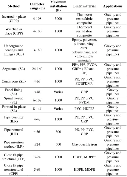
[image:28.612.67.515.265.641.2]Table 2.1 shows important characteristics of the most common TCMs.
Table 2.1. Trenchless construction methods (after Najafi 2005)
Method Diameter range (in) Maximum installation (ft)
Pipe material Applications
Accuracy of Installation Pipe jacking and conventional tunneling
≥42 1,500 RCP*, GRP*, steel
Pressure and
gravity pipe ± 1 in
Auger boring 4–60 600 Steel Road and rail crossing
±1% of the bore length
Microtunneling 10–136 500–1,500
RCP, GRP, VCP*, DIP*,
Steel, PCP*
Gravity pipe ± 1 in
Mini-HDD 2–12 600
PE, steel, PVC*, clay,
FRP*
Pressure
pipe/cable Varies
Midi-HDD 12–24 1,000 PE, steel,
ductile iron Pressure pipe Varies Maxi-HDD 24–48 6,000 PE, steel Pressure pipe Varies
Pipe ramming <120 400 Steel Road and rail crossing
Dependent on setup Compaction
methods <8 250 Any Pipe or cable
±1% of the bore length
PTMT 6–10 300
RCP, GRP, VCP, DIP, Steel, PCP Small diameter gravity pipes
± 1 in
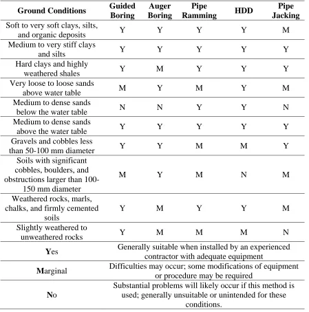
Pipe diameter, length of bore, pipe material, type of utility, and ground conditions affect the construction method chosen. The location of the bore relative to the water table and the type of soil have significant impacts on the effectiveness of the various methods (Kenny et al. 2003). Table 2.2 summarizes how ground conditions influence the suitability of various TCMs and provides general guidelines for the suitability of common trenchless techniques in different soil types. Table 2.2 indicates that loose sand, dense sand below the water table, soil with cobbles, and significantly weathered rocks provide the most significant challenges for most trenchless construction techniques. Medium to very stiff clays and silts and medium to dense sands above the water table are the only soils that are suitable for all TCMs.
Table 2.2. Ground conditions and suitability of trenchless road crossing methods (after Iseley et al. 1999)
Ground Conditions Guided
Boring Auger Boring Pipe Ramming HDD Pipe Jacking
Soft to very soft clays, silts,
and organic deposits Y Y Y Y M
Medium to very stiff clays
and silts Y Y Y Y Y
Hard clays and highly
weathered shales Y M Y Y Y
Very loose to loose sands
above water table M Y M Y M
Medium to dense sands
below the water table N N Y Y N
Medium to dense sands
above the water table Y Y Y Y Y
Gravels and cobbles less
than 50-100 mm diameter Y Y M M Y
Soils with significant cobbles, boulders, and obstructions larger than
100-150 mm diameter
M Y M N M
Weathered rocks, marls, chalks, and firmly cemented
soils
Y M Y Y M
Slightly weathered to
unweathered rocks Y M M M N
Yes Generally suitable when installed by an experienced contractor with adequate equipment
Marginal Difficulties may occur; some modifications of equipment or procedure may be required
No
Substantial problems will likely occur if this method is used; generally unsuitable or unintended for these
conditions.
2.2.1 Horizontal Auger Boring and Guided Auger Boring
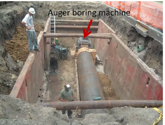
The American Society of Civil Engineers (ASCE) (2004) defines horizontal auger boring as “a technique for forming a bore from a drive pit to a reception pit by a rotating cutting head. Spoil is removed back to the driveshaft by helically wound auger flights rotating in a steel casing.” Horizontal auger boring, also known as “jacking and boring,” is one of the oldest trenchless methods and, according to the North American Society for Trenchless Technology (NASTT), is also one of the most cost-effective (NASTT 2006). Auger boring is known to be the most widely used trenchless method for installing steel pipes and casings (ASCE 2004).
Horizontal auger boring can be used to install pipes ranging from 4 to 72 inches in diameter for a length averaging between 175 and 225 feet with a maximum distance of 600 feet (ASCE 2004). There is no limit for the potential installation depth. Horizontal auger boring is suitable for a variety of soil conditions but experiences the most difficulty in sands below the water table (Munro and McMurdie 1985).
For highway and railroad crossings, casing will often be installed using trenchless methods, and then the product pipe (the actual utility pipe) will be installed in the casing. This technique prevents leaks in the product pipe from causing damage to the roadbed.
Figure 2.2. Launching pit with auger boring machine installing pipe
Figure 2.3. Typical auger boring system (Iseley and Gokhale 1997)
called a “wing” to the side of the casing to induce the pipe to veer in the desired direction as it is jacked.
Figure 2.4. Waterline grade measurement pipe, steering rod, and fluid supply pipe attached to top of casing
The guided auger boring method, also known as the “pilot tube method” and “guided thrust boring,” is defined by ASCE (2004) as, “the term applied to auger boring systems that are similar to microtunneling, but have the guidance mechanism actuator sited in the driveshaft. This pipe installation method uses pilot tubes and a theodolite to install small-diameter pipes with high accuracy.”
A launching pit as small as 8 feet in width is first constructed, and the hydraulic pipe jacking machine is installed at the appropriate depth. A pilot bore is then drilled, which is done by jacking a 1- to 4-inch thick cutting head into the soil along the centerline of the bore. The asymmetric cutting head is spun while jacking to bore a straight line and displace and compact the soil laterally into the borehole walls (Boschert 2007). Additional sections of drill rod are added in the launching pit as the bore progresses. When the theodolite position monitoring system detects that the pilot bore has shifted off course, steering corrections are made by jacking the asymmetric cutting head at a stationary and specific angle, inducing the bore to veer in the desired direction. This pilot boring process closely resembles that used during HDD.
Figure 2.5. Vitrified clay pipe being installed using guided auger boring (from Allen Watson, Ltd.)
Guided auger boring is not recommended for use in soils with boulders because the pilot tubes may be deflected, and guided boring is not recommended for sands below the water table because of the possibility of settlement due to water flowing out of the soil through the pipe (Fisher 2003).
More information on horizontal and guided auger boring is available in ASCE’s Horizontal Auger Boring Projects manual of practice (ASCE 2004).
2.2.2 Tunneling and Microtunneling
Man-entry tunnel boring machines (TBMs) and remotely operated microtunnel boring machines (MTBMs) are two methods that may be used for line- and grade-critical pipelines greater than 42 inches in diameter. These two methods share many common features and equipment but differ in that MTBMs tend to deliver better accuracy and performance than TBMs, though with an
increased cost. Both methods have relative strengths and weaknesses, and it is generally thought that the choice between MTBMs and TBMs should be made based on site-specific subsoil conditions, as will be discussed.
either a conveyor or a cart on which the cuttings are deposited at the cutting face before they are transported out of the machine for disposal (Mathy and Kahl 2003). The most common diameters for TBMs are 48 to 72 inches, although TBMs can be as large as 12 feet in diameter. A cross-section of a TBM is shown in Figure 2.7.
[image:34.612.222.392.145.350.2]Figure 2.6. Rotating cutter head TBM
Figure 2.7. Utility tunneling machine diagram (Miller the Driller)
10 to 136 inches or more and have virtually no depth limitation. A cross-section of a microtunneling procedure is shown in Figure 2.9.
[image:35.612.169.445.116.324.2]Figure 2.8. MTMB with disc cutter head on display (photo by Charles T. Jahren)
Figure 2.9. Microtunneling in urban setting (Irish Tunneling, Ltd.)
When using either type of tunneling method, the most critical risk is surface settlement. The two main ways to prevent settlement from occurring are maintaining the stability of the excavation face and avoiding inadvertent loss of soil into the tunnel. To attain these goals, the primary geotechnical concern when performing utility tunneling is accurately describing and predicting soil behavior at the face of the tunnel (Mathy and Kahl 2003). For example, the presence of boulders and saturated sandy soils can be particularly problematic.
surface settlement. The prevention of inflow by dewatering along the tunnel alignment is not always possible in urban environments; however, microtunneling provides an effective solution when the MTBM is equipped with a slurry spoil removal system. The computer of the MTBM continuously monitors slurry pressures in the borehole to offset the external hydrostatic groundwater pressure, making microtunneling very effective in areas with groundwater and flowing, highly permeable soils. Conversely, the open face of TBMs can make these machines unsuitable for flowing soil and water conditions. TBMs can be fitted with a closed-face shield that allows groundwater inflow to be controlled in certain soils, such as low-permeability clays. Even in these favorable conditions, TBMs are restricted to working in less than 10 feet of unbalanced groundwater head. In highly permeable granular soils, TBMs may be unable to control any groundwater inflows and would require dewatering or ground treatment for the bore to proceed (Mathy and Kahl 2003).
When tunneling with a shallow depth of soil cover, TBMs have the advantage of not using pressurized slurry at the boring face, thereby avoiding the risk of soil hydrofracture. TBMs also possess an advantage over MTBMs in certain soil conditions because of the operator’s ability to access the face of the bore, which is not possible in microtunneling. This ability can be useful when encountering cobbles and boulders. Personnel can access the tunnel face where cobbles and boulders can be removed or broken down with hand tools and removed in pieces.
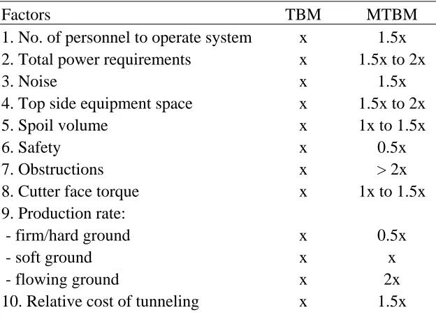
[image:36.612.71.383.490.722.2]Mathy and Kahl (2003) assert that MTBM pipe jacking is currently being specified for some projects for which conventional open- or closed-face TBMs may be a better option. This is because of a perception that microtunneling is a more effective method than conventional tunneling, regardless of the soil situation. In practice, the designer should consider the unique characteristics of a project and match them to the relative advantages of both methods before making a selection. Table 2.3 compares relative differences between TBM and MTBM technologies.
Table 2.3. Relative comparison of TBM and MTBM (from Mathy and Kahl 2003)
Factors TBM MTBM
1. No. of personnel to operate system x 1.5x 2. Total power requirements x 1.5x to 2x
3. Noise x 1.5x
4. Top side equipment space x 1.5x to 2x
5. Spoil volume x 1x to 1.5x
6. Safety x 0.5x
7. Obstructions x > 2x
8. Cutter face torque x 1x to 1.5x
9. Production rate:
- firm/hard ground x 0.5x
- soft ground x x
- flowing ground x 2x
2.2.3 Horizontal Directional Drilling (HDD)
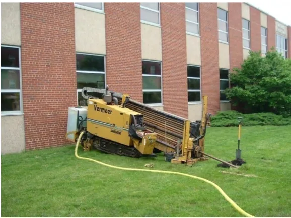
HDD is a TCM that utilizes a drilling rig to install pipelines beneath obstructions, such as roadways, driveways, historical areas, landscaped areas, rivers, and streams (Willoughby 2005). In the private sector, media and communication firms are using HDD to install telephone, fiber optic, and cable conduits and lines. The public sector utilizes HDD for repairing and replacing potable water mains, reclaimed water mains, storm water piping, sewage gravity piping, and force mains. Advantages of HDD include the ability to expedite projects and minimize impact on critical habitats while requiring smaller project footprints. HDD rigs can install pipes from 2 to 48 inches in diameter for distances up to 6,000 feet, depending on the size of the drill rig. HDD is effective in a variety of ground conditions, but installation is generally faster in clay soils than in sands. However, HDD is not effective for soils with a significant number of cobbles and boulders because they can deflect the bore and potentially damage the pipe as it is pulled into place. Nearly 4,000 HDD rigs operate daily across North America (Baumert and Allouche 2003).
The drill rig used for HDD can be described as essentially being a traditional drill rig for vertical drilling that is turned on its side (Neu 2004). Complete HDD systems usually include the drill rig, a trailer for transport, a power supply that is separate from the drill rig, a drilling fluid mixing and control system, water and drilling fluid tanks, a variety of drill bits, additional drill rods, and the necessary accessories, including the electronic sending and locating system (Treadway 1997).
[image:37.612.162.451.473.690.2]The presence of an existing underground pipe or wires presents a significant hazard to HDD operations. The drill machine operator may avoid these obstacles, however, if their exact location is known (Najafi 2005). The drill rig is then set up at one end of the planned bore (see Figure 2.10), while a receiving pit can be excavated at the other end to retrieve the equipment at the proper depth.
A small-diameter pilot bore, usually between 1 and 5 inches in diameter, is then drilled into the soil from the boring machine to the receiving pit (see Figure 2.11). The bore begins at the ground surface and proceeds downward at an angle of 8° to 15° until the target depth is reached
(Treadway 1997). The drill bit is advanced by pushing and spinning the drill rod using the hydraulic machinery of the drill rig. A sonde (transmitter) attached to the drill bit allows a
handheld locator at the surface to monitor the position of the drill bit in the ground. When course correction is not required, the drill rod is spun, which spins the attached bit and cuts the soil. The soil in the path of the drill hole is partially removed to the launching area and partially displaced and compacted into the sides of the borehole. Information was not available about the amount of soil displaced and the amount compacted into the sides of the borehole. When a course
correction is required, the bit is rotated to a specific angle measured by clock position. Then, the bit is pushed into the soil without rotation. The slant-head bit is shaped in such a way that it will deflect the drill rod in the desired direction (see Figure 2.12). Additional sections of drill rod are added as the bore progresses. These drill rods are made of a special alloy steel and are designed to handle the stresses caused by the sag bends and directional changes. The rods are hollow, permitting drilling fluid to be pumped through them to the bit (Woodroffe and Ariaratnam 2008).
Figure 2.11. Pilot bore being started by pushing drill bit into soil
The drilling fluid serves both to lubricate the borehole and drilling machinery and to stabilize the borehole walls. The fluid must also cool the sonde located behind the drill bit. Sometimes, plain water is used for bores of 50 feet or less and in certain geologic conditions (Najafi 2005). More often, clay polymers (bentonite with additives) or biodegradable chemical polymers that increase the fluid viscosity are added to the water to provide lubrication and improve the stability of the borehole walls. The appropriate drilling fluid mixture is determined by the properties of the soil at the site and the pH and calcium content of the local water.
Once the initial pilot hole has been completed and the drill bit has emerged into the exit pit, it will be replaced with a reamer (also called a “back reamer”) (see Figure 2.13) that will be rotated and pulled back toward the drilling machine. This process will both enlarge the hole and smooth any sharp bends that may have occurred while drilling the pilot hole. The back reaming may be completed in one pass or in several passes with reamers of progressively larger diameters. The product pipe will be attached to the reamer before the final pullback to complete the installation of the pipe (see Figure 2.14). Typically, product pipe pullback is the operation that causes the highest pullback stresses, due to the friction between the product pipe and the wall of the borehole. (Najafi, 2005)
Figure 2.14. Reaming and product line installation (from NASTT)
Project specifications require a weak-link device to be attached between the reamer and product pipe during installation. A weak-link protects the pipe from excessive tensile stresses. Newer equipment is also available, such as the “TensiTrak” device, that measures the pullback forces and reports the results to the operator (see Figure 2.15). American Society for Testing and Materials (ASTM) pipe standards are used to determine the allowable tensile load for setting weak-link devices.
Figure 2.15. Weak-link device (trade name “TensiTrak”) (NASTT 2005)
through which a continuous flow of drilling fluid washes unconsolidated material away, providing a pathway for the drill string.
Baumert et al. (2002) suggests that current design models fail to account for installations where a significant portion of the borehole is comprised of solid drill cuttings that are not entrained in the drilling mud. In this situation, annular mud flow is not maintained. Instead of considering this possibility, the design models currently used to predict pull loads for large, expensive
installations are based on assumptions of ideal borehole conditions. Specifically, these assumptions are a clean, stable borehole filled with low-viscosity drilling mud.
2.2.4 Pipe Jacking
The term “pipe jacking” may be used to describe either a specific TCM or a process that is used as part of other trenchless methods. When used to describe a specific trenchless method, pipe jacking refers to installation using hydraulic jacks located in the launching pit to push the pipe forward while workers inside the pipe perform the excavation and removal process using manual or mechanical means (see Figure 2.16). When the term is used to describe a process in a different trenchless method, pipe jacking describes an operation using a hydraulic jacking system to advance the pipe and cutting mechanism. Auger boring, tunneling, microtunneling, and pipe ramming are examples of different trenchless methods that use a jacking mechanism to advance the pipe and cutter head.
Figure 2.16. Pipe jacking with manual soil excavation (WK Construction)
Pipe jacking is used to install pipe that is greater than 42 inches in diameter and for lengths up to 1,500 feet. It is suitable for many clay and sandy soils; however, the open boring face makes the method inappropriate for installations beneath the water table, particularly in sandy soils.
2.2.5 Pipe Ramming
Pipe ramming is a trenchless construction procedure that involves pneumatically hammering a steel pipe into the soil formation (see Figure 2.17). The leading edge of the pipe can either be closed with a cone tip or be open. The cone-shaped end can be used for pipes up to 8 inches in diameter (Najafi et al. 2003). This limitation exists because the soil is entirely radially displaced during installation, resulting in significantly increased soil pressures on all sides of the pipe and increased risk of surface heave.
Figure 2.17. Pipe ramming diagram (Earth Tool Company, LLC)
Open-faced pipe ramming is usually used for pipes with diameters up to 55 inches and lengths up to 150 feet long. Pipes should be installation at a depth of at least 10 times the diameter of the product pipe. Pipe ramming is most commonly used for shallow installations under roads and railroads. For short bores of under 60 feet, the method can allow more cost savings than auger boring and HDD due to the faster set up times and faster installation times. Pipe ramming can be used in nearly all soil types except for solid rock. However, this method can be unsuitable at depths below the water table, especially in sands, because groundwater can flow through the pipe and enter the insertion pit. A drilling fluid similar to that used for HDD installations is used and is delivered to the cutting face through a small pipe located above the steel casing pipe.
Additional detail about pipe ramming is available in Simicevic and Sterling (2001).
2.2.6 Compaction Methods (Impact Moling)
Impact moling is a TCM that uses a pneumatic mole to bore a small diameter hole. Impact moling is used to install pipes with a diameter of up to 10 inches and a length of up to 200 feet. Pipes should be installed at a depth of at least 10 times the diameter of the product pipe or 3 to 4 feet, whichever is greater. This precaution is meant to prevent surface heave. The method is most frequently used to install small diameter pipes for gas, water, and cable lines (Simicevic and Sterling 2001).
potential for the borehole to collapse and because rocky soils can cause the mole to deflect from its course (Clarke 2004).
Figure 2.18. Impact mole
The procedure for impact moling starts by digging entry and exit pits for launching and retrieval. The next step is to position the mole in the bottom of the entry pit. The mole is laid in a starting cradle and an operator slowly eases it into the ground while a telescopic aiming frame is used to monitor line and grade (see Figure 2.19). Line and grade are continuously monitored and
adjusted until the mole has fully entered the soil. Steering is impossible, so the initial placement is critical. Drilling fluid is not used for impact moling. The mole hydraulically rams itself into the soil and proceeds through the soil to the exit pit without any possibility for further
Figure 2.19. Positioning mole before launching (Allen Watson, Ltd.)
Impact moling is the most widely used trenchless installation method. Recently, moles equipped with steering systems capable of curved trajectories and direction changes have become available but have not yet achieved widespread use (Peng et al. 2003). Detailed information on impact moling is available in Simicevic and Sterling (2001).
2.2.7 Pilot Tube Microtunneling (PTMT)
PTMT was first introduced in the United States in 1995 and has been becoming increasingly popular as an alternative to microtunneling. PTMT is used for installing small diameter pipes that require high accuracy. This method can be considered a hybrid of three existing trenchless boring methods. Similar to HDD, a pilot bore head with a slanted face is used (see Figure 2.20). The guidance system is identical to that used in conventional microtunneling, and the auger spoil removal system is similar to that used in auger boring (Boschert 2007).
PTMT has been growing in popularity due to low equipment costs, a small surface footprint, accuracy, and small launching pits. Pipe diameters of up to 32 inches can be accommodated, and maximum drive lengths are currently about 400 feet (Boschert 2007). The maximum lengths and diameters are increasing, however, as the guidance system is gradually improved with better optics and as additional thrust is available from more powerful hydraulic jacking systems. PTMT is most effective in soft soil conditions and is not considered suitable for soil with significant cobbles and boulders because these obstacles can impact steering. PTMT can be used above or below the water table (Najafi 2005).
A typical PTMT project begins with the excavation of circular jacking and receiving pits, which usually measure 6.5 to 8 feet in diameter. The jacking frame is then assembled in the launching pit. The PTMT machine is next set up at the correct line and grade using control points
established by a conventional surface survey. The boring begins by pushing the pilot tube into the soil at the correct line and grade. The slant-head drill bit (also called a steering head) is spun and pushed, and it displaces and compacts soil radially into the formation. The hollow stems of the drill rods provide a clear line of sight for a camera in the launching pit to view an LED target in the steering head and measure the line and grade. Once the steering head has reached the receiving pit on the correct line and grade, the camera guidance system can be removed because the pilot bore has established the centerline. The next step is to attach the reamer behind the final length of pilot tube in the launching pit (see Figure 2.21). The reamer is slightly larger in
diameter than the intended pipe. A casing of the same size as the reamer is connected behind the reamer, with an auger inside the casing to transport the cuttings back to the launching pit. The reamer is jacked into the soil, and the pilot tubing gradually emerges into the receiving pit. Finally, the auger finishes removing all of the spoil in the casing. The product pipe is then attached behind the auger casings in the launching pit, and the pipe is inserted in the borehole. As the pipe is jacked into place, lengths of the auger casing emerge in the receiving pit. Finally, the product pipe completely replaces the auger casing in the borehole and the installation is complete (Boschert 2007; Force et al. 2003).