Abstract
:
This study deals with the static analysis of the effect
of shape memory alloy using finite element analysis on
ansys software.In this paper, a simply supported carbon/epoxy
beam is considered.A point load of 10 KN is applied at the top
layer of the carbon/epoxy carbon/epoxy beam. The boundary
condition is same for with and without SMA wire. this research
work involves analysis of the 1000mm length carbon/epoxy
carbon/epoxy beam. the shape memory alloy wire is used at the
top surface above the neutral axis of the carbon/epoxy beam. The
shape memory alloy wire which is 10% by volume fraction of the
whole carbon/epoxy beam. After performing analysis we
compare both the result with SMA and without SMA wire. In this
analysis we compare the maximum deformation, Equivalent
(von-misses) stress and strain. From the above result, we have
seen the effect of shape memory alloy wire on the carbon/epoxy
beam. All the method which is used to analysis the carbon/epoxy
beam is controlled by ansys software.
Key Words: Carbon/Epoxy, Shape Memory Alloy, ANSYS
Workbench, Finite Element Analysis, Fiber Volume Fraction.
I.
INTRODUCTION
In the past few decades, we saw that shape memory
alloy(SMA) have the capability of supporting large inelastic
strain (H., 1987). The mathematical modeling of the
multi-dimensional and one-dimensional system made up of
shape memory alloy have received their attention in the
literature (Bernardini D, 2003). In this research paper, we
analyze the carbon/epoxy carbon/epoxy beam with and
without the use of shape memory alloy and compare the
result for stress, strain. And displacement. the shape memory
alloy wire is used is 10% by the volume fraction of the
carbon/epoxy beam. The material properties used to analysis
the composite beam is defined as the earlier researches to get
the efficient result (S.M.R. Khalili, 2013).The goal of the
study is to explore the effects for material shape memory
alloy wire when 10% of volume fraction is used in the
carbon/epoxy beam.
Revised Manuscript Received on May 06, 2019
Yatendra Saraswat, Department of civil engineering, GLA University, Mathura, India.
Sangam Yadav, Department of civil engineering, GLA University, Mathura, India.
Hemant Singh Parihar, Department of civil engineering, GLA University, Mathura, India.
Here in figure 1, we have the cross-section of the beam that is
designed in the geometry.The elevation of the carbon/epoxy
beam with SMA wire.In figure 2 we show the carbon/epoxy
beam with SMA wire.In fig 3 we show the carbon/epoxy
beam without SMA wire. The connections and supports are
made in the beam.
Fig.3. Beam without SMA
The Effect of Shape Memory Alloy in
Composite Beam
Yatendra Saraswat, Sangam Yadav, Hemant Singh Parihar
Fig.1. Elevation of SMA Carbon/epoxy Beam
II.
MATERIAL
PROPERTIES
T
HE MATERIAL PROPERTIES AND THEIR COEFFICIENT OF VARIATIONS ARE GIVEN BELOW IN TABLE1.
Property
Shape memory alloy
Density(kg/m
3)
6450
Young modulas(Pa)
6.7E+10
Poission ratio
0.33
Sigma SAS(MPA)
100
Sigma FAS(MPA)
170
Sigma SSA(MPA)
239
Sigma FSA(MPA)
170
Epsilon(mm^-1)
0.067
alpha
0
E
1(N/M
2)
144.8e9
E
2(N/M
2)
9.65e9
E
3(N/M
2)
9.65e9
G
12(N/M
2)
4.14e9
G
12(N/M
2)
3.45e9
G13
(N/M
2)
4.14e9
µ12
0.3
ρ( KG/M
3)
1389.23
Table 2.Properties Of Carbon/Epoxy
III.
MODELLING
AND
LOADING
For getting accurate results of the analysis, the Finite element
software ANSYS Workbench is used. The highlights and details for
modeling and load application are explained here.
A.
Modelling
The schematic procedure for Finite element analysis of composite
beam on ANSYS Workbench is given below:
Step-1: Given engineering data
Step-2: Preparation of geometry
Step-3: Connections
Step-4: Meshing
Step-5: Boundary conditions and load application
Step-6: Solutions and results.
Fig.7. Meshing Without Shape Memory Alloy
Table 1. Properties Shape Memory Alloy
Fig.4. Schematic Chart Of Analysis.
Fig.5. Schematic Procedure
[image:2.595.308.542.102.570.2] [image:2.595.72.210.523.654.2]B.
Loading
As loading is given in (S.M.R. Khalili, 2013) we apply a loading
the beam and boundary condition for both the beam given below.
1.
The beam is simply supported with one edge is fixed.
2.
The other edge of the composite beam as ( X=0, Y=0,
Z=free).
3.
The load of 10KN is acting top of the beam.
IV.
RESULTS
AND
COMPARISON
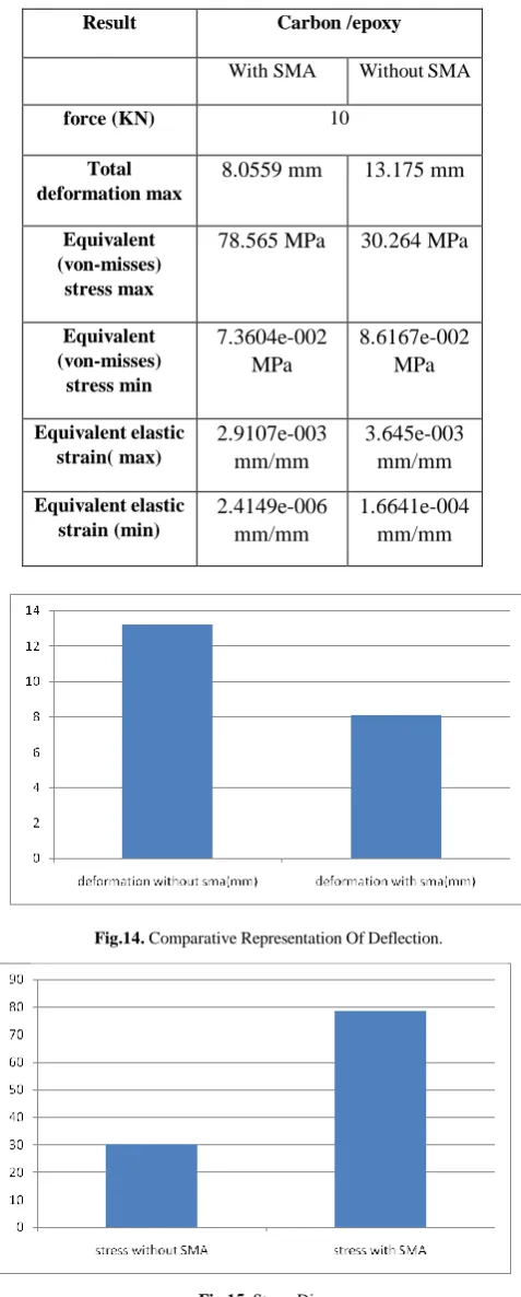
Several results are available after simulation of the carbon/epoxy
beam with and without SMA by using 10% of SMA by volume. The
main focus was on the total deformation, equivalent (von-misses)
stress and elastic strain.
Results obtained are as
follows:-Fig.10. Total Deformation Without SMA.
Fig.8. Equivalent Stress Without Shape Memory Alloy
Fig.9. Equivalent elastic strain without SMA
Fig.11. Equivalent
stress with sma
Fig.12. Equivalent Elastic Strain With SMA
Table 3. The Result Are As Follows
Result
Carbon /epoxy
With SMA
Without SMA
force (KN)
10
Total
deformation max
8.0559 mm
13.175 mm
Equivalent
(von-misses)
stress max
78.565 MPa
30.264 MPa
[image:4.595.53.292.72.666.2]Equivalent
(von-misses)
stress min
7.3604e-002
MPa
8.6167e-002
MPa
Equivalent elastic
strain( max)
2.9107e-003
mm/mm
3.645e-003
mm/mm
Equivalent elastic
strain (min)
2.4149e-006
mm/mm
1.6641e-004
mm/mm
Fig.16. Strain Diagram
V.
CONCLUSION
On the basis of the above results, it is concluded that:
1.
The deformation is about half by using the shape
memory alloy wire in the beam.
2.
We will get about more than twice stress by using
shape memory alloy wires.
3.
The strain is reduced by 1.25 times by using SMAs
wires in the carbon/epoxy beam.
In future work, we are increasing the percentage of shape memory
alloy in the top and bottom of the carbon/epoxy beam which
decreases the deformation.
REFERENCES
1. H.,F.(1987). SHAPE MEMORY ALLOY. GORDON AND BREACH SCIENCE
PUBLISHERS .
2. S.M.R. KHALILI, M.D.(2013). MODELING AND TRANSIENT DYNAMIC
ANALYSIS OF PSUDOELASTIC SMA HYBRID COMPOSIITE BEAM. APPLIED
MATHEMATICS AND COMPUTATION .
3. YAHYA BAYAT,H.E.(2019). A NON LINEAR STUDY ON STRUCTURAL
DAMPING OF SMA HYBRID COMPOSITE BEAM. THIN WALLED STRUCTURE ,
18-28.
4. ANSYS Mechanical APDL Structural Analysis guide & ANSYS Reference Guide.
5. Brinson LC, Lammering R.Finite elemant analysis of the behavior of Shape memory alloy and their applications,Int J Solid Struct 1993;4;229-242
6. Bathe K-J. Finite Element Procedures, Cambridge University Press: 2007. 7. Zhu S,Zhang Y.A Thermomechinical Constitutive Model For Superelacticity SMA Wire With Strain- Rate Dependence. Smart Materialstructure 2007;16:1696-707
8. B.T. Lester, T. Baxevanis, Y. Chemisky, D.C. Lagoudas, Review and perspectives: shape memory alloy composite systems, Acta Mechnica 226 (2015) 3907–3960.
9. Y. Bayat, H. EkhteraeiToussi, Exact solution of thermal buckling and post buckling of composite and SMA hybrid composite beam by layerwise theory, Aerosp. Sci. Technol. 67 (2017) 484–494.
10. S. Hassanli, B. Samali, Buckling analysis of laminated composite curved panels reinforced with linear and non-linear distribution of shape memory alloys, ThinWalled Struct. 106 (2016) 9–17.
11. S.M.T. Hashemi, S.E. Khadem, Modeling and analysis of the vibration behavior of a shape memory alloy beam, Int. J. Mech. Sci. 48 (2006) 44–52.
12. FINITE LEMEMT ANALYSIS THEORY AND APPLICATION WITH
13. Ansys,Third Edition ,Pearson Education,Inc,2008
Fig.14. Comparative Representation Of Deflection.
AUTHORSPROFILE
Yatendra Saraswat Mtech student, GLA University, Mathura (India) has earned his B.Tech from A.K.T.U, Lucknow
.
Sangam Yadav M.tech student, GLA University, Mathura (India) has earned her B.Tech from HCST, Mathura AKTU Lucknow U.P. (India). She has presented a paper in International Conference.