Graphic programming by elements of
nonstandard structural forms
Vsevolod Chugreyev1, Vadim Kaikov1, and Tatiana Kapitonova1*
1 Saint Petersburg State University of Architecture and Civil Engineering, Faculty of Economics and Management, 190005 2-ya Krasnoarmeiskaya st. 4, Russia
Abstract. The article describes one of the variants for solving the actual practical problem on information building modeling with application of several computer programs. The authors showed the relationship between graphic programming and model parameterization using specifications. The main purpose of the work was to show the algorithm for designing an architectural and construction object from the choice of the conceptual form to obtaining the information required for the industrial production of parts. The authors note the importance of studying similar problems in the framework of training courses of architecture and civil engineering universities.
Good design methods are in desperate need of processes automation. Hand labor facilitation by computers allows creating more and more geometrically complex forms. However, as we know, it is not enough to create a new form, it is required to form its cutting, to provided with the necessary information, to bring it to the machine. The relationship between project and production is a very important BIM component in the world practice. [1] The only way to keep up with the times is to learn, perfect and create new automation technologies [2].
One of such tasks is the implementation of architectural design solutions with complex glazing. An incredibly defused environment of professionals in this field takes place despite of the great interest in these forms in the Russian-language information space.
In Saint Petersburg, the Lakhta-Center is an example of the Russian specialists’
achievement presenting the complex shell cutting that is shown in Fig. 1 [3].
Fig. 1. A fragment of the Lakhta-Center glazing (ZAO GORPROJECT, Revit and Grasshopper units) [4]
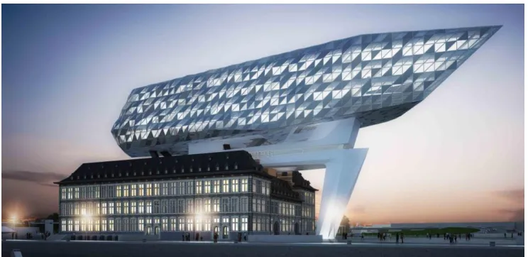
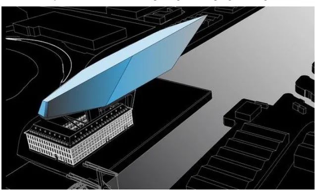
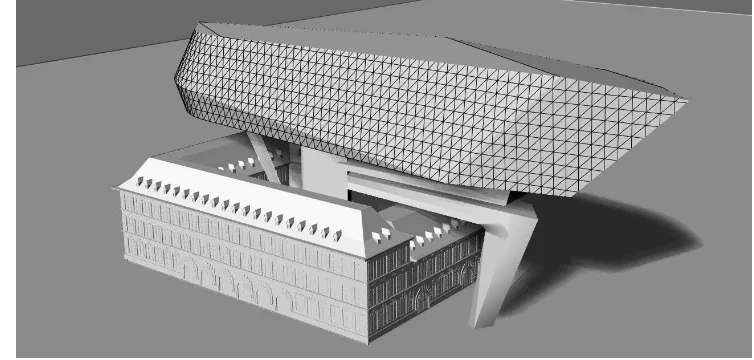
We are interested in non-standard (non-rectangular) cutting of panels in one of the modern buildings constructed based on the project of bureau Zaha Hadid Architects (Fig.2).
Fig. 2. Port Authority Building in Antwerp (Zaha Hadid Architects)
(http://clipgoo.com/daut/as/f/t/the-wonderful-zaha-hadid-architect-buildings-cool-design-ideas- 3369_amazing-interior-architectural-buildings-images_interior-design_interior-design-salary-designer-san-antonio-job-description-internsh.jpg)
The upper part of the building is a free form glazed with triangular panels, the tangible embodiment of which is associated with a large number of similar elements (glazing panels and imposts) with geometric differences, and thus requiring the process design flexibility. The existence of such projects basically became possible due to the programming of graphic objects with receiving the specifications sent to an automated production.
[image:2.482.56.428.270.451.2]Fig. 1. A fragment of the Lakhta-Center glazing (ZAO GORPROJECT, Revit and Grasshopper units) [4]
We are interested in non-standard (non-rectangular) cutting of panels in one of the modern buildings constructed based on the project of bureau Zaha Hadid Architects (Fig.2).
Fig. 2. Port Authority Building in Antwerp (Zaha Hadid Architects)
(http://clipgoo.com/daut/as/f/t/the-wonderful-zaha-hadid-architect-buildings-cool-design-ideas- 3369_amazing-interior-architectural-buildings-images_interior-design_interior-design-salary-designer-san-antonio-job-description-internsh.jpg)
The upper part of the building is a free form glazed with triangular panels, the tangible embodiment of which is associated with a large number of similar elements (glazing panels and imposts) with geometric differences, and thus requiring the process design flexibility. The existence of such projects basically became possible due to the programming of graphic objects with receiving the specifications sent to an automated production.
The development of computer hardware and software at the present stage creates the need to organize the fullest possible use of these resources, and requires establishing the relations between the original idea and the ultimate embodiment of the plan. In addition, the computer model can identify in advance the inconsistencies and deviations of the project, investigate the object behavior in different conditions (seismic, weather, etc.), identify the impact on the environment and people habitat, and make corrections with minimal financial costs.
The purpose of programming is the compilation of such algorithms that could be used for solving various problems, in this case architectural design.
Not every architect should and can be a graphic programmer. This is absolutely not necessary. As applied to our task, it is sufficient for him to know that the form to be designed as glazed can be implemented using the ready algorithm. The graphic programmers are a special type of modern architects who have a set towards mathematics and can shift hand labor to the computer systems.
The design of structural glazing of complex forms is a chain of actions for creating and cutting a surface, forming a points array, creating an adaptive element, and adapting each element to the points array. This chain of actions can take various forms, extending and shortening depending on the task complexity.
The factor ensuring a significant part of the success is the right choice of software. For the wide distribution of graphic programming, it is important that software products are not only available, but also available to different layers of users.
The software choice is determined for us by the following requirements:
The form-designing geometry format: if the exact proportions of the object do not fully "fit" or are dependent on each other, then it is necessary to refer to the method of visual programming, otherwise, when the form-designing elements are unambiguous and unchangeable, it is possible not to parametrize the form-designing element;
A variety of form-designing tools and visibility of their operation.
[image:3.482.57.427.331.509.2]After the available computer resources have been analyzed, we fixed on the software shown in Fig.3.
Fig. 3. Interrelations of the selected software.
Then we will present a program that automates the process of dividing the surface into structural elements (triangles) and drawing up specifications for their glazing and imposts.
Lets choose a surface formed by lofting through three profiles of open curves of different curvature as the simplest curvilinear form. Upon completion of the form development, it is necessary to place it in the Revit environment from other ones. The imported form must have an extension of sat.
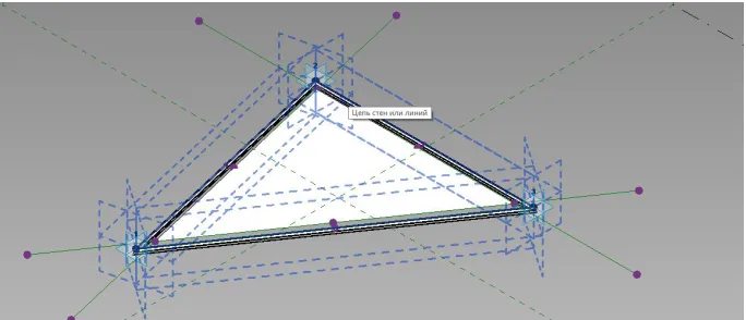
the form with ten panels, each of which will be based on six points, we will have to get a list of ten lists for six elements, each of which will be the coordinates of the adaptive point of the structural element [5].
Fig. 4. The simplest partitioning of a test form in the Revit.
In case of Dynamo, the points grid reference is transmitted directly through the node "adaptive component by points", to which the list of these points will be provided, and in case of Grasshopper, the list of points will have to be transmitted via the Grevit plug-in, which will be installed both on the Grasshopper and on Revit.
A general parameters file is created in the project to create the specifications for the structural system elements. Adaptive points are created in the family file. The geometry is parametrized based on these adaptive points. It is recommended that all the set parameters are common, so that they can be read and marked. As much as possible, it is recommended to express the parameters through each other using the mathematical formulas. This will result in the more correct calculation and the possibility for complete exclusion of physical geometry to facilitate the model.
For further parameterization, it is necessary to create the specifications for materials and elements by selecting the adaptive families through the category "generalized models". The created specifications will allow reducing all the parameters generated by the structural elements to a single list that will be exported to Excel for further processing or linked to Excel by means of Dynamo or Flux.
It should be understood that the above method is very conditional and does not disclose all the design fundamentals. Any problem is complicated when a number of input data increases. Sometimes there are cases when the slightest missed condition that is not taken into account in the script will require its complete replacement.
However, in general, the factors that complicate the problem solution can be classified according to the following points:
a) Computing – increasing an amount of computation which can cause complications in the geometry calculation. Problems of this kind may require the optimization of the script
structure.
b) The form composite character when the form is created from several surfaces which can not be represented as a single solid one. The form composite character can significantly complicate the process of form division since the cases of mismatching the breakdown grids are possible, and they can disturb the aesthetics and function of the structure to be formed.
c) The nature of the starting form. An improper format of the starting form can significantly complicate the breakdown process since it will require data conversion or even make a correct breakdown impossible in no circumstances.
d) Increasing the details of the adaptive structural element. This parameter can significantly affect the problem complexity since it will require more time both to develop the structural element itself and to develop a script controlling its location.
e) Application of unofficial "combined" nodes in the script body can complicate the problem, as it does not guarantee its correct operation.
The problem contains a complex form, the volume of which shall necessarily be adaptive. This means that it is not enough to use only the Revit and Dynamo environments to solve the problem. It is required to apply the Rhinosceros and Grasshopper.
The historical part of the building was exported to the Rhino environment. It should be noted that the export shall be configured in the DWG format so that Revit does not convert the original NURBS geometry to the MESH format and also does not export excess parts of the building which do not influence the aesthetics of the formation of the global volume of the building.
[image:5.482.82.400.344.537.2]A sketch form design is to work with the standard Rhino tools (Fig. 5). After the form is found, it is necessary to think in advance the principle of its programming and division.
Fig. 5. A sketch form design in the Rhino.
The sequence of basic geometry formation:
1. A point with three variable coordinates will be the basis of the studied form;
2. Formation of other three points of the rectangle by adding an additional value of x and y coordinates to the starting X and Y coordinates;
3. Rectangle formation by connecting the points with straight lines;
5. Parametrization of the automatic rotation of points through an angle formed by two opposite points and the X axis, and it provides automatic alignment of the form so that with changing its dimensions one pair of opposite points is always able to form a segment parallel to the orthogonal axis of the building;
6. Formation of a closed polyline by successively joining points and formation of a surface that lies within the closed polyline;
7. Surface extrusion along the vector.
Thus, we obtain the simplest form, further actions with which can be compared with faceting that means successive cutting of the form parts by planes based on three points, each of which is parametrized on the form edges. Here it is necessary to track the direction of the plane normal line that shall always be fixed toward the form part to be cut.
It should be noted that the grid is continuous on the form bends. This continuity is achieved through the interaction of an inclined forms and three rows of sectional planes. Three uniform rows of sectional planes – 0, 45 and 90 degrees form a triangle with the intersection of any edge.
The next action is used to break the grid by the resulting continuous lines onto three-, four- and five-sided surfaces. For this purpose, it is necessary to check the surface grid interaction by selecting the lines as per the belonging of a certain surface. For this action, the Surface Closest Point node was used that determined a distance from the point lying in the middle of the curve to the planes, and then by the filtering method, that is zero values selection from non-zero ones was done using the Dispatch node. Thus, we compared all grid lines with all edges and filtered the lists so that the surface indices coincided with the line ones belonging to this surface.
[image:6.482.49.426.385.565.2]After obtaining the correspondence of the indices of both lists, it is necessary to bring both lists to the Surface Split node that will separate certain planes with the corresponding lines. The result will be the formation of separated surfaces which are the basis for the panels (Fig. 6).
Fig. 6. The summary file in Rhino with correct grid.
It is necessary to consider the boundary points from the resulting surfaces. For this purpose the Deconstruct Brep node, shall be used that allows obtaining the geometry apexes. Now it is required to consistently perform three operations:
5. Parametrization of the automatic rotation of points through an angle formed by two opposite points and the X axis, and it provides automatic alignment of the form so that with changing its dimensions one pair of opposite points is always able to form a segment parallel to the orthogonal axis of the building;
6. Formation of a closed polyline by successively joining points and formation of a surface that lies within the closed polyline;
7. Surface extrusion along the vector.
Thus, we obtain the simplest form, further actions with which can be compared with faceting that means successive cutting of the form parts by planes based on three points, each of which is parametrized on the form edges. Here it is necessary to track the direction of the plane normal line that shall always be fixed toward the form part to be cut.
It should be noted that the grid is continuous on the form bends. This continuity is achieved through the interaction of an inclined forms and three rows of sectional planes. Three uniform rows of sectional planes – 0, 45 and 90 degrees form a triangle with the intersection of any edge.
The next action is used to break the grid by the resulting continuous lines onto three-, four- and five-sided surfaces. For this purpose, it is necessary to check the surface grid interaction by selecting the lines as per the belonging of a certain surface. For this action, the Surface Closest Point node was used that determined a distance from the point lying in the middle of the curve to the planes, and then by the filtering method, that is zero values selection from non-zero ones was done using the Dispatch node. Thus, we compared all grid lines with all edges and filtered the lists so that the surface indices coincided with the line ones belonging to this surface.
After obtaining the correspondence of the indices of both lists, it is necessary to bring both lists to the Surface Split node that will separate certain planes with the corresponding lines. The result will be the formation of separated surfaces which are the basis for the panels (Fig. 6).
Fig. 6. The summary file in Rhino with correct grid.
It is necessary to consider the boundary points from the resulting surfaces. For this purpose the Deconstruct Brep node, shall be used that allows obtaining the geometry apexes. Now it is required to consistently perform three operations:
1. Unify the geometry and delete the matching points, that is, if a distance between points is less than a certain value, then several points become one with the averaged coordinate. 2. Classify the geometry from three, four and five points in different lists.
3. Change the numbering of points in a single order (clockwise or counter-clockwise) and, possibly, divide the staggered panels into different lists.
Then these data shall be sent to the Grevit plug-in node, having converted the dimensions before. Three nodes will be in total, each node will be responsible for one of the three elements. The names of the respective families shall be provided at the entrance to these nodes.
The adaptive component programming in Revit is reduced to three families, one for each of the resulting types of glazing.
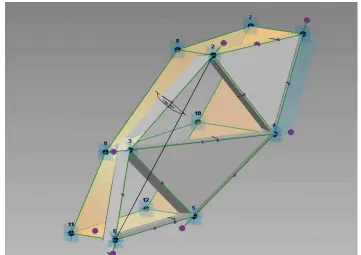
[image:7.482.71.413.200.347.2]The adaptive framework creation means the formation of three adaptive points and the lines reference to them. These lines will be a peculiar axes. The geometry of the imposts and glasses will be referenced to these lines (Fig. 7).
Fig. 7. An example of the family based on three points.
It is recommended to make the imposts profile by a separate family developed and based on the template "Metric system. The family based on an edge." The glass plane like the imposts profile shall be referenced to the axial lines shifted to the center by a certain indent. This is resulted from the peculiarity of the modular glazing [6]. For the reason that the impost profile will be formed by an nested family, it should also be remembered that the parameters of the nested family shall be repeatedly referenced to the parameters of the main family.
The specifications shall be common to provide reading the family parameters by the Revit specifications. For this purpose, create a general parameters file in the project menu; the file contains the names of all the required parameters.
Most parameters are preferable to be determined not by the method of filling up the parameters for reports on the object geometry, but by the method of formulas creation in the menu of family sizes. Formulas creation helps to avoid deleting the parameter marks when errors occur [7].
The next step is location of the geometry with the Grevit plug-in, the feature of which is that it forms a unique link of two programs allowing to implement forms in the Revit without the Dynamo. The plug-in is simultaneously installed on both software – the Grevit plug-in activation key is pressed in the Revit. Further, after pressing the activation key that is suitable for the Grevit node, the data from Grasshopper is sent to the Grevit nodes and on their basis the Grevit builds the geometry in the Revit.
We created a file of common parameters in order to be able to reduce them to the specification as per the category "Generalized models".
There is nothing paradoxical that the environment of form-designing in the Revit is well suited for the formation and parametrization of a structural element, but it is not suitable for rapid and free form-designing. Visual objects parameterization requires the sequence and logic for object creation, and this fact, in turn, is very contrary to the problem of quick and free generation of any free form. The transition from one modeling environment to another is always very abnormal since it requires good knowledge of the interface of both environments.
The absence of the required nodes.
The nodes limitation in the programming language results in an inefficient, stretched script form. Here it can be noted that there are ways to add the nodes in different programming languages.
Resource efficiency of the node programming.
A way to form the grid by splitting the geometry by the Surface Split node is very functional and user-friendly, however, it is quite resource-consuming for the computer. However, these parametric objects would be impossible in principle to create usual methods of "manual" modeling.
Human factor.
Despite the fact that parametric shaping has been existing for several decades, people who are at the intersection of programming and design remain very few. A consequence of this fact is the slow development of tools and functionality of software application.
Globally, the applied methods are out of date together with the outdated programs through which we address them. The most important thing is to understand the program operation principles which will lead to complete success, or limitation at any stage.
The modeling by means of the nodes has one essential feature: being between the programming and the design, it completely blurs the framework between these concepts, increasingly expands the thinking space, deviating an architect from the primary task of "creating the quality object" to the more primary task of "developing the method for creating the quality object” or even "developing the qualitative method for creating the quality object". This violation of the primary meaning creates serious psychological discomfort for a designer. However, this is only a prelude to the problems of the future world, and only a few of people can predict them.
The authors are convinced that if the paper is competently popularized with these methods, in the future we will be able to get professionals of a new level who will be able to understand the BIM both in terms of the tools and the holistic way of thinking [8]. These professionals will be able to bring the market of Russian architecture to a new digital level as they will never have the question "how can this be created?”
The market requires more specialists at the intersection of programming and design. Now these competences can no longer be based on personal contacts and ambitions. The state itself shall take the BIM-training initiative. The new opportunities [9] that will be provided by these technologies will help create career benefits [10] for university students, reinforcing their interest in the BIM-technologies development. This problem exists not only in Russian, but also in foreign practice [11], and it shall be solved comprehensively starting from the school bench – wide application of graphic design methods to form the required way of thinking and applied skills.
References
1. F. H. Abandaa, J. H. M. Taha, F. K. T. Cheungb, Journal of Building Engineering, 14 (2017)
2. Seok-heon Yun, Ki-hyun Jun, Chang-baek Son, and Sang-chul Kim, Journal of Civil Engineering, 18 (2) (2014)
3. Lakhta Center [online], Available at: https://www.youtube.com/channel/UCHFGjNnM
E5T8w1zEKzchdZQ (2018)
4. Albert Sumin from Gosprojekt on Grasshopper and Dynamo [online], Available at: https://digitalgipsy.org/2016/01/11/albert-sumin/ (2016)
5. The website of the multi-field research and consulting agency Bureau Bouwtechniek that specializes in building technologies [online], Available at: http://b-b.be/en/portfolio/new-port-house/ (2018)
6. Geektimes [online]. Available at: https://geektimes.ru/company/lakhtacenter/blog/2840 82/ (2018)
7. Autodesk official website [online], Available at: https://www.autodesk.ru/campaigns/aec-building-design-bds-new-seats/landing-page
(2018)