UNIVERSITI TEKNIKAL MALAYSIA MELAKA
DEVELOPMENT OF SOLAR TRACKER USING
MICROCONTROLLER TO CONTROL
STEPPER MOTOR
This report is submitted in accordance with the requirement of the Universiti Teknikal Malaysia Melaka (UTeM) for the Bachelor of Electronic Engineering Technology
(Industrial Electronics) with Honours.
by
STUDENT NAME: SITI KHOTIJAH BINTI SELAMAT MATRIX NUMBER: B071410653
IC NUMBER: 920312065260
UNIVERSITI TEKNIKAL MALAYSIA MELAKA
BORANG PENGESAHAN STATUS LAPORAN PROJEK SARJANA MUDA
TAJUK: Development of Solar Tracker Using Microcontroller to Control
Stepper Motor
SESI PENGAJIAN: 2016/17 Semester 2
Saya SITI KHOTIJAH BINTI SELAMAT
mengaku membenarkan Laporan PSM ini disimpan di Perpustakaan Universiti Teknikal Malaysia Melaka (UTeM) dengan syarat-syarat kegunaan seperti berikut:
1. Laporan PSM adalah hak milik Universiti Teknikal Malaysia Melaka dan penulis. 2. Perpustakaan Universiti Teknikal Malaysia Melaka dibenarkan membuat salinan
untuk tujuan pengajian sahaja dengan izin penulis.
3. Perpustakaan dibenarkan membuat salinan laporan PSM ini sebagai bahan pertukaran antara institusi pengajian tinggi.
4. **Sila tandakan ( )
SULIT
TERHAD
TIDAK TERHAD
(Mengandungi maklumat yang berdarjah keselamatan atau kepentingan Malaysia sebagaimana yang termaktub dalam AKTA RAHSIA RASMI 1972)
(Mengandungi maklumat TERHAD yang telah ditentukan oleh organisasi/badan di mana penyelidikan dijalankan)
Alamat Tetap:
Lot 10, Kampung Bunian,
28100 Chenor, Pahang. Tarikh: ________________________ Disahkan oleh: Cop Rasmi: Tarikh: _______________________
DECLARATION
I hereby, declared this report entitled “Development of Solar Tracker Using Microcontroller to Control Stepper Motor” is the results of my own research except as
cited in references.
Signature :………..
Author’s Name :SITI KHOTIJAH BINTI SELAMAT
APPROVAL
This report is submitted to the Faculty of Engineering Technology of UTeM as a partial fulfillment of the requirements for the degree of Bachelor’s Degree in Electronics Engineering Technology (Industrial Electronics) with Honours. The member of the supervisory is as follow:
……… ENCIK EFFENDY ONN BIN SIAM
i
ABSTRAK
ii
ABSTRACT
iii
DEDICATION
iv
ACKNOWLEDGEMENT
v
TABLE OF CONTENT
Abstrak i
Abstract Ii
Dedication iii
Acknowledgement iv
Table Of Content v-vii
List Of Table viii
List Of Figure ix-x
List Of Abbreviations, Symbols And Nomenclature xi
CHAPTER 1:INTRODUCTION 1-4
1.1 Project background 1
1.2 Objective of the project 2
1.3 Project scope 3
1.4 Problem statement 3-4
CHAPTER 2: LITERATURE REVIEW 5-28
2.1 Solar tracker overview 5-6
2.2 The Earth: Rotation and revolution 6-8
2.3 Solar irradiation: Sunlight and the solar constant 8-9
2.4 Sunlight 9-11
2.4.1 Elevation angle 2.4.2 Zenith angle 2.4.3 Azimuth angle
10 10 11 2.5 Types of solar trackers and tracking technologies 11-16
2.5.1 Active tracker 2.5.2 Passive tracker
2.5.3 Differentiate of different technologies in solar trackers 2.5.4 Single axis tracker
2.5.5 Dual axis tracker
2.5.6 Advantages single axis over dual axis of tracker technologies 12 12 13 13-14 14 14-16
2.6 Light dependent resistor theory 16-19
2.6.1 The concept by using two LDRs
2.6.2 Design of light sensor 17-18 18-19
2.7 Stepper motor 19-22
2.7.1 How the stepper motor is controlled
2.7.2 Advantages and disadvantages of stepper motor 21 22
vi
2.9 Voltage regulation 23-24
2.10 Microcontroller 25-26
2.11 Merits and demerits of solar energy 27
2.11.1 Merits of solar energy
2.11.2 Demerits of solar energy 27 27
2.12 Summary of literature review 28
CHAPTER 3: METHODOLOGY 29-52
3.1 Project Planning 29-31
3.2 Overview of the project 32
3.3 Project Flowchart 33-36
3.4 Design and development of the project system 37-41
3.4.1 Software and Hardware Testing 37-38
3.4.2 Result and analysis from solar panel 38-41
3.5 Software implementation 42
3.5.1 Simulation in Proteus Software 42-44
3.5.2 MikroC PRO for PIC Software (Compiler) 44-49
3.5.2.1 Calculation of battery 45
3.5.2.2 C Program Development 45-49
3.6 Hardware Model development (Assembly) 50-52
3.6.1 PCB Development 50
3.6.2 Hardware Development 51
3.6.3 Component Testing 51-52
CHAPTER 4: RESULT AND ANALYSIS 53-64
4.1 Software and Hardware Testing 53-54
4.2 Result and analysis from solar panel 54-61
4.2.1 Current and power observation on first day 56-58 4.2.2 Current and power observation on second day 59-61
4.3 Result Observation 61
4.4 Hardware development result 62
4.5 Discussion 63
CHAPTER 5: CONCLUSION AND RECOMMENDATION 65-66
5.1 Conclusion 65-66
`5.2 Recommendation 66
REFERENCES 67-68
APPENDICES 69-74
A Data Sheet PIC18F 69
vii
C Stepper Motor Wiring Diagram 72
D LM7805 73
viii
LIST OF TABLES
2.1 Table 2.1: Range for sunlight brightness in unit (lux) 10 2.2 Table 2.2: Merits and demerits solar tracker 13 2.3 Table 2.3: Advantage of development solar trackers 14-16 2.4 Table 2.4: Value of resistance based on the light intensity 19
3.1 Gantt Chart for PSM 1 30
3.2 Gantt Chart for PSM 2 31
3.3 Selection of mechanical part 37
3.4 Component and materials name with description 39 3.5 Component and materials name with description 45
4.1 Comparison of Fixed Panel and Single Axis of Solar Trackers Day 1
56
4.2 Comparison of Fixed Panel and Single Axis of Solar Trackers Day 2
59
ix
LIST OF FIGURE
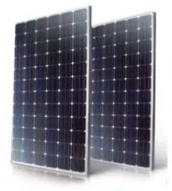
2.1 Solar Panel 6
2.2 The rotation of Earth’s 7
2.3 Earth’s rotation and revolution 8
2.4 The angle for zenith, azimuth and elevation 11
2.5 LDR Cadmium sulfide (Cds) 18
2.6 LDR and a resistor in voltage divider circuit 19
2.7 Unipolar stepper motor wiring 21
2.8 Bipolar stepper motor wiring 21
2.9 Connection of crystal circuit 23
2.10 Circuit of Voltage Divider 24
2.11 Pin diagram for LM7805 24
2.12 PIC18F45K22 pin configuration 26
3.1 Main Block Diagram 32
3.2 Flowchart of single axis solar trackers 36
3.3 Simulation on Proteus Software 42
3.4 PCB Layout 43
3.5 Top view of 3D Visualizer 43
3.6 Rear view of 3D Visualizer 44
3.7 Software of mikroC PRO for PIC 44
3.8 Process flow of PCB making 50
3.9 Process of making hardware model 51
3.10 Stages of testing component 51
3.11 PIC board 52
3.12 Hardware model design 52
4.1 Input and output of the microcontroller 54
x
4.3 Panel position at 10.00 AM 55
4.4 Panel position at 12.00 PM 55
4.5 Panel position at 2.00 PM 55
4.6 Panel position at 4.00 PM 56
4.7 Panel position at 6.00 PM 56
xi
LIST OF ABBREVIATIONS, SYMBOLS AND
NOMENCLATURE
PIC - Peripheral Interface Controller LDR - Light Dependent Resister PV - Photovoltaic
HSAT - Horizontal Single Axis Trackers
HTSAT - Horizontal Single Axis Trackers with Tilted VSAT - Vertical Single Axis Trackers
TSAT - Tilted Single Axis Trackers
PSAT - Polar Aligned Single Axis Trackers Cds - Cadmium Sulfide
MCU - Microcontroller Unit AC - Alternate Current DC - Direct Current IC - Integrated Circuit
RISC - Reduce Instruction Set Computer CISC - Complex Instruction Set Computer RAM - Random Access Memory
CPU - Central Processing Unit GND - Ground
1
CHAPTER 1
INTRODUCTION
This chapter is discussed clearly about the project background, objective of the project that have been purpose, project scope and problem statement of the project.
1.1 Project background
2 Solar energy is the energy that more renewable, sustainable and also clean that is in contrast to the gas, oil and coil, and even supporting us to protect our surrounding environment from destruction. Additionally, the solar energy was produced through collecting the sunlight then converts it into electricity power. This can be done by using solar panel, which have large flat panels that made up from many sun cells. Its far most often be utilized in a remote place, although this is becoming more accepted by urban region nicely.
1.2 Objective of the project
1.2.1 To study on the microcontroller (PIC18F) and stepper motor as a controller.
1.2.2 To develop a solar tracker (single axis) that will trace the maximum of the detection of sunlight.
i. To design and as well implement a project that have capable to rotate a stepper motor based on the intensity of the light.
1.2.3 To analysis the optimum energy output (power) from fixed installation panel and solar tracker panel.
3
1.3 Project scope
The scope of this project is to control the rotation of the stepper motor. So, in order to assure the development of this solar tracker be successfully, a well-structured plan must be carried out in this project by searching the detailed concerned. Apart from that, the research must be had careful execution while design and test phase which will transform of the assembly component into a working solar tracker hardware.
1.4 Problem statement
5
CHAPTER 2
LITERATURE REVIEW
This chapter will discuss on approximately of the literature overview and then explain in detailed about the development of solar tracking system, the history of solar panel and overview on the type of solar tracker. In addition, this part also involves the materials that studied and which is relevant to the study. In order to develop this project, it is required to go through a few of research which is related the idea of project that have been purpose. The research will be focusing on hardware and software which to development this solar tracker. The hardware part is included the mechanical part that is need to design in functional prototype. There is a brief on overview of the method used for tracking system and how the system tracks the apparent movement of the sun based on the increasing of power on solar panel. As whole in this chapter is about the basic knowledge on making solar tracking system.
2.1 Solar tracker overview
6 need to add to the system. The solar panel converts visible light into direct current because it is semiconductor fabric. If the solar arrays are increased, the efficiencies of solar panel became higher. The photovoltaic energy is which is acquired from the Sun power. A photovoltaic cellular is generally referred to as a solar panel which is the technology that used for conversion of solar energy direct to the electrical power. The photovoltaic cellular is made from silicon alloy which is a non-mechanical device (Algarin, 2016). The cell is the basic construction from block photovoltaic arrangement and a single cell can vary in range 0.5 inches to 4 inches across. Furthermore, a cell only can produce one or two watts which give not enough power for most appliances. So, the performance of the photovoltaic cell system is based on the intensity of sunlight. However, the bad weather like clouds or thick fog indirectly affect the amount of solar power that received by the arrays of photovoltaic which decreased its performance (Kumar, 2013).
Figure 2.1: Solar Panel
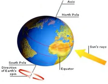
2.2 The Earth: Rotation and revolution
7 Earth axis is an imaginary line which is pass via northern and southern of the Earth poles. The Earth rotation is complete in around 24 hours. The movement was accountable that is incidences of day and night on Earth. However, the 24 hours is term of solar day, while the actual period that sidereal is only 23 hours and 56 minutes. So, the difference is four minutes which is due to the reality the Earth’s position is maintains in changing the reference of the Earth indirect to the Sun.
Figure 2.2: The rotation of Earth’s
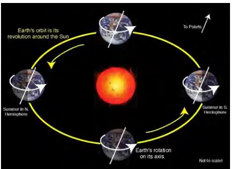
8 Figure 2.3: Earth’s rotation and revolution
2.3 Solar irradiation: Sunlight and the solar constant
The solar grants energy by way of the electromagnetic radiation. There is solar that are fusion which results from the intense temperature and strain of the core of the solar. Protons get converted into helium atoms at six hundred million tons per second. Due to the output of the method has lower strength than the protons that commenced, so fusion gives upward push to masses of power in form of gamma rays which might be absorbed by using particles inside the sun and then they re-emitted. The whole electricity of the solar may be expected by way of the law of Stefan and Boltzmann.
(Dutta, 1990)
T is the temperature which is set 580K and at the same time as r is the radius of the solar that’s 695800 km and Ϭ is the Boltzmann steady that is 1.3806488 x 10⁻²³ m2 kg s-2 k-1.
The emissivity of the floor is denoted by using €. That is because of Einstein’s famous law which is E=mc2 about thousands and thousands of tons of depend are transformed to
9 is the solar radiation which is travels on a straight line from the sun to the surface of the Earth. Whilst diffuse radiation is the description of the sunlight which has been scattered by using debris and molecules inside the surroundings but nonetheless manage to reach the Earth’s floor. The diffuse radiation has no definite path, not like direct versions. Finally, meditated radiation became defined daylight which has been reflected off from non-atmospheric surfaces just like the ground (Cooke, 2011).
2.4 Sunlight