Iteratively Decoded Variable Length
Space-Time Coded Modulation:
Code Construction and Convergence Analysis
Soon Xin Ng,
Member, IEEE, Jin Wang,
Student Member, IEEE, Meixia Tao,
Member, IEEE,
Lie-Liang Yang,
Senior Member, IEEE, and Lajos Hanzo,
Fellow, IEEE
Abstract— An Iteratively Decoded Variable Length Space Time Coded Modulation (VL-STCM-ID) scheme capable of simul-taneously providing both coding and iteration gain as well as multiplexing and diversity gain is proposed. Non-binary unity-rate precoders are employed for assisting the iterative decoding of the VL-STCM-ID scheme. The discrete-valued source symbols are first encoded into variable-length codewords that are mapped to the spatial and temporal domains. Then the variable-length codewords are interleaved and fed to the precoder assisted modulator. More explicitly, the proposed VL-STCM-ID arrangement is a jointly designed iteratively decoded scheme combining source coding, channel coding, modulation as well as spatial diversity/multiplexing. As expected, the higher the source correlation, the higher the achievable performance gain of the scheme becomes. Furthermore, the performance of the VL-STCM-ID scheme is about 14.6 dB better than that of the Fixed Length STCM (FL-STCM) benchmarker at a source symbol error ratio of10−4.
Index Terms— EXIT charts, iterative decoding, MIMO, STTC, VLC.
I. INTRODUCTION
S
HANNON’S separation theorem stated that source codingand channel coding is best carried out in isolation [1]. However, this theorem was formulated in the context of potentially infinite-delay, lossless entropy-coding and infinite block length channel coding. In practise, real-time wireless audio/video communications systems do not meet these ideal hypotheses. Explicitly, the source encoded symbols often remain correlated, despite the lossy source encoder’s efforts to remove all redundancy. Furthermore, they exhibit unequal error sensitivity. In these circumstances, it is often more efficient to use jointly designed source and channel encoders. The wireless communication systems of future generations are required to provide reliable transmissions at high data rates in order to offer a variety of multimedia services. Space
Manuscript received September 14, 2005; revised January 8, 2006; accepted March 9, 2006. The associate editor coordinating the review of this paper and approving it for publication was G. Vitetta. This paper was published in part in S. X. Ng, J. Wang, L.-L. Yang, and L. Hanzo: Variable Length Space Time Coded Modulation, Proceedings of IEEE VTC’05 Fall, Dallas, 26–28 of Sep. 2005, pp. 1049–1053.
S. X. Ng, J. Wang, L.-L. Yang, and L. Hanzo are with the School of Electronics and Computer Science, University of Southampton, SO17 1BJ, UK (e-mail:{sxn,jw02r,lh,lly}@ecs.soton.ac.uk).
M. Tao is with the Department of Electrical and Computer Engineering, National University of Singapore, 4 Engineering Drive 3, Singapore 117576 (e-mail:[email protected]).
Digital Object Identifier 10.1109/TWC.2007.05698.
time coding schemes, which employ multiple transmitters and receivers, are among the most efficient techniques designed for providing high data rates by exploiting the high channel capacity potential of Multiple-Input Multiple-Output (MIMO) channels [2], [3]. More explicitly, Bell-lab’s LAyered Space Time architecture (BLAST) [4] was designed for providing full-spatial-multiplexing gain, while Space Time Trellis Codes (STTC) [5] were designed for providing full-spatial-diversity gain.
The novel contribution of this paper is that we propose a jointly designed source coding and Space Time Coded Modulation (STCM) scheme, where two dimensional (2D) Variable Length Codes (VLCs) are transmitted by ex-ploiting both the spatial and temporal domains. More specifically, the number of activated transmit antennas equals the number of symbols of the corresponding VLC codeword in the spatial domain, where each VLC code-word is transmitted during a single symbol period. Hence, the transmission frame length is determined by the fixed number of source symbols and therefore the proposed Variable Length STCM (VL-STCM) scheme does not exhibit synchronisation problems and does not require the transmission of side information. Additionally, the associated source correlation is converted into an increased minimum product distance1, hence resulting in an
in-creased coding gain. Furthermore, the VL-STCM scheme advocated is capable of providing both multiplexing and diversity gains with the aid of multiple transmit antennas. Practical applications of the proposed scheme are related to the transmission of VLC-based MPEG 2, 3 and 4 encoded video and audio sequences for example. It is also possible to simply pack binary computer-data into VLC-encoded symbols for the sake of their near-capacity transmission.
Relevant work on the joint design of source coding and space-time coding can be found in [6] and [7], where the performance measure is based on the end-to-end analogue source distortion. However, in this paper we assume the presence of a discrete source where the potentially analogue source was quantized/discretized, before it was input to our VL-STCM encoder. Our objective is thus to minimise the error probability of the discrete source symbols. Furthermore, joint detection of conventional one dimensional (1D) VLC and
STCM has been shown to approach the channel capacity in [8], although the related VLC schemes have to convey explicit side information regarding the total number of VLC encoded bits or symbols per transmission frame.
On the other hand, it was shown in [9] that a binary Unity-Rate Code (URC) or precoder can be beneficially concatenated with Trellis Coded Modulation (TCM) [10] for the sake of invoking iterative detection and hence for attaining iteration gains. Since VL-STCM also belongs to the TCM family, we further develop the VL-STCM scheme for the sake of attaining additional iteration gains by introducing a novel non-binary URC between the variable-length space-time encoder and the modulator. The Iteratively Decoded (ID) VL-STCM (VL-STCM-ID) scheme achieves a significant coding/iteration gain over both the non-iterative VL-STCM scheme and the Fixed Length STCM (FL-STCM) benchmarker.
The paper is organised as follows. The overview of the space-time coding technique advocated is given in Section II and the 2D VLC design is outlined in Section III. The description of the proposed VL-STCM and VL-STCM-ID schemes is presented in Sections IV and V, respectively. The convergence of the VL-STCM-ID scheme is analysed in Section VI. In Section VII, the performance of the proposed schemes is discussed and finally our conclusions are offered in Section VIII.
II. SPACETIMECODINGOVERVIEW
Let us consider a MIMO system employing Nt transmit
antennas andNrreceive antennas. The signal to be transmitted
from transmit antenna m,1 ≤m≤Nt, at the discrete time
indextis denoted asxm[t]. The signal received at antennan,
1≤n≤Nr, and at time instantt can be modelled as:
yn[t] =
Es Nt
m=1
hn,m[t]xm[t] +wn[t], (1)
where Es is the average energy of the signal constellation,
hn,m[t] denotes the flat-fading channel coefficients between
transmit antennam and receive antenna n at time instant t,
while wn[t] is the Additive White Gaussian Noise (AWGN)
having zero mean and a variance ofN0/2per dimension. The
amplitude of the modulation constellation points is scaled by a
factor of√Es, so that the average energy of the constellation
points becomes unity and the expected Signal-to-Noise Ratio
(SNR) per receive antenna is given byγ=NtEs/N0[11]. Let
us denote the transmission frame length asT symbol periods
and define the space-time encoded codewords overT symbol
periods as an (Nt×T)-dimensional matrix Cformed as:
C =
⎡ ⎢ ⎢ ⎢ ⎣
c1[1] c1[2] . . . c1[T]
c2[1] c2[2] . . . c2[T]
..
. ... . .. ...
cNt[1] cNt[2] . . . cNt[T]
⎤ ⎥ ⎥ ⎥
⎦ , (2)
where the elements of the tth column c[t] =
[c1[t] c2[t]. . . cNt[t]]T are the space-time symbols
transmitted at time instant t and the elements in the
mth row cm = [cm[1] cm[2]. . . cm[T]] are the space-time
symbols transmitted from antennam. The signal transmitted
at time instant t from antenna m, which is denoted as
xm[t] in Equation 1, is the modulated space-time symbol
given by xm[t] = f(cm[t]) where f(.) is the modulator’s
mapping function. The Pair-Wise Error Probability (PWEP)
of erroneously detectingE instead ofC is upper bounded at
high SNRs by [5], [12]:
p(C→E) ≤ 12
Es 4N0
−EH·Nr
(EP)−Nr , (3)
where EH is referred to as the effective Hamming distance,
which quantifies the transmitter-diversity order and EP is
termed as theeffective product distance[5], which quantifies
the coding advantage of a space-time code.
It was shown in [13], [14] that a full-spatial-diversity STTC scheme having the minimum decoding complexity can be systematically designed based on two steps. The first step is to design a block code, while the second step is to transmit the block code diagonally across the space-time grid. The mechanism of the diagonal transmission across the space-time grid will be exemplified in Section IV in the context of Fig. 2. The Hamming distance and the product distance of a block code can be preserved, when the block code is transmitted diagonally across the space-time grid. Hence, a full-spatial-diversity STTC scheme can be realised, when the Hamming distance of the block code used by the STTC scheme equals to the number of transmitters. Based on the same principle, a joint source coding and STTC scheme can be systematically constructed by first designing a 2D VLC and then transmitting the 2D VLC diagonally across the space-time grid. As mentioned above [14], this allows us to
achieve a transmitter-diversity order2, which is identical to the
Hamming distance of the 2D VLC plus a coding advantage quantified by the product distance of the 2D VLC, as well as a multiplexing gain, provided that the number of possible
source symbolsNs is higher than the number of modulation
levels M. More specifically, the spatial multiplexing gain is
quantified by log2(Ns/M)and the effective information rate
of the scheme is given by η= log2(Ns)bit/s/Hz.
Let us now commence our detailed discourse on the pro-posed VL-STCM-ID scheme in the following sections.
III. TWO-DIMENSIONALVLC DESIGN
Consider for example a source having Ns = 8 possible
discrete values and let thelth value be represented by a symbol
sl=lforl∈ {1,2, . . . , N
s}. Let us consider a source, where
the symbols emitted are independent of each other, but the symbol probability distribution is not uniform and is given by:
P(sl+1) = 0.6P(sl) = 0.6lP(s1), (4)
and Nl=1s P(sl) = 1. Hence, the source symbols1 has the
highest occurrence probability of P(s1) = 0.4068 and the
source symbol s8 has the lowest occurrence probability of
P(s8) = 0.0114. Note that a source is correlated, when its
entropy rate H(s) is smaller than log2(Ns) [15]. For the
independent source considered, the source entropy rate equals
the source entropyH(s), which is given by:H(s) =H(s) =
f
(1) =
−
A
f
(x) = 0
f
(0) =
A
−
A
0
A
A
=
Nt
Lave
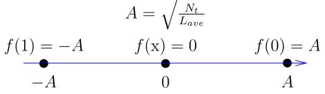
Fig. 1. The signal mapper of the VL-STCM.
−8l=1log2(P(sl))· P(sl) = 2.302 bit. Since H(s) <
log2(Ns), the source considered is a correlated source, where
the higher the source correlation the smaller the source entropy
rate. Let us now consider a 2D VLC codeword matrix,VV LC,
which encodes these Ns = 8possible source symbols using
Nt= 3transmit antennas and BPSK modulation as follows:
VV LC = ⎡
⎣ xx 1x x0 0x x1 1 0 10 1 1
0 x x 1 1 x 1 0
⎤
⎦ , (5)
where each column of the (3×8)-dimensional matrixVV LC
corresponds to the specific VLC codeword conveying a par-ticular source symbol and the elements in the matrix denoted as 0 and 1 represent the BPSK symbols to be transmitted
by the Nt = 3 transmit antennas, while ‘x’ represents ‘no
transmission’. ‘No transmission’ implies that the
correspond-ing transmit antenna sends no signal. Let thelth source symbol
slbe encoded using thelth column of theV
V LC matrix seen
in Equation 5. Hence, the source symbols1 is encoded into
an Nt-element codeword using the first column of VV LC
in Equation 5, namely [x x 0]T, where the first and second
transmit antennas are in the ‘no transmission’ mode, while the third antenna transmits an ‘active’ symbol represented by
the binary value ‘0’. IfL(sl)is the number of ‘active’ symbols
in the VLC codeword assigned to source symbolsl, then we
may define the average codeword length of the 2D VLC as:
Lave = Ns
l=1
P(sl)L(sl), (6)
where we have Lave = 1.233 bit/VLC codeword for this
system according to Equations 4 and 5.
The corresponding BPSK signal mapper is characterised in Fig. 1, where the ‘no transmission’ symbol is actually represented by the origin of the Euclidean space, i.e. we have
f(x) = 0, wheref(.)is the mapping function. Since the ‘no transmission’ symbol is a zero energy symbol, the amount of energy saving can be computed from:
A2= Nt Lave ,
(7)
where we haveA2 = 3/1.233 = 2.433, which is equivalent
to20 log(A) = 3.86 dB. Hence, more transmitted energy is saved, when there are more ‘no transmission’ symbols in a
VLC codeword. Therefore, the columns of the matrixVV LC
in Equation 5, which are the VLC codewords, and the source symbols are specifically arranged, so that the more frequently occurring source symbols are assigned to VLC codewords having more ‘no transmission’ components, in order to save transmit energy. The energy saved is then reallocated to the
‘active’ symbols for the sake of increasing their minimum Euclidean distance, as shown in Fig. 1.
Let us define the Hamming distanceEHminas the number
of different symbol positions of all the columns in the 2D
VLC codeword matrix. Hence, we have EHmin = 2for the
2D VLC codeword matrix in Equation 5. We further define
the minimum product distanceEPmin as:
EPmin = min
1≤s<˜s≤Ns
m∈ξ
|f(vm)−f(˜vm)|2 , (8)
where ξ represents the set of VLC codeword component
indicesmsatisfying the condition of vm= ˜vm for1≤m≤
[image:3.567.34.269.55.123.2]Ntand the VLC codewordv= [v1v2. . . vNt]T is defined in
Fig. 2 and Equation 5. The two VLC codewords conveying the
source symbols s ands˜are represented as [v1. . . vNt]T and
[˜v1. . .˜vNt]T, respectively, in Equation 8. We haveE Pmin=
5.92 based on Equation 5 and the signal mapper of Fig. 1.
Note that the mapper function f(.) used in Equation 8 and
portrayed in Fig. 1 depends on the amount of energy saving. The amount of energy saving is given by Equation 7, where
the numeratorNt is fixed and the denominatorLave is given
by Equation 6. As in the conventional 1D VLC, the higher the source correlation, the lower the average codeword length
Lave of the 2D VLC. A higher energy saving can be attained,
when the source is more correlated due to a reduced average
codeword lengthLave. In other words, the source correlation
is converted into an increased minimum product distance, resulting in an increased coding gain, when the source is more correlated. By contrast, the conventional 1D VLC exploits the source correlation for attaining an increased compression ratio. The design of the 2D VLC scheme can be summarised in the following three steps:
1) Search for all possible VLC codeword matrices, which have the maximum achievable minimum Hamming
dis-tance EHmin and product distance EPmin values for
each pair of the VLC codewords at a given Ns and
Ntcombination. Note that attaining a higherEHmin is
given more weight thanEPmin, since EHmin is more
dominant in the PWEP of Equation 3.
2) Rearrange the columns of the VLC codeword matrices in descending orders according to the number of ‘no transmission’ components. Assign the source symbols to the columns of the VLC codeword matrix, in descending orders according to the symbol probabilities.
3) Find the VLC codeword matrix that gives the shortest average codeword length with the aid of Equation 6. Note that the search-space of step 1 can be significantly reduced with the aid of the branch-and-bound algorithm
of [16], where bothEHmin andEPmin are used during the
bounding operation. By contrast, the code search in [8], [14] also employs the branch-and-bound algorithm, but uses only
EPminin the bounding operation. The 2D VLC matrix seen in
Equation 5 was designed based on the above three steps. When
Nt = 3 transmit antennas are employed for transmitting the
Nt-element 2D VLC codewords denoted asv= [v1. . . vNt]T
in Fig. 2, we achieve a transmitter-diversity order ofEHmin=
2, a coding gain quantified by EPmin = 5.92 and a spatial
multiplexing gain quantified bylog2(Ns/M) = 2, whereM =
Mapper Mapper
Mapper
Mapper Modulator VL−STC Encoder
Encoder
2D VLC S1
S2
s[t]
Sp−q
S3
Sp
p=Nt
j=1(j−1) ; q=Nt−2
vNt[t] v3[t]
v2[t]
v1[t] c1[t]
c2[t] c3[t]
cNt[t]
x1[t] x2[t] x3[t]
xNt[t]
Fig. 2. Block diagram of the VL-STCM transmitter.
modulation and Ns = 8 is the number of source symbols.
The throughput of the scheme is given by η= log2(Ns) = 3
bit/s/Hz and the Signal to Noise Ratio (SNR) per bit is given
byEb/N0=γ/η, whereγ is the SNR per receive antenna.
Based on the above design principles, a range of 2D VLCs
can be created for M-ary PSK modulation for M > 2,
where the origin of the Euclidean space represents the ‘no transmission’ symbol. In general, a VLC code that has the
lowest average codeword lengthLave is attractive in terms of
energy saving (or source compression for 1D VLC). However,
we found that decoding convergence3 could not be achieved
when the minimum Hamming distanceEHmin of the 1D/2D
VLCs equals unity. Hence the tradeoff between energy saving (or source compression for 1D VLC) and decoding gain lies
between minimisingLave and maximizingEHmin. Our goal
is to design a 2D VLC which could help to provide an overall performance approaching the channel capacity, when it is employed in the iteratively detected MIMO system.
IV. VL-STCM SCHEME
The block diagram of the VL-STCM transmitter is illus-trated in Fig. 2, which can be represented by two fundamental blocks, namely the Variable Length Space Time Code (VL-STC) encoder and the modulator. As seen in Fig. 2, a VLC
codeword v[t] = [v1[t] v2[t]. . . vNt[t]]T is assigned to
each of the source symbols s[t] generated by the source at
time instant t, where we have s[t] ∈ {1, . . . , Ns} and Ns
denotes the number of possible source symbols. Each of the
VLC codewords v[t] seen in Fig. 2 corresponds to one of
the columns in the VLC matrix of Equation 5. Hence, the
componentvm[t] of the VLC codeword is represented by a
symbol seen in the VLC matrix of Equation 5. As portrayed
in Fig. 2, the VLC codeword v[t] is transmitted diagonally
across the space-time grid with the aid of appropriate-length
shift registers denoted as Sk in Fig. 2, where we have k ∈
{1,2, . . . ,Nt
j=1(j −1)}. As we can see from Fig. 2, the
codewordv[t] = [v1[t]v2[t] . . . vNt[t]]T is transmitted using
Nt transmit antennas, where the mth element of each VLC
codeword, for 1 ≤ m ≤ Nt, is delayed by (m−1) shift
register cells, before it is transmitted through themth transmit
antenna. Hence, theNt number of components of each VLC
codeword are transmitted on a diagonal of the space-time codeword matrix of Equation 2. Since the VLC codewords
3The convergence analysis of the system will be detailed in Section VI.
TABLE I
THESPACE-TIMECODEWORDTABLE
Index c Index c Index c
0 [ 0 x x ]T 9 [ 0 0 x ]T 18 [ 0 1 x ]T 1 [ 0 x 1 ]T 10 [ 0 0 1 ]T 19 [ 0 1 1 ]T 2 [ 0 x 0 ]T 11 [ 0 0 0 ]T 20 [ 0 1 0 ]T 3 [ 1 x x ]T 12 [ 1 0 x ]T 21 [ 1 1 x ]T 4 [ 1 x 1 ]T 13 [ 1 0 1 ]T 22 [ 1 1 1 ]T 5 [ 1 x 0 ]T 14 [ 1 0 0 ]T 23 [ 1 1 0 ]T 6 [ x x x ]T 15 [ x 0 x ]T 24 [ x 1 x ]T 7 [ x x 1 ]T 16 [ x 0 1 ]T 25 [ x 1 1 ]T 8 [ x x 0 ]T 17 [ x 0 0 ]T 26 [ x 1 0 ]T
are encoded diagonally, the space-time coded symbol cm[t]
transmitted by the mth antenna,1 ≤m≤Nt, at a particular
time-instantt is given bycm[t] =vm[t−m+ 1]. Hence, for
this specific case the transmitted signal is given by:
xm[t] =f(cm[t]) =f(vm[t−m+ 1]), (9)
for1≤m≤Nt. Note that originally there were onlyNs= 8
legitimate 2D-VLC codewords in Equation 5. However, after these VLC codewords are diagonally mapped across the space-time grid using the shift registers shown in Fig. 2, there is a
total of M¯Nt = 33 = 27 legitimate space-time codewords4,
whereM¯ is the number of possible symbols in each position
of the 2D VLC codewords. Note however that the number of legitimate space-time codewords may become lower than
¯
MNt when a different 2D VLC codeword matrix is employed.
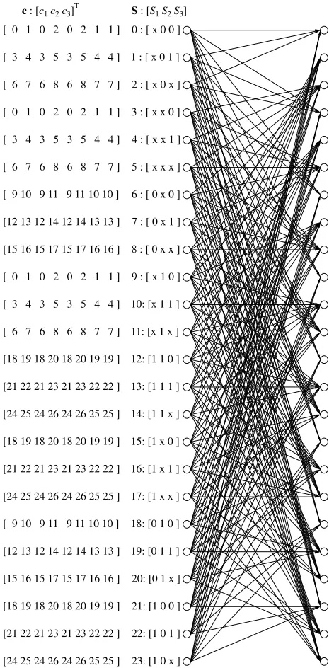
The corresponding trellis diagram of the proposed VL-STC
encoder is depicted in Fig. 3. TheNt= 3-element space-time
codeword seen in Fig. 2 is given by c = [c1 c2 c3]T. The
relationship between the 27 codeword indices shown in Fig. 3
and the space-time codewordcis defined in Table I. The trellis
states are defined by the contents of the shift register cells
Sk shown in Fig. 2, which are denoted byS= [S1 S2 S3].
For example, the state S = 0 is denoted as [x 0 0] in the
trellis diagram of Fig. 3. Note that each shift register cell may
holdM¯ = 3 possible values, namely{0,1,x}in conjunction
with the VL-STC encoder based on Equation 5. However, the
number of legitimate trellis states can be less thanM¯p, where
p=Nj=1t (j−1) = 3 is the total number of shift registers.
Hence, in our specific case there are only 24 legitimate trellis
states out of the M¯p = 27 possible trellis states, which is a
consequence of the constraints imposed by the 2D VLC of Equation 5. As we can see from Fig. 3, there are always
Ns = 8 diverging trellis branches from each state due to
the eight possible source symbols. However, the number of converging trellis paths may vary from one state to another due to the variable length structure of the space-time codewords. Explicitly, there are six and nine trellis paths converging to
stateS= 0and stateS= 1, respectively, as seen in the trellis
structure of Fig. 3.
Similar to the full-spatial-diversity STTC scheme of [14], the above VL-STCM design has the minimum decoding com-plexity required for attaining the target transmitter-diversity and multiplexing gain. On one hand, it is possible to design a range of higher-complexity VL-STCM schemes in order to
4A space-time codeword is defined as theN
c: [c1c2c3] T
S: [S1S2S3] [ 0 1 0 2 0 2 1 1 ] 0 : [ x 0 0 ]
[ 3 4 3 5 3 5 4 4 ] 1 : [ x 0 1 ]
[ 6 7 6 8 6 8 7 7 ] 2 : [ x 0 x ]
[ 0 1 0 2 0 2 1 1 ] 3 : [ x x 0 ]
[ 3 4 3 5 3 5 4 4 ] 4 : [ x x 1 ]
[ 6 7 6 8 6 8 7 7 ] 5 : [ x x x ]
[ 9 10 9 11 9 11 10 10 ] 6 : [ 0 x 0 ]
[12 13 12 14 12 14 13 13 ] 7 : [ 0 x 1 ]
[15 16 15 17 15 17 16 16 ] 8 : [ 0 x x ]
[ 0 1 0 2 0 2 1 1 ] 9 : [ x 1 0 ]
[ 3 4 3 5 3 5 4 4 ] 10: [x 1 1 ]
[ 6 7 6 8 6 8 7 7 ] 11: [x 1 x ]
[18 19 18 20 18 20 19 19 ] 12: [1 1 0 ]
[21 22 21 23 21 23 22 22 ] 13: [1 1 1 ]
[24 25 24 26 24 26 25 25 ] 14: [1 1 x ]
[18 19 18 20 18 20 19 19 ] 15: [1 x 0 ]
[21 22 21 23 21 23 22 22 ] 16: [1 x 1 ]
[24 25 24 26 24 26 25 25 ] 17: [1 x x ]
[ 9 10 9 11 9 11 10 10 ] 18: [0 1 0 ]
[12 13 12 14 12 14 13 13 ] 19: [0 1 1 ]
[15 16 15 17 15 17 16 16 ] 20: [0 1 x ]
[18 19 18 20 18 20 19 19 ] 21: [1 0 0 ]
[21 22 21 23 21 23 22 22 ] 22: [1 0 1 ]
[image:5.567.296.529.53.142.2][24 25 24 26 24 26 25 25 ] 23: [1 0 x ]
Fig. 3. The trellis of VL-STC encoder when invoking the 2D VLC of Equation 5. For the list of codewords see Table I.
attain a higher coding gain. On the other hand, iterative decod-ing is well known for achievdecod-ing near-channel-capacity perfor-mance with the aid of low complexity constituent codes [17]. Hence, we will employ this minimum-complexity transmitter-diversity and multiplexing based VL-STCM arrangment as one of the constituent codes in an iterative decoding scheme.
V. VL-STCM-ID SCHEME
In order to invoke iterative detection and hence attain iteration gains as a benefit of the more meritoriously spread
extrinsicinformation, we introduce a symbol-based random5
interleaver and a non-binary URC for each of the Nt =
3 transmit antennas. The Nt = 3 parallel symbol-based
5The optimumisation of the interleaver is not considered in this paper.
Mapper
Mapper Mapper
Encoder 2D−VLC
D
D
D
D v1[t]
D v2[t]
D v3[t]
x1[t]
x2[t]
x3[t]
c1[t]
c2[t]
c3[t]
VL-STC Encoder Modulator
πs
πs
πs
u1[t]
u2[t]
u3[t]
[image:5.567.33.269.55.527.2]s[t]
Fig. 4. The VL-STCM-ID transmitter employing Nt = 3 transmit and Nr= 2receive antennas, whereπsdenotes symbol interleaver.
VL−STC
MAP
Decoder (3) Demodulator
Demapper Soft
(1) (2.1)
−
− MAP
Decoder
Decoder MAP
πs
π−1
s
ˆ
s[t]
πs
π−1
s
...
L1.1
e (u) L3a.1(c)
L0.1
a (c)
L2.1
e (c)
yNr[t]
y1[t]
˜
c1[t]
˜
u1[t]
L2.1
e (u) L2a.1(c)
L0.1
a (c)
L3.1
e (c)
... ...
(2.Nt)
˜
[image:5.567.297.529.186.285.2]uNt[t] ˜cNt[t]
Fig. 5. The VL-STCM-ID receiver for anNr×Nt MIMO system. The notation (˜.) and (ˆ.) indicates theextrinsic/a prioriprobability and the hard decision estimate of(.), respectively. The notationLi.m(a,e)(c, u)denotes the log-domain symbol probability of the VL-STC codewordcor the URC codeword u for the mth transmitter. The subscripts a and e denote the a priori and extrinsic nature of the probabilities while the superscript i.midentifies that the probabilities belong to the ith stage decoder for the mth transmitter. Note thati= 0means that the probabilities were calculated from the source symbol distribution.
interleavers were generated independently. As we can see
from Fig. 4, each element in the space-time codeword cm[t]
for m ∈ {1,2,3} is further interleaved and encoded by a
non-binary URC, before feeding them to the mapper. The convergence behaviour of the iterative VL-STCM-ID decoder will be analysed in Section VI, where it will be shown that the VL-STCM-ID scheme would be unable to converge at low SNRs, when the recursive feedback assisted non-binary precoders or URCs are not used. By contrast, a simple single-cell non-binary URC invoked before the mapper of each trans-mit antenna would allow us to achieve a significant iteration gain. Hence, the VL-STC encoder was retained unaltered, but the original modulator was modified. The non-binary URC
employs a modulo-M¯ adder, where again, M¯ = 3 is the
number of different symbols in the VLC space-time codeword
and we have cm[t] ∈ {0,1,x}. Accordingly, this single-cell
URC possesses M¯ = 3 trellis states. Note that we represent
the ‘x’ symbol using the number ‘2’ during the
modulo-¯
M addition. Furthermore, the VL-STCM-ID scheme is very
similar to the BICM-ID arrangement proposed in [18], where
N parallel bit-based interleavers were used for interleaving the
bits of the N-bit codeword before the modulator, in order to
attain iteration gains. By contrast, the VL-STCM-ID scheme
employsNtparallel symbol-based interleavers for interleaving
the symbols of theNt-symbol space-time codeword before the
modulator, in order to attain iteration gains with the aid of iterative decoding.
depicted in Fig. 5, where we denote the log-domain symbol
probability of the VL-STC codewordcm and the URC
code-wordum for themth transmitter as Li.m(a,e)(c) andLi.m(a,e)(u),
respectively. Furthermore, the subscriptsa and e denote the
a prioriandextrinsic nature of the probabilities, while the
superscripti.msuggests that the probabilities belong to theith
decoder stage of the mth transmitter. Note that i= 0implies
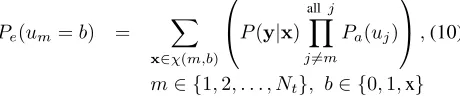
that the probabilities were calculated from the source symbol distribution. The extrinsic probability of the URC codeword
of transmit antenna m, namelyPe(um[t]), can be computed
[image:6.567.46.276.220.269.2]during each symbol period in the ‘Soft Demapper’ block of Fig. 5. By dropping the time-related square bracket, we can
computePe(um)as:
Pe(um=b) =
x∈χ(m,b) ⎛ ⎝P(y|x)
allj j=m
Pa(uj) ⎞ ⎠,(10)
m∈ {1,2, . . . , Nt}, b∈ {0,1,x}
where the subsetχ(m, b)contains all the phasor combinations
for the transmitted signal vectorx= [x1x2 . . . xNt]T where
xm=f(um=b)holds, whileP(y|x)is the Probability
Den-sity Function (PDF) of the MIMO Rayleigh fading channel given by:
P(y|x) = (2 1 πσ2n)Nr
exp
−||y−Hx||2
2σ2
n
, (11)
andσ2n = N0/2 is the noise variance, y is the Nr-element
complex received signal vector, while H is an (Nr×Nt
)-dimensional complex channel matrix during the time instant
t. Furthermore, thea prioriprobability ofumin Equation 10
is computed from theextrinsiclog-domain probability of the
mth URC MAP decoder asPa(um) = exp(L2e.m(u)), while
the log-domaina priori probability ofumfor themth URC
MAP decoder is given by L1e.m(u) = ln(Pe(um)). Hence,
the soft demapper benefits from the a prioriinformation of
its input symbols um after the first iteration. Note that we
employ the Jacobian logarithm [19] to compute Equation 10 in the log-domain, hence there is no need for log-domain to normal-domain conversion. As we can see from Fig. 5, each of
theNt= 3 URC MAP decoders seen inside the demodulator
block benefits from thea prioriinformation of its codeword
um[t] as well as from that of its input symbol cm[t], m ∈
{1,2, . . . , Nt}.
It is possible to attain some a priori probability for the
Nt-element VL-STC codewords, c, (which also constitute
the URC’s input words), given the source symbol occurrence probability specified in Equation 4. Explicitly, the probability
of themth URC’s input wordcmcan be expressed as:
P(cm=d) =
l∈μ(m,d)
P(sl), (12)
m∈ {1,2, . . . , Nt}, d∈ {0,1,x} ,
where the subsetμ(m, d)contains the specific indices of those
columns in the VLC matrix, where themth row element in
that column equalsd. Hence, we haveL0.m
a (c) = ln(P(cm))
as an additionala priori probability for symbol cm during
each iteration between the URC MAP decoder and the
VL-STC MAP decoder, as shown in Fig. 5. Note that P(cm)
is directly computed from the source symbol occurrence
probability P(sl), hence we do not use P(sl) again as the
a prioriprobability of the VL-STC input word in the VL-STC MAP decoder, in order to avoid reusing the same information. Therefore, both the VL-STC and the URC MAP decoders
benefit from the a priori or extrinsic information of the
space-time codewordc[t] = [c1[t]c2[t]c3[t]]T received from
each other as well as from the additionala prioriinformation
provided by the potentially different probability source
sym-bolss[t]. A full iteration consists of a soft demapper operation,
Nt = 3 URC MAP decoder operations and a VL-STC
MAP decoder operation. For the non-iteratively decoded
VL-STCM/FL-STCM, the soft demapper computes the a priori
information of c[t] = [c1[t] c2[t] c3[t]]T and feeds it to the
STCM MAP decoder. Note that the VL-STC/FL-STC decoder of VL-VL-STC/FL-STCM/FL-VL-STC/FL-STCM also benefits from the
a priori probability of its input word s[t], which is given by the source symbol occurrence probability in Equation 4. Hence, as the source becomes correlated, the VL-STCM-ID, VL-STCM and FL-STCM schemes will benefit from the
a priori probability of the source symbols. However, FL-STCM attains no energy savings.
VI. CONVERGENCEANALYSIS
Extrinsic Information Transfer (EXIT) charts designed for binary receivers [20] have been widely used for analysing the convergence behaviour of iterative decoding aided
con-catenated coding schemes. Thenon-binaryEXIT charts were
introduced on the basis of the multi-dimensional histogram computation of [21], [22]. However, the convergence analysis of the proposed three-stage VL-STCM-ID scheme requires the employment of novel three Dimensional (3D) non-binary EXIT charts, which evolved from the binary 3D EXIT charts used in [23], [24] for analysing multiple concatenated codes. To elaborate a little further, EXIT charts visualise the input and output characteristics of the constituent MAP decoders in terms of the mutual information transfer between the input
sequence and the a priori information at the input, as well
as between the input sequence and theextrinsicinformation
at the output of the constituent decoder. Hence, there are two steps in generating an EXIT chart. Firstly, we have to model thea prioriprobabilities of the input sequence and then feed it to the decoder. Secondly, we have to compute the mutual
information of the extrinsic probabilities at the output of
the decoder. Let us now model the a priori probabilities of
the VL-STC codeword, c = [c1 c2 . . . cNt]T, where cm,
m∈ {1,2, . . . , Nt}, is also the input symbol of themth URC.
Let us denote the input symbol of the mth URC as c,
where the subscriptmis omitted for simplicity. Assume that
the symbolc is transmitted across an AWGN channel using
the M= 3-phasor mapper shown in Fig. 1 and the received
signal is given by y =x+n, where n is the AWGN noise
having a zero mean and a variance of σ¯n2. Furthermore, we
have x=f(c), where f(.) is the mapper function portrayed
in Fig. 1. Sincef(.)is a memoryless function, the probability
of occurrence forxis the same as that ofc. Hence, we have
P(x) =P(c), which can be expressed from Equation 12. At a
betweenxandy can be formulated as:
I(x, y) =
M
i=1
y
P(xi, y) log2
P(xi, y)
P(xi)P(y)
dy,
= H(x)−H(x|y), (13)
whereH(x)is the entropy ofx, given by:
H(x) = −
M
i=1
P(xi) log2(P(xi)), (14)
and H(x|y) is the conditional entropy of x given y, which
can be expressed as:
H(x|y) =
M
i=1
P(xi)E ⎡ ⎣log2
⎛ ⎝M
j=1
P(xj)
P(xi)
exp(Ψi,j) ⎞ ⎠ ⎤ ⎦,(15)
where exp(Ψi,j) = P(y|xj)/P(y|xi) and P(y|x) is the
conditional Gaussian PDF, while the exponent Ψi,j is given
by:
Ψi,j= −|xi−xj+n|2+|n|2 2¯σ2
n
. (16)
The expectation term E[.] in Equation 15 is taken over
different representations of the AWGN noise n. Hence, a
curve can be generated for I(x, y) versus σ¯n2, where the
expectation term in Equation 15 is evaluated using Monte Carlo simulation. We can simplify Equation 13 to a form,
whereI(x, y)is expressed as a function ofσ¯2n. Let us denote
this function asJ(.)and we haveI(x, y) =J(¯σn2). Note that
I(x, y)is monotonically decreasing with respect toσ¯2n.
Let us now denote thea prioriinformation ofcasIA(c) =
I(x, y). At a given IA value we can find the corresponding
noise variance with the aid of the inverse function σ¯n2 =
J−1(IA(c)) using the I(x, y) versus σ¯n2 curve. Then we
can generate a noise sample n having a variance of σ¯n2.
Consequently, we can produce y = x+n, where again
x=f(c)represents the mapper function portrayed in Fig. 1
and c is the actual input symbol of the mth URC. Finally,
we can generate the a priorisymbol probabilities forPa(c)
using the conditional Gaussian PDF:
Pa(c) = 1 2πσ¯2
n exp
−|y−f(c)|2
2¯σ2
n
, (17)
forc∈ {0,1,x}. Then we feed these symbol probabilities to
the corresponding MAP decoder. Note that the above method can be used for any symbol-interleaved serially concatenated coding schemes, where the symbol probabilities are directly
created for a given IA value. The mutual information for
the Nt-element VL-STC codeword c = [c1 c2 . . . cNt]T
is the sum of the mutual information valid for its symbol
componentscm, expressed asIA(c) =
Nt
m=1IA(cm), where
IA(cm) is the mutual information of the mth symbol
com-ponent of the VL-STC codeword or the mth URC’s input
symbol, given by Equation 13. Note that the maximumIA(cm)
value equals the entropy ofcmgiven by Equation 14.
Next, we compute the mutual information of the extrinsic
symbol probabilities IE(cm)at the output of the VL-STC or
URC decoder for the symbolcm using the method proposed
in[25], which is computationally more efficient compared
0 1.585
3.17 4.755
x: IEo(URC), IA(Demod) 0
1.5613 3.1226
4.6839
y: IE(VL-STC), IAi(URC)
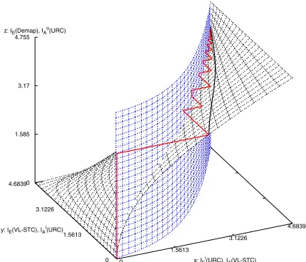
[image:7.567.26.285.60.398.2]0 1.585 3.17 4.755 z: IE(Demod), IAo(URC)
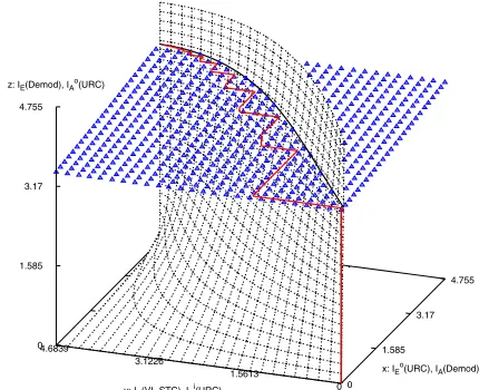
Fig. 6. The 3D EXIT charts for the VL-STCM-ID scheme havingNt= 3
andNr = 2, when using an uncorrelated source. The iterative trajectory is computed atEb/N0 = 4 dB. The maximum value of an axis denotes the entropy of the corresponding symbol.
to [21]. Finally, the mutual information of the extrinsic
symbol probabilities for the VL-STC codeword can be
com-puted from IE(c) =
Nt
m=1IE(cm). We also compute the
mutual information for the URC codeword u based on the
same procedure. However, the experimentally measured PDF
histogram ofuwas found to be near-uniform associated with
equiprobable symbol, when the symbol interleaver length was sufficiently high. This is because the URC employed can be viewed as an accumulator.
The 3D EXIT charts and the actual iterative decoding
trajectories for the VL-STCM-ID scheme havingNt= 3and
Nr = 2 when using an uncorrelated source are shown in
Figs. 6 and 7, respectively. Let us denote the three axes of
the 3D EXIT charts using the letters x, y and z, whileIA(*)
and IE(*) denote the a priori and extrinsic information
for (*), respectively, where (*) is either the VL-STC MAP decoder (VL-STC) or the URC MAP decoder (URC) or, alternatively, the soft demapper (Demod). As we can see from Fig. 5, each of the URC MAP decoders takes (provides) the
a priori (extrinsic) probabilities of its input word c and
output word (or codeword) u as the input (output). Hence,
the mutual information of the input word and output word
of the URC decoder will be represented byI(iA,E)(URC) and
I(oA,E)(URC), respectively. Each of theNtsymbol interleavers
shown in Figs. 4 has a length of 10000 symbols.
The EXIT plane marked with triangles in Fig. 6 was
computed based on the extrinsic probabilities of the soft
demapper L1.m
e (u), for m ∈ {1,2,3}, at the given values
in the x and y axes at Eb/N0 = 4 dB. The other EXIT
plane marked with dashed lines in Fig. 6 is SNR-independent and was plotted based on the URC decoders’ output word
extrinsic probabilities L2.m
e (u), for m ∈ {1,2,3}, at the
[image:7.567.303.518.76.251.2]0
1.5613
3.1226
4.6839
x: IEi(URC), IA(VL-STC)
0 1.5613 3.1226 4.6839
y: IE(VL-STC), IAi(URC)
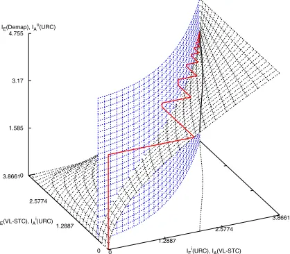
[image:8.567.38.253.71.255.2]0 1.585 3.17 4.755 z: IE(Demap), IAo(URC)
Fig. 7. The 3D EXIT charts for the VL-STCM-ID scheme havingNt= 3
andNr= 2, when using an uncorrelated source. The iterative trajectory is computed atEb/N0 = 4dB. The maximum value of an axis denotes the entropy of the corresponding symbol.
2dprojections.gle
0.0 1.56 3.12 4.68
IE(VL-STC), IAi(URC), IA(Demod) 0.0
1.56 3.12 4.68
IA
(VL-STC),
IE i (URC),
IE
(Demod)
..
..
..
..
. .
. .
. .
. .
. .
. .
. .
. .
. .
Demod URC
.
VL-STCFig. 8. The 2D EXIT charts projection for the VL-STCM-ID scheme having Nt= 3andNr= 2, when using an uncorrelated source atEb/N0= 4dB. The maximum value of an axis denotes the entropy of the corresponding symbol.
L1.m
e (u), L2e.m(u)andLe3.m(c)form∈ {1,2,3}as in Fig. 5,
is under the EXIT plane marked with triangles and on the left of the EXIT plane marked with dashed lines in Fig. 6.
Fig. 7 depicts the 3D EXIT charts, when the x axis of Fig. 6
is changed fromIEo(URC) to IEi(URC). More explicitly, the
vertical EXIT plane seen in Fig. 7, which is independent of the z axis and the SNR, was computed based on the VL-STC
decoder’sextrinsicprobabilitiesL3.m
e (c), form∈ {1,2,3},
at the given values in the x and z axes. The slanted EXIT plane shown in Fig. 7 is also SNR-independent and was
computed based on the URC decoders’ input wordextrinsic
probabilitiesL2.m
e (c), for m∈ {1,2,3}, at the given values
in the y and z axes. The step-wise-linear iterative decoding trajectory displayed in Fig. 7 was plotted based on the extrinsic
probabilitiesL1.m
e (u),L2e.m(c)andLe3.m(c)form∈ {1,2,3}.
According to [24], the intersection of the planes in Fig. 6
represents the points of convergence between the soft demap-per and the URC decoder. The intersection points, where we
have IA(Demod)=IEo(URC) at the corresponding IAi(URC)
and Io
A(URC) values are shown in Fig. 6 as a solid line.
The corresponding values of Ii
E(URC) are shown in Fig. 7
as a solid line on the slanted EXIT plane. Similarly, the intersection of the EXIT planes seen in Fig. 7 represents the points of convergence between the URC decoder and the VL-STC decoder. Hence, by projecting these two intersection curves onto z=0 in Fig. 7 gives us the equivalent 2D EXIT chart seen in Fig. 8. Therefore, the 3D EXIT charts generated for multiple concatenated codes can be projected onto an equivalent 2D EXIT chart [24].
More specifically, we can observe an open tunnel between the EXIT curves of the VL-STC and URC schemes in the 2D
EXIT charts of Fig. 8 at Eb/N0 = 4 dB, which indicates
that decoding convergence can be achieved. However, the URC EXIT curve is SNR dependent and by reducing the
Eb/N0 values the angle between the two curves at the
top-right corner would be further reduced and hence the open tunnel would become closed, hence preventing decoding con-vergence. Therefore, a better URC code may be designed by ensuring that the EXIT curve exhibits a wider angle with respect to the VL-STC EXIT curve. Note furthermore that the EXIT curve generated for the soft demapper is also depicted
in Fig. 8 at Eb/N0 = 4 dB, where it is flat and it intersects
with the VL-STC EXIT curve, before the maximum value of 4.68 bits is reached. Hence, decoding convergence cannot be
achieved at Eb/N0 = 4dB, when the URC was not invoked
between the soft demapper and the VL-STC. Furthermore,
at IE(VL-STC)=0 we have IEi(URC)<IE(Demod). Hence,
[image:8.567.37.270.337.497.2]before any iteration feedback is exploited, the VL-STCM-ID scheme would not outperform its VL-STCM counterpart. It was also concluded in [23] that for a three-stage serially concatenated system a unity-rate recursive encoder, such as the URC used, should be employed at the intermediate stage in order to achieve optimal decoding convergence.
Fig. 9 shows the 3D EXIT charts and the corresponding convergence curve of the soft demapper and the URC decoder as well as the actual iterative decoding trajectory for the
VL-STCM-ID scheme having Nt = 3 and Nr = 2 when
using the correlated source defined in Equation 4. As the
source becomes correlated, the entropy of the codewordcmfor
m∈ {1,2,3} reduces. Hence, the maximum values for the x
and y axes in Fig. 9 are smaller than those in Fig. 7. However, the open spatial segment of the 3D space between the two EXIT planes becomes wider, when the source is correlated,
since the decoders exploit the additionala prioriprobabilities
given by Equation 12. The convergence curve of the soft demapper and the URC decoder is projected as a dashed line
ontoIE(Demod)=0 in Fig. 9. Similarly, the projection of the
intersection line between the VL-STC and URC EXIT planes is represented by the curve lying on the vertical EXIT plane at
IE(Demod)=0. As can be seen from Fig. 9 atIE(Demod)=0,
an open tunnel exist between the two projection curves at
Eb/N0 = 3 dB. Hence, the iterative decoder converged at
Eb/N0 = 3dB, i.e. at a 1 dB lower value, when employing
0
1.2887
2.5774
3.8661
IEi(URC), IA(VL-STC)
0 1.2887 2.5774 3.8661
IE(VL-STC), IAi(URC)
[image:9.567.297.532.55.214.2]0 1.585 3.17 4.755 IE(Demap), IAo(URC)
Fig. 9. The 3D EXIT charts for the VL-STCM-ID scheme havingNt= 3
andNr = 2, when using the correlated source defined in Equation 4. The iterative trajectory is computed atEb/N0 = 3dB. The maximum value of an axis denotes the entropy of the corresponding symbol.
angle between the two projection curves at the convergence point when using the correlated source. A better URC may be designed for an earlier convergence with the aid of the 3D and 2D EXIT charts, but we leave this issue for future research.
According to the MIMO channel capacity formula derived for the Discrete-Input Continuous-Output Memoryless
Chan-nel (DCMC) in [26], the DCMC capacity for the Nr = 2
and Nt = 3 MIMO scheme employing the signal mapper
seen in Fig. 1 isEb/N0= 1.25dB at a bandwidth efficiency
of 3 bit/s/Hz. Hence, the performance of the VL-STCM-ID
scheme is about 2.75 dB and 1.75 dB away from the MIMO channel capacity.
VII. SIMULATIONRESULTS
Let us introduce a Fixed Length (FL) STCM (FL-STCM) scheme as our benchmarker, where the FL Codeword (FLC) matrix is given by:
VF LC = ⎡
⎣ 0 0 0 0 1 1 1 10 0 1 1 0 0 1 1 0 1 0 1 0 1 0 1
⎤
⎦ . (18)
The FL-STCM transmitter obeys the schematic of Fig. 2,
except that it employs theVF LC of Equation 18. For the
FL-STCM, the minimum Hamming distance and product distance are 1 and 4, respectively. It attains the same multiplexing gain as that of the VL-STCM or VL-STCM-ID arrangements. Note that it is possible to create an iterative FL-STCM-ID scheme by replacing the VL-STC encoder in Fig. 4 with the FL-STC encoder. However, the EXIT curve of the FL-STC scheme of Equation 18 was found to be too flat for attaining any iteration gain due to its unity minimum Hamming distance. Let us now evaluate the performance of the STCM, VL-STCM-ID and FL-STCM schemes in terms of their source
Symbol Error Ratio (SER) versus theEb/N0ratio. Again we
stvlc-id2psk-ser-itercwapr-no-dwapr.gle
0 2 4 6 8 10 12 14 16 18 20
Eb/N0(dB)
10-5 10-4 10-3 10-2 10-1 1
SER
Correlated source:
Uncorrelated source: FL-STCM VL-STCM VL-STCM-ID FL-STCM VL-STCM VL-STCM-ID 1 iter.
8 iter.
14.6 dB Capacity
[image:9.567.42.251.73.256.2]Limit
Fig. 10. SER versus Eb/N0 performance of the VL-STCM, VL-STCM-ID and FL-STCM schemes, when communicating over uncorrelated Rayleigh fading channels using BPSK,Nt= 3andNr= 2.
haveEb/N0=γ/η, whereγ is the SNR per receive antenna
and η = log2(Ns) = 3 bit/s/Hz is the effective information throughput.
Fig. 10 depicts the SER versus Eb/N0 performance
of the VL-STCM, VL-STCM-ID and FL-STCM schemes, when communicating over uncorrelated Rayleigh fading chan-nels using BPSK, three transmitters, two receivers and a block/interleaver length of 10000 symbols. As expected, the VL-STCM arrangement attains a higher gain, when the source is correlated compared to STCM. However, the FL-STCM benchmarker also benefits from the probability-related
a priori information of the source symbols, as the source becomes correlated. By contrast, the coding gain attained as a benefit of transmitting correlated source symbols increases, as the number of iterations invoked by the VL-STCM-ID scheme increases. Although the VL-STCM-ID arrangement performs worse than VL-STCM during the 1st iteration, the
performance of VL-STCM-ID at SER= 10−4 after the 8th
iteration is approximately 6.5 (15) dB and 7.5 (14.6) dB better than that of the VL-STCM (FL-STCM) scheme, when employing correlated and uncorrelated sources, respectively. The price of using the VL-STCM-ID scheme for attaining a near-channel-capacity performance is the associated higher decoding and interleaver delay as well as the increased decod-ing complexity. Hence, for a delay-sensitive and complexity-constrained system using VL-STCM is a better choice. By contrast, for a system that requires a higher performance and can afford a higher delay and complexity, VL-STCM-ID should be employed.
VIII. CONCLUSIONS
An iteratively decoded variable length space-time coded modulation design was proposed. The joint design of source-coding, space-time coded modulation and iterative decoding was shown to achieve both spatial diversity and multiplexing gain, as well as coding and iteration gains at the same time. The variable length structure of the individual codewords
mapped to the maximum ofNttransmit antennas imposes no
using 3D symbol-based EXIT charts as well as 2D EXIT chart projections. A significant iteration gain was achieved by the VL-STCM-ID scheme, which hence outperformed both the non-iterative VL-STCM scheme as well as the
FL-STCM benchmarker with the aid of Nt unity-rate recursive
feedback precoders. The VL-STCM-ID scheme attains a near MIMO channel capacity performance. Our future research will incorporate both explicit channel coding and real-time multimedia source codecs.
IX. ACKNOWLEDGEMENTS
The financial support of both the EPSRC, Swindon UK and the EU under the auspices of the Phoenix and Newcom projects is gratefully acknowledged.
REFERENCES
[1] C. Shannon,Mathematical Theory of Communication. Champaign, IL: University of Illinois Press, 1963.
[2] G. J. Foschini, Jr. and M. Gans, “On limits of wireless communication in a fading environment when using multiple antennas,”IEEE Wireless Pers. Commun., vol. 6, pp. 311–335, Mar. 1998.
[3] E. Telatar, “Capacity of multi-antenna Gaussian channels,” European Trans. Telecommun., vol. 10, pp. 585–595, Nov.–Dec. 1999.
[4] G. J. Foschini, Jr., “Layered space-time architecture for wireless commu-nication in a fading environment when using multi-element antennas,” Bell Labs Technical J., pp. 41–59, 1996.
[5] V. Tarokh, N. Seshadri, and A. R. Calderbank, “Space-time codes for high rate wireless communication: Performance analysis and code construction,”IEEE Trans. Inform. Theory, vol. 44, pp. 744–765, Mar. 1998.
[6] S. Lin, A. Stefanov, and Y. Wang, “Joint source and space-time block coding for MIMO video communications,” inIEEE Veh. Technol. Conf., Sep. 2004, pp. 2508–2512.
[7] T. Holliday and A. Goldsmith, “Joint source and channel coding for MIMO systems,” inProc. Allerton Conf. Commun., Control, Comput., Oct. 2004.
[8] S. X. Ng, F. Guo, and L. Hanzo, “Iterative detection of diagonal block space time trellis codes, TCM and reversible variable length codes for transmission over Rayleigh fading channels,” in Proc. IEEE Veh. Technol. Conf., Sep. 2004, pp. 1348–1352.
[9] D. Divsalar, S. Dolinar, and F. Pollara, “Serial concatenated trellis coded modulation with rate-1 inner code,” inProc. IEEE GLOBECOM, Nov.– Dec. 2000, pp. 777–782.
[10] G. Ungerbo¨ck, “Channel coding with multilevel/phase signals,”IEEE Trans. Inform. Theory, vol. 28, pp. 55–67, Jan. 1982.
[11] A. F. Naguib, V. Tarokh, N. Seshadr, and A. R. Calderbank, “A space-time coding modem for high-data-rate wireless communications,”IEEE J. Select. Areas Commun., vol. 16, pp. 1459–1478, Oct. 1998. [12] D. Divsalar and M. K. Simon, “Trellis coded modulation for
4800-9600 bits/s transmission over a fading mobile satellite channel,”IEEE J. Select. Areas Commun., vol. 5, pp. 162–175, Feb. 1987.
[13] G. Caire and G. Colavolpe, “On low-complexity space-time coding for quasi-static channels,”IEEE Trans. Inform. Theory, vol. 49, pp. 1400– 1416, June 2003.
[14] M. Tao and R. S. Cheng, “Diagonal block space-time code design for diversity and coding advantage over flat Rayleigh fading channels,” IEEE Trans. Signal Processing, pp. 1012–1020, Apr. 2004.
[15] T. M. Cover and J. A. Thomas,Elements of Information Theory. New York: John Wiley, IEEE Press, 1991.
[16] G. L. Nemhauser, A. H. G. Rinnooy Kan, and M. J. Todd,Optimization. Amsterdam, The Netherlands: North-Holland, 1989.
[17] L. Hanzo, T. H. Liew, and B. L. Yeap,Turbo Coding, Turbo Equalisation and Space Time Coding for Transmission over Wireless channels. New York: John Wiley, IEEE Press, 2002.
[18] X. Li and J. A. Ritcey, “Bit-interleaved coded modulation with iterative decoding using soft feedback,”IEE Electron. Lett., vol. 34, pp. 942–943, May 1998.
[19] P. Robertson, E. Villebrun, and P. Höher, “A comparison of optimal and sub-optimal MAP decoding algorithms operating in log domain,” inProc. IEEE International Conf. Commun., pp. 1009–1013, June 1995.
[20] S. ten Brink, “Convergence behaviour of iteratively decoded parallel concatenated codes,”IEEE Trans. Commun., vol. 49, pp. 1727–1737, Oct. 2001.
[21] H. Chen and A. Haimovich, “EXIT charts for turbo trellis-coded modulation,”IEEE Commun. Lett., vol. 8, pp. 668–670, Nov. 2004. [22] A. Grant, “Convergence of non-binary iterative decoding,” inProc. IEEE
GLOBECOM, Nov. 2001, pp. 1058–1062.
[23] M. Tuchler, “Convergence prediction for iterative decoding of three-fold concatenated systems,” inProc. IEEE GLOBECOM, Nov. 2002, pp. 1358–1362.
[24] F. Brannstrom, L. K. Rasmussen, and A. J. Grant, “Convergence analysis and optimal scheduling for multiple concatenated codes,”IEEE Trans. Inform. Theory, pp. 3354–3364, Sep. 2005.
[25] J. Kliewer, S. X. Ng, and L. Hanzo, “On the computation of EXIT characteristics for symbol-based iterative decoding,” in Proc. 4th In-ternational Symposium Turbo Codes with 6th InIn-ternational ITG-Confe. Source Channel Coding, Apr. 2006.
[26] S. X. Ng and Hanzo, “On the MIMO channel capacity of multi-dimensional signal sets,” IEEE Trans. Veh. Technol., vol. 55, no. 2, pp. 528-536, Mar. 2006.
Soon Xin Ng (S’99-M’03) received the B.Eng. degree (First class) in electronics engineering and the Ph.D. degree in mobile communications from the University of Southampton, Southampton, U.K., in 1999 and 2002, respectively.
Currently, he is continuing his research as a Postdoctoral Research Fellow at the University of Southampton. His research interests are mainly in adaptive coded modulation, channel coding, turbo coding, space-time coding, and joint source and channel coding. He has published numerous papers and coauthored a book in this field.
Jin Wang (S’03) received the B.E. degree from University of Science and Technology of China (USTC), Hefei, China in 1999 and the M.E. degree in video signal processing from Graduate School of Chinese Academy of Sciences (GSCAS), Beijing, China, in 2002.
He is currently pursuing his PhD degree with the Communications Research Group at the School of ECS, University of Southampton, Southampton, UK. His research interests include video coding, channel coding, joint source/channel coding, and iterative detection and decoding for digital communication systems.
Meixia Tao (S’00-M’04) received the B.S. degree in Electronic Engineering from Fudan University, Shanghai, China, in 1999, and the Ph.D. degree in Electrical and Electronic Engineering from Hong Kong University of Science & Technology in 2003.
Lie-Liang Yang(M’99-SM’03) received his B.Eng. degree in communication engineering from Shang-hai TieDao University, ShangShang-hai, China in 1988, and his M.Eng, Ph.D. degrees in communications and electronics from Northern Jiaotong University, Beijing, China in 1991 and 1997, respectively. From June 1997 to December 1997 he was a visiting scientist of the Institute of Radio Engineering and Electronics, Academy of Sciences of the Czech Re-public. Since December 1997, he has been with the Communications Research Group, School of Elec-tronics and Computer Science, University of Southampton, U.K, where he was first a Postdoctoral Research Fellow (Dec. 1997 - Aug. 2002), then a Lecturer (Sept. 2002 - Feb. 2006), and currently holds the academic post of Readership. Dr. Yang’s research has covered a wide range of areas in telecommunications, which include error control coding, modulation and demodulation, spread-spectrum communications and multiuser detection, synchronization, space-time processing, adaptive wireless systems, as well as wideband, broadband and ultrawide-band code-division multiple-access (CDMA). He has published over 130 papers in journals and conference proceedings, coauthored one book and published several book chapters. He was awarded the Royal Society Sino-British Fellowship in 1997 and the EPSRC Research Fellowship in 1998. Dr. Yang is currently an associate editor for both theJournal of Communications and Networks(JCN) and theJournal of Communications(JCM).