University of Southern Queensland
Faculty of Engineering and Surveying
Steering System and Suspension Design
for
2005 Formula SAE-A Racer Car
A dissertation submitted by
Cristina Elena Popa
in fulfilment of the requirements of
Courses ENG4111 and 4112 Research Project
towards the degree of
Bachelor of Engineering (Mechanical)
Abstract
The dissertation documents the design project for the steering system and suspension of the 2005 Formula SAE-A racer car made at the University of Southern Queensland.
The dissertation includes a review of current automotive steering and suspension systems followed by the review of Formula SAE-A restrictions and design requirements.
A thorough analysis of 2004 USQ racer car has been included in order to establish the areas of design modifications followed by the actual design with all the technical specifications required.
University of Southern Queensland Faculty of Engineering and Surveying
ENG4111/2 Research Project
Limitations of Use
The Council of the University of Southern Queensland, its Faculty of Engineering and Surveying, and the staff of the University of Southern Queensland, do not accept any responsibility for the truth, accuracy or completeness of material contained within or associated with this dissertation.
Persons using all or any part of this material do so at their own risk, and do not at the risk of the Council of the University of Southern Queensland, its Faculty of Engineering and Surveying or the staff of the University of Southern Queensland.
This dissertation reports an educational exercise and has the purpose or validity beyond this exercise. The sole purpose of the course pair entitled “Research Project” is to contribute to the overall education within the student’s chosen degree program. This document, the associated hardware, software, drawings, and other material set out in the associated appendices should not be used for any other purpose: if they are so used, it is entirely at the risk of the user.
Prof G. Baker
Dean
Certification
I certify that the ideas, designs and experimental work, results, analyses and conclusions set out in this dissertation are entirely my own effort, except where otherwise indicated and acknowledged.
I further certify that the work is original and has not been previously submitted for assessment in any other course or institution, except where specifically stated.
CRISTINA ELENA POPA Student number: 0050018250
Acknowledgements
The author of this dissertation would like to thank the following people:
Mr Chris Snook, Project Supervisor, Lecturer at the University of Southern Queensland, for his helpful advice and support throughout the duration of this project;
Mr Selvan Pather, Lecturer at the University of Southern Queensland, for his advice;
Mr. Bruce Llewellyn for his donation of a steering box and his time and effort to modify it;
Mr. Martin Corcoran, Linear Bearings Pty Ltd, for his generous donation of rod ends and spherical bearings;
Mr. Chris Gallagan and Mr Brian Aston at the University of Southern Queenslad workshop for their patience and advice;
Mr. Ray Malpres, for his advice, patience, time and effort dedicated to this project.
Miss Melinda Plank, University of Southern Queensland Design Team Member for her unwavering support with fund raising and promotion for this project.
CRISTINA POPA
University of Southern Queensland
Table of Contents
Acknowledgements ... iii
Table of Contents ... i
Table of Figures ... 6
Chapter 1 ... i
Introduction ... i
1.1 Project objective ... i
1.2 Overview of the Formula SAE-A Competition ... i
1.3 Vehicle requirements ... 2
Chapter 2 ... 4
Background ... 4
2.1 Automobile suspension systems ... 4
2.1.1 Springs ... 5
2.1.1.1 Terminology used in the study of springs ... 5
2.1.1.2 Coil springs ... 6
2.1.1.3 Leaf springs ... 7
2.1.1.4 Torsion bar springs ... 7
2.1.1.5 Air springs ... 8
2.1.2 Shock absorbers ... 8
2.1.2.1 Oil filled shock absorber ... 9
2.1.2.2 Gas charged shock absorbers... 10
2.1.2.3 Reservoir shock absorbers ... 10
2.1.3 Struts ... 10
2.1.4 Tires as springs ... 11
2.1.4.1 Radial Tires ... 11
2.1.4.2 Bias ply tires ... 11
2.1.4.3 Bias belted tyres ... 12
2.1.5 Suspension types ... 12
2.1.5.1 Dependent suspension systems ... 12
2.1.6 Front and rear suspension design ... 14
2.2 Steering system ... 16
2.2.1 Manual steering systems... 16
2.2.1.1 Worm and sector steering... 16
2.2.1.2 Worm and tapered peg steering ... 16
2.2.1.3 Worm and roller steering gear ... 17
2.2.1.4 Manual recirculating ball and sector steering... 18
2.2.1.5 Manual rack and pinion steering... 19
2.2.2 Power assisted steering system ... 20
2.2.2.1 Power rack and pinion ... 20
2.2.2.2 Power recirculating ball ... 21
2.3 Geometry parameters involved in suspension and steering... 22
2.3.1 Wheel camber ... 22
2.3.1.1 Camber angle... 22
2.3.1.2 Rate of camber change ... 23
2.3.2 Wheel caster ... 23
2.3.2.1 Caster angle ... 23
2.3.2.2 Rate of caster change ... 24
2.3.3 Kingpin geometry ... 24
2.3.3.1 Kingpin inclination ... 24
2.3.3.2 Kingpin offset... 24
2.3.4 Wheel toe... 25
2.3.4.1 Static toe angle ... 25
2.3.4.2 Static toe ... 25
2.3.5 Ackermann steering... 26
2.4. Suspension kinematic parameters ... 28
2.4.1. Instantaneous centre ... 28
2.4.2. Roll centre ... 29
2.4.2.1. Roll centre location... 29
2.4.2.2. Roll resistance arm ... 29
2.4.2.3. Rollover arm... 29
Chapter 3 ... 31
Analysis of the 2004 race car for design changes ... 31
3.1. Analysis of 2004 car steering system ... 31
3.1.1. Steering system geometry... 31
3.1.2. Steering system mechanism ... 32
3.2. Analysis of 2004 car suspension system ... 32
3.2.1. Suspension system type ... 32
3.2.2. Suspension system components ... 32
3.2.2.1. Hub axle ... 32
3.2.2.2 Uprights ... 33
3.2.2.3 Control arms and suspension arm ... 33
3.2.2.4 Springs and dampers ... 34
3.2.2.5 Mounting points... 34
Chapter 4 ... 35
Design constrains ... 35
4.1 Design constrains set by the Formula SAE rules ... 35
4.1.1 Wheelbase and vehicle configuration ... 35
4.1.2 Vehicle track... 35
4.1.3 Wheels ... 35
4.1.4 Suspension ... 35
4.1.5 Steering ... 36
4.1.6 Steering wheel ... 36
4.1.7 Fasteners ... 36
4.2 Other design constrains ... 37
Chapter 5 ... 38
Steering system design ... 38
5.1. Steering system requirements ... 38
5.2. Design of the steering system geometry ... 38
5.2.1 Ackermann condition ... 39
5.2.2 Selection of the steering parameters ... 41
5.3. Selection of the steering mechanism ... 41
5.4. Position of the steering mechanism ... 42
5.4.1 Position relative to the front axle... 42
5.5 Bump steer geometry ... 45
5.6 Steering movement ratio ... 46
5.7 Quick release mechanism... 47
Chapter 6 ... 48
Suspension system design ... 48
6.1 Design approach ... 48
6.2 Suspension type and geometry selection ... 48
6.3 Wheel selection ... 49
6.4 Wheelbase, track width and pivot points location ... 49
6.5 Geometry parameters selection ... 50
6.6 Suspension components design ... 51
6.6.1 Hub axle ... 51
6.6.2 Uprights ... 52
6.6.2.1 Method of fabrication ... 52
6.6.2.2 Material selection ... 53
6.6.2.3 Design concepts ... 54
6.6.3 Control arms (wishbones) and suspension arm ... 56
6.6.3.1 Material selection ... 56
6.6.3.2 Design concept ... 57
6.6.4 Mounting points ... 59
6.6.5 Springs, shock absorbers and anti-roll bars ... 60
6.6.5.1 Position of the spring and shock absorbers ... 60
6.6.5.2 Spring rates and wheel rates ... 62
6.6.5.3 Shock absorbers ... 64
6.6.5.4 Anti roll bars ... 65
Chapter 7 ... 66
Steering and suspension alignment ... 66
7.1 Equipment ... 66
7.2 Procedures for measuring and adjusting suspension ... 66
7.2.1 Static alignment ... 66
7.2.2 Establishing a level surface ... 67
7.2.3 Adjusting the springs ... 67
7.2.4 Measuring and adjusting the ride height ... 67
7.2.6 Measuring and adjusting camber... 68
7.2.7 Measuring and adjusting toe ... 69
7.2.8 Bump steer ... 70
7.2.9 Recording data ... 70
Chapter 8 ... 72
Conclusions ... 72
8.1 Achievement of objectives ... 72
Recommendations ... 72
References ... 74
Bibliography ... 75
Appendix A... 76
Project Specification ... 76
Appendix B ... 78
Finite Element Report For Hub Axle ... 78
1. Problem description ... 79
2. General approach... 79
2.6 Meshing the model ... 80
3. Solution ... 82
4. Conclusions ... 85
5. Recommendations ... 85
Appendix C ... 86
Finite Element Analysis for Front Upright ... 86
2. General approach... 87
3. Analysis of suspension pivot points ... 89
4. Analysis of brake calliper mounting points ... 93
5. Analysis of steering arm ... 96
6. Final Conclusions and recommendations ... 97
Appendix D... 99
Production Drawings ... 99
Appendix E ...104
Photographs ...104
Appendix F ...110
Appendix E ...113
Cost Report ...113
COST REPORT ESTIMATE ...114
1. Cost calculations for the manufactured components ...114
LOWER FRONT CONTROL ARMS ...114
UPPER REAR CONTROL ARMS ...115
FRONT UPRIGHT...115
REAR UPRIGHT ...116
HUB AXLE ...117
STEERING TIE ROD ...117
SUSPENSION ROCKER ARMS ...118
STEERING ROCKER ARMS...118
2. Cost calculations for modified components ...118
STEERING BOX ...118
3. Cost calculations for assemblies ...119
FRONT SUSPENSION ...119
REAR SUSPENSION ...119
Table of Figures
Figure 1 Spring movement ... 5
Figure 2 Coil spring types ... 7
Figure 3 Leaf spring ... 7
Figure 4 Air spring ... 8
Figure 5 Types of shocks... 9
Figure 6 Strut design – inner plate ... 10
Figure 7: Tire Types... 11
Figure 8 Panhard rod ... 13
Figure 9 Watts link ... 13
Figure 10 DeDion axle ... 14
Figure 11 MacPherson strut ... 15
Figure 12 Worm and peg steering ... 17
Figure 13 Worm and roller type steering gear box ... 18
Figure 14 Manual recirculating ball and sector steering ... 19
Figure 15 Rack and pinion steering ... 19
Figure 16 Power rack and pinion steering system ... 21
Figure 17 Camber angle ... 22
Figure 18 Caster angle ... 23
Figure 19 Kingpin inclination ... 25
Figure 20 Toe in/out... 26
Figure 21 Akerman principle ... 27
Figure 23 Instantaneous centre/ roll centre ... 28
Figure 24 2004 Steering box... 32
Figure 25 2004 Front hub axle ... 33
Figure 26 2004 Front and rear uprights ... 33
Figure 27 Ackermann condition... 40
Figure 28 Top view diagram of steering system geometry ... 43
Figure 29 Front view diagram of steering system geometry... 44
Figure 30 Position of the pinion relative to the rack ... 44
Figure 31 Mounting of the steering box ... 45
Figure 32 Upright design concept 1 ... 54
Figure 33 2005 Front and rear final design ... 56
Figure 34 Mounting points ... 60
Figure 35 Spring/shock position ... 62
Figure 36 Castor measuring device ... 68
Figure 37 Arm used to measure toe... 69
Chapter 1
Introduction
1.1
Project objective
The aim of this project is to design and build the steering system and
suspension for USQ SAE-A racer car. To help achieve this goal in the available time, various tasks were set. These include:
research of the Formula SAE-A rules to determine restrictions and design requirements;
research on currently used automotive steering systems and suspension and evaluation of feasible alternatives;
analysis of other team’s design;
design an appropriate steering system and suspension for 2005 race car;
develop systems to evaluate the performance of the steering system and suspension.
1.2
Overview of the Formula SAE-A Competition
requirements that is to be compared with other competing designs in order to decide the best overall vehicle. The restrictions on the car are set up to
challenge student’s imagination and knowledge while giving them a meaningful project as well as good practice working in a team environment.
The design brief is for a prototype car made for evaluation as a production item for non-professional weekend autocross racers that should cost below $25,000. Therefore, the car must have high performance in terms of acceleration, braking and handling qualities as well as high reliability, low cost and easy
maintenance.
1.3
Vehicle requirements
The vehicle is required to be an open-wheeled and open-cockpit design with four wheels not in a straight line. The minimum wheelbase must be 1525mm (60 inches), and minimum track width no less than 75% of the larger track.
The ground clearance requirement is that no part of the car other than tires touches the ground during truck events.
The chassis must have crush protection and roll hoops built into it at various points of safety.
The wheels should be a minimum of 203.2 mm (8.0 inches) in diameter and have a fully operational suspension package on all wheels with at least 50.8mm (2 inches) usable wheel travel.
The tire size and type is free.
The steering must affect at least two wheels. The steering system must have positive stops to prevent steering linkages from locking up and to prevent the tires from contacting the car at all times. The allowable free play is limited to 7 degrees total, and is measured at the steering wheel.
Chapter 2
Background
2.1 Automobile suspension systems
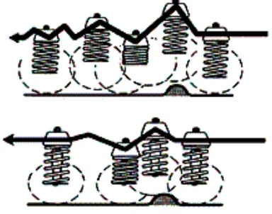
In a practical suspension system, the wheel is connected to the body through various links that permit an approximately vertical motion of the wheel relative to the body, controlled by the springs and dampers.
The main components of a suspension system are: 1 springs,
2 shock absorbers, 3 struts
4 tires
Figure 1 Spring movement
2.1.1 Springs
Springs are the flexible links that allow the frame and the body to ride
relatively undisturbed while the tires and suspension follow the bumps in the road. The springs support the weight of the vehicle, maintain ride height, and absorb road shock.
The major spring designs in use today are:
1. coil springs 2. leaf springs 3. torsion bar 4. air springs
2.1.1.1 Terminology used in the study of springs
The term bounce refers to the vertical (up and down) movement of the suspension system.
The downward travel of the tire and wheel that extends the spring and shock absorber is called rebound, or extension.
Spring rate is used to measure spring strength. It is the amount of weight that is required to compress the spring 1 inch.
Sprung weight is the weight supported by the springs. For example, the vehicle's body, transmission, frame, and motor would be sprung weight.
Unsprung weight is the weight that is not carried by springs, such as the tires, wheels, and brake assemblies.
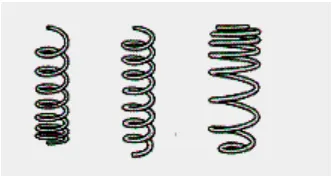
2.1.1.2 Coil springs
Coil springs are the most commonly used springs. The diameter and length of the wire determine the strength of a spring. Increasing the wire diameter will produce a stronger spring, while increasing its length will make it more flexible.
Some coil springs are made with a variable rate as shown in Figure 2. This variable rate is accomplished by either constructing this spring from materials having different thickness or by winding the spring so the coil will
progressively compress at a higher rate.
Figure 2 Coil spring types
2.1.1.3 Leaf springs
There are two major leaf spring design: multi-leaf and mono-leaf.
The multi-leaf spring as shown in Figure 3 is made of several steel plates of different lengths stacked together. During normal operation, the spring
compresses to absorb road shock. The leaf springs bend and slide on each other allowing suspension movement.
Figure 3 Leaf spring
In most cases leaf springs are used in pairs mounted longitudinally (front to back) but some of vehicle manufacturers are using a single transverse (side to side mounted leaf spring).
2.1.1.4 Torsion bar springs
mounted. During suspension movement, the torsion bar will twist, providing spring action.
2.1.1.5 Air springs
The air spring is another type of spring that is becoming more popular on
passenger cars, light trucks, and heavy trucks. The air spring as seen in Figure 4 is a rubber cylinder filled with compressed air. A piston attached to the lower control arm moves up and down with the lower control arm. This causes the compressed air to provide spring action. If the vehicle loads changes, a valve at the top of the airbag opens to add or release air from the air spring. An onboard compressor supplies air.
Figure 4 Air spring
2.1.2 Shock absorbers
Common types of shock absorbers illustrated in Figure 5 are:
1. oil filled 2. gas charged 3. reservoir
Figure 5 Types of shocks
2.1.2.1 Oil filled shock absorber
The most common type of shock absorber is oil filled. This type is used in car suspensions as well as bike suspensions. Many shock absorbers have adjustable spring rates and damping.
Some shocks have a rod extending into the centre of the shock that can be turned, allowing you to open or close more holes to adjust the damping. Some premium shocks have small one-way valves in the piston that open up holes when the piston is moving in one direction at different speeds, and close them when the piston is moving in the other direction.
2.1.2.2 Gas charged shock absorbers
There are shocks charged with gas, typically nitrogen. These shocks have an extra unattached piston in the bottom of the damper cylinder, with oil above the piston and high pressure gas below the piston. Typically, nitrogen at 30 to 300 psi is used because the oil would not combine (burn) with the nitrogen nearly as easily as it will with the oxygen in normal air.
2.1.2.3 Reservoir shock absorbers
The reservoir shocks have an extra oil reservoir attached with heat fins to help get rid of the heat.
2.1.3 Struts
Strut mounts are vehicle specific, and there are numerous designs in use today on both front and rear suspension systems.
The three most common designs are:
1. inner plate, illustrated in Figure 6; 2. centre sleeve;
3. spacer bushing.
2.1.4 Tires as springs
Tires are air springs that support the total weight of the vehicle. The air spring action of the tire is very important to the ride quality and safe handling of the vehicle. Tire size, construction, compound and inflation are very important to the ride quality of the vehicle.
There are three basic types of tires shown in Figure 7, namely:
1. radial ply, bias ply and bias belted; 2. bias ply;
3. bias belted.
Figure 7: Tire Types
2.1.4.1 Radial Tires
Radial ply tires have ply cords, which run across the centreline of the tread and around the tire.
The two sets of belts are at right angles. The belts are made of steel wire,
polyester or other substances. Today, radial tires come as original equipment on most passenger cars and light trucks.
2.1.4.2 Bias ply tires
2.1.4.3 Bias belted tyres
Bias belted tires are the same as bias ply, with the addition of layers of cords - or belts - circling the tire beneath the tread.
The air pressure determines the spring rate of the tire. An over inflated tire will have a higher spring rate and will produce excessive road shock. Over inflated tires will transmit road shock rather than reduce it. Over or under inflation also affects handling and tire wear.
2.1.5 Suspension types
Suspension systems can be broadly classified into two subgroups: dependent and independent. These terms refer to the ability of opposite wheels to move independently of each other.
2.1.5.1 Dependent suspension systems
A dependent suspension system normally has a simple beam axle that holds wheels parallel to each other and perpendicular to the axle. When the camber of one wheel changes, the camber of the opposite wheel changes in the same way.
Dependent systems may be differentiated by the system of linkages used to locate them, both longitudinally and transversely. Often both functions are combined in a set of linkages.
Examples of location linkages include:
Trailing arms
Panhard rod as seen in Figure 8 Watts linkage as seen in Figure 9 Inboard
WOB link
Figure 8 Panhard rod
Figure 9 Watts link
2.1.5.2 Independent suspension systems
An independent suspension allows wheels to rise and fall on their own without affecting the opposite wheel. In this case, the wheels are either not connected at all or are connected through universal joints with a swing axle
Independent front suspensions entirely replaced the rigid axel type after World War II and numerous independent rear suspensions came into use, first on European cars.
The main advantage of an independent suspension system is that is permitting the wheels to move independent to each other so that when one wheel hits a bump in the road, only that wheel is affected.
The variety of independent systems is greater and includes:
Swing axle;
MacPherson strut Wishbone;
Multi-link; Torsion bar;
Semi-trailing arm.
Figure 10 DeDion axle
However, a mixture of the two basic types is called a semi-dependent
suspension. In this case, a swing axle is used, but the wheels are also connected with a solid tube, most often a deDion axle.
New suspension technologies in development include a system from the Bose Corporation that uses computer-controlled motors to automatically adjust the suspension to changing road surfaces, keeping a vehicle level and in contact with the road even at high speed over bumpy roads, or in hard cornering.
2.1.6 Front and rear suspension design
The weight of a vehicle is unequally distributed between front and rear therefore the separate front and rear suspension mechanisms have to meet different requirements. Although few automobiles have a non-independent rear suspension, every modern car has an independent front suspension.
the wheels so that the vehicle travels in the intended direction and the tires remain essentially perpendicular to the road and do not wear abnormally.
There are several different front and rear suspensions system designs, including double A-arms and McPherson strut types (both of which have coil springs), torsion-bar springs and leaf springs.
The double A-arm system has normally completely independent suspension in the front or rear and are commonly used in sports and racing cars. It is a more compact system that lowers the vehicle hood resulting in grater visibility and better aerodynamics.
[image:28.595.270.382.372.513.2]The McPherson strut system is a coil spring wrapped around a shock absorber that acts as an upper control arm. It is less expensive than double A-arm system and is found in most modern front wheel-drive passenger vehicles.
Figure 11 MacPherson strut
2.2 Steering system
2.2.1 Manual steering systems
The manual steering system incorporates:
1. steering wheel and column;
2. a manual gear box and pitman arm or a rack and pinion assembly; 3. linkages, steering knuckles and ball joints;
4. wheel spindle assemblies.
There are several different manual steering gears in current use:
1. worm and sector type;
2. worm and tapered pin steering gear; 3. worm and roller steering gear
4. recirculating ball type where the balls acts as a rolling thread between the wormshaft and the ball nut;
5. rack and pinion type which is the choice of most vehicle manufacturers.
2.2.1.1 Worm and sector steering
The manual worm and sector assembly uses a steering shaft with a three-turn worm gear supported and straddled by ball bearing assemblies. In operation, a turn of the steering wheel causes the worm gear to rotate the sector and the pitman arm shaft and the movement is transmitted through the steering train to the wheel spindles.
2.2.1.2 Worm and tapered peg steering
worm gear, and that causes the tapered peg to follow the worm gear grooves. Movement of the peg moves the lever on the rocker shaft that in turn moves the rocker arm and the steering linkage.
Figure 12 Worm and peg steering
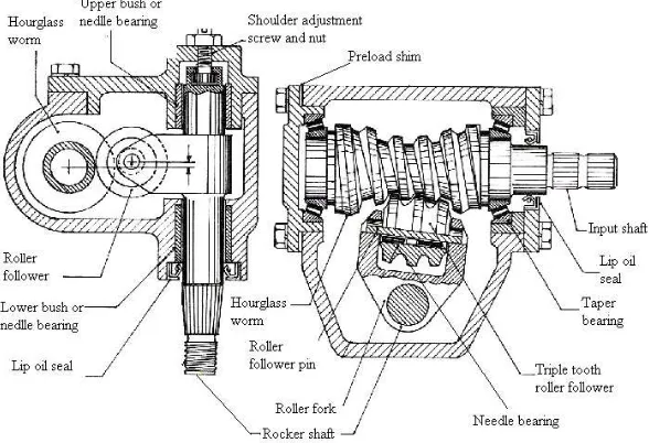
2.2.1.3 Worm and roller steering gear
Figure 13 Worm and roller type steering gear box
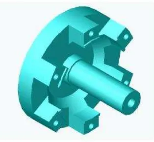
2.2.1.4 Manual recirculating ball and sector steering
Figure 14 Manual recirculating ball and sector steering
2.2.1.5 Manual rack and pinion steering
A typical rack and pinion steering gear assembly consists of a pinion shaft and bearing assembly, rack gear, gear housing, two tie rod assemblies, an adjuster assembly, dust boots and boot clamps, and grommet mountings and bolts. When the steering wheel is turned, this manual movement is relayed to the steering shaft and shaft joint, and then to the pinion shaft. Since the pinion teeth mesh with the teeth on the rack gear, the rotary motion is changed to transverse movement of the rack gear. The tie rods and tie rod ends then transmit this movement to the steering knuckles and wheels.
2.2.2 Power assisted steering system
Power steering makes a heavy car respond easily to the steering wheel, whether at highway speeds or inching into a narrow parking place, and it is normal equipment for large automobiles.
This system requires a power steering pump attached to the engine and driven by a belt, a pressure hose assembly, and a return line. Also, a control valve is incorporated somewhere in the hydraulic circuit. "Power steering" is really "power assisted steering." All systems are constructed so that the car can be steered manually when the engine is not running or if any failure occurs in the power source. Most power steering pumps contain a flow control valve, which limits fluid flow to the power cylinder, and a relief valve which limits pressure according to system demands.
Common types of power assisted steering systems are:
1. power rack and pinion; 2. power recirculating ball.
2.2.2.1 Power rack and pinion
Power rack and pinion steering assemblies are hydraulic/ mechanical unit with an integral piston and rack assembly. An diagram of a rack and pinion steering assembly is illustrated in Figure 16. An internal rotary valve directs power steering fluid flow and controls pressure to reduce steering effort. The rack and pinion is used to steer the car in the event of power steering failure, or if the engine (which drives the pump) stalls.
pressure on either side of the piston (which is attached to the rack) helps move the rack to reduce turning effort. The fluid in the other end of the power
cylinder is forced to the control valve and back to the pump reservoir. When the steering effort stops, the control valve is centred by the twisting force of the torsion bar, pressure is equalized on both sides of the piston, and the front wheels return to a straight ahead position.
Figure 16 Power rack and pinion steering system
2.2.2.2 Power recirculating ball
2.3 Geometry parameters involved in suspension and
steering
2.3.1 Wheel camber
2.3.1.1 Camber angle
Camber angle is regarded as the inclination of the wheel plane to the vertical (SAE J670e). Negative camber inclines the top of the tyre toward the centreline of the vehicle as seen in Figure 17 and positive camber inclines the top of the tyre away from the centreline.
Figure 17 Camber angle
A small amount of negative camber of up to 1.5 degrees it is recommended in order to induce camber thrust (Smith 2004). However, changes in camber should be kept at minimum during chassis roll in order to reduce the loss of camber thrust and the change in wheel track load distribution during cornering.
Chassis Upright
Front view
Top pivot
Bottom pivot Camber angle
2.3.1.2 Rate of camber change
The rate of camber change is the change of camber angle per unit vertical displacement of the wheel centre relative to the sprung mass (SAE J670e).
2.3.2 Wheel caster
2.3.2.1 Caster angle
Caster angle is the angle in side elevation between the steering axis and the vertical. It is considered positive when the steering axis is inclined rearward (in the upright direction) and negative when the steering axis is inclined forward (SAE J670e). Caster angle can be visualised on Figure 18.
Figure 18 Caster angle
Positive caster induces a self correcting force that provides straight line stability, but increases steering effort. Caster ranges from approximately 2 degrees in racing vehicles up to 7 degrees in sedans (Smith 2004).
Caster angle (positive)
Steering arm
Top pivot
Bottom pivot
Mechanical trail Forward
2.3.2.2 Rate of caster change
The rate of caster change is regarded as the change in caster angle per unit vertical displacement of the wheel centre relative to the sprung mass (SAE J670e).
2.3.3 Kingpin geometry
2.3.3.1 Kingpin inclination
The angle in front elevation between the steering axis and the vertical is regarded as kingpin inclination (SAE J670e). It is also known as steering axis inclination (SAI) and can be seen in Figure 19.
It is used to reduce the distance measured at the ground between steering axis and tyre’s centre of pressure in order to reduce the torque about the steering axis during forward motion. A right kingpin inclination will reduce the steering effort and will provide the driver with a good ‘road feel”
2.3.3.2 Kingpin offset
Kingpin offset measured at the ground is the horizontal distance in front elevation between the point where the steering axis intersects the ground and the centre of tyre contact (SAE J670e).
Figure 19 Kingpin inclination
The kingpin offset at the wheel centre is the horizontal distance in front elevation from the wheel centre to the steering axis (SAE J670e).
2.3.4 Wheel toe
2.3.4.1 Static toe angle
Static toe angle is measured in degrees and is the angle between a longitudinal axis of the vehicle and the line of intersection of the wheel plane and the road surface. The wheel is “toed-in” if the forward position of the wheel is turned toward a central longitudinal axis of the vehicle, and “towed-out” if turned away (SAE J670e).
2.3.4.2 Static toe
Static toe-in or toe-out of a pair of wheels is measured in millimetres and represents the difference in the transverse distance between the wheel planes taken at the extreme rear and front points of the tyre treads. When the distance
Chassis
Upright Tyre centre line
Bottom pivot Top pivot
Axle
Kingpin inclination
Scrub radius
at the rear is greater, the wheel is “toed-in” by this amount; and where smaller, the wheels are “toed-out” (SAE J670e) as illustrated in Figure 20.
Figure 20 Toe in/out
It is necessary to set the static toe such way to prevent the tyres to become toe-out during maximum bump and roll in order to prevent the toe-outboard tyre to steer the vehicle to the outside of the turn when cornering.
Toe-in produces a constant lateral force inward toward the vehicle centreline during forward motion that will enhance the straight line stability.
2.3.5 Ackermann steering
When a car goes round a corner, it turns around a point along the line of its rear axle, which means that the two front wheels will have to turn through slightly different angles so that they are also guiding the vehicle round this point, and not fighting the turn by scrubbing. This principle is illustrated in Figure 21.
Toe-in
[image:40.595.228.370.445.631.2]
Figure 21 Akerman principle
Ackerman geometry results when the steering is done behind the front axle and the steering arms point toward the centre of the rear axle as seen on Figure 22
Figure 22 Ackermann construction
Ackermann
θ
2.4. Suspension kinematic parameters
2.4.1. Instantaneous centre
The instantaneous centre of a suspension is the point through which an
individual wheel rotates and is also referred to as the “swing centre” or virtual half-shaft” (Smith 2000). It is also the point through which the respective tyre force acts on the sprung mass.
[image:41.595.115.535.423.639.2]The instantaneous centre of a four bar link independent suspension is located at the intersection of the lower and upper link extensions as seen in Figure 23. When analysing suspension kinematics, both left and right suspensions must be analysed together.
Figure 23 Instantaneous centre/ roll centre
Ground Instantaneous centre
Static roll centre Roll resistance arm
Wheel centre line Upright
Rollover moment arm C.G.
2.4.2. Roll centre
The point in the transverse vertical plane through any pair of wheel centres at which lateral forces may be applied to the sprung mass without producing suspension roll (SAE J670e).
2.4.2.1. Roll centre location
The roll centre is located at the intersection of the lines formed by the tyre contact patches and their respective instantaneous centres. In Figure 23 the tyre contact patches are assumed at the intersection of wheel centre line with the ground, while in reality these two points may not coincide. The location of the roll centre is usually different for front and rear suspension.
The vertical location or height of the roll centre determines the resulting two moment arms formed between the roll centre and both the C.G. and the ground plane. These two moment arms determine the vehicle’s sensitivity to lateral acceleration by producing rollover moments and jacking forces (Smith 2000).
2.4.2.2. Roll resistance arm
The roll resistance arm is the lever arm formed between the thread’s centre of pressure and the vehicle centre line. This moment arm creates a roll resisting torque when acted on by the reaction forces generated at the tyre contact patch by the spring and anti-roll bars (Smith 2000).
2.4.2.3. Rollover arm
of CG and vehicle’s centre line and finally the jacking forces acting on the arm formed by lateral displacement of the roll centre from the centre line during roll.
2.4.2.4 Jacking
The tyre reaction forces generated when the vehicle is accelerated during cornering are transmitted to the vehicle through the suspension links. In
Chapter 3
Analysis of the 2004 race car for design changes
The USQ 2004 racer car has been tested in the competition last year as well as on couple occasions this year. After minor modifications on the car to overcome the understeer effect and the uneven distribution of weight on the front and rear pair of wheels the test result this year were good in terms of handling and manoeuvrability. However, the overall performance of the car needs to be improved in order to make it competitive.
The overall car design was very robust with many components over designed and many afterthoughts chassis trusses and suspension brackets. Although very reliable it proved to add some unnecessary weight therefore reducing the
chances to meet the weight criteria.
3.1. Analysis of 2004 car steering system
3.1.1. Steering system geometry
3.1.2. Steering system mechanism
The steering mechanism used is shown in Figure 24 and consisted of a modified rack and pinion gearing in a custom made steering box. This mechanism was a good choice since the car is light and does not require power assistance, it is cheap, takes up a very small amount of space and is very responsive. However, the assembly had an amount of free play at the steering wheel above the design limit set by the competition rules.
Figure 24 2004 Steering box
3.2. Analysis of 2004 car suspension system
3.2.1. Suspension system type
The suspension system for 2004 racer car was four wheel independent
suspension with double wishbone, activated by push rod. The suspension layout was parallel arms with unequal lengths.
3.2.2. Suspension system components
3.2.2.1. Hub axle
Figure 25 2004 Front hub axle
3.2.2.2 Uprights
The uprights were fabricated from mild steel. The front upright has an
[image:46.595.244.401.72.217.2]incorporated 4.7 degrees of kingpin inclination. The design shown in Figure 26 allowed single shear top and bottom suspension mounting points, and that induced bending in the lower wishbone spherical rod end that is under the greatest load.
Figure 26 2004 Front and rear uprights
3.2.2.3 Control arms and suspension arm
and 2mm wall thickness. Adjustable spherical rod ends of different material and different dimensions were used. This variety of rod ends did not provided
consistency in the design that makes it difficult when tuning the car.
3.2.2.4 Springs and dampers
The motorbike spring/shock assembly used consists of coil spring mounted over oil filled adjustable shock absorber. The mounting position of the assembly was almost horizontally due to packaging constrains but was not according to the shocks specifications that require vertical mounting therefore reducing damper performance and causing oil liking. Therefore the position of the spring/shock should be carefully considered to comply with the shocks specifications and avoid such incidents.
3.2.2.5 Mounting points
Chapter 4
Design constrains
4.1 Design constrains set by the Formula SAE rules
4.1.1 Wheelbase and vehicle configuration
The car must have a wheelbase of at least 1525 mm (60 inches). The vehicle must have four wheels that are not in a straight line.
4.1.2 Vehicle track
The smaller track of the vehicle (front or rear) must be no less than 75% of the larger track.
4.1.3 Wheels
The wheels of the car must be 203.8 (8.0 inches) or more in diameter.
Any wheel mounting system that uses a single retaining nut must incorporate a device to retain the nut and the wheel in the event that the nut loosens.
4.1.4 Suspension
4.1.5 Steering
The steering system must affect at least two wheels and must have positive steering stops placed either on the uprights or on the rack. This is to prevent the steering linkages from locking up and the tyres from contacting suspension, body or frame members during track events.
Allowable steering free play is limited to 7 degrees total measured at the steering wheel. Rear wheel steering is permitted only if mechanical stops limit the turn angle of the rear wheels to ±3 degrees from straight ahead position. The steering wheel must be mechanically connected to the front wheels.
4.1.6 Steering wheel
The steering wheel must have a continuous perimeter that is near circular or near oval. The steering wheel must be attached to the column with a quick disconnect that can be operated by the driver in the normal driving position with gloves on (2005 Formula SAE rules)
The steering wheel must be attached to the column with a quick disconnect that can be operated by the driver in the normal driving position with gloves on (2005 Formula SAE rules)
4.1.7 Fasteners
All threaded fasteners utilised in the steering, breaking, safety harness and suspension must meet or exceed, SAE Grade5, Metric Grade M 8.8 and/or AN/MS specifications (2005 Formula SAE rules).
All spherical rod ends on the steering or suspension must be in double shear or captured by having a screw/bolt head or washer with an O.D. that is larger than spherical bearing housing I.D. Adjustable tie-rod ends must be constrained with a jam nut to prevent loosening (2005 Formula SAE rules).
4.2 Other design constrains
Chapter 5
Steering system design
5.1. Steering system requirements
A steering system must offer sufficient precision for the driver to actually sense what is happening at the front tyres contact patch as well as enough “feel” to sense the approach to cornering limit of the front tyres. It must be structurally stiff to avoid components deflections.
The steering must be fast enough so that the vehicle’s response to steering and to steering correction to happen almost instantaneous and it must also have some self returning action.
The feel, feedback and self returning action are function of the kingpin
inclination, scrub radius, castor angle and self aligning torque characteristics of the front tyre.
5.2. Design of the steering system geometry
Although modern cars do not use 100% Ackerman since it ignores important dynamic and compliant effects, the principle is sound for low speed
In consultation with the team, in our primary phase of the design we decided the wheelbase and the track width. However, at the beginning of the second semester a major decision was made to use for this year competition the previous year chassis.
Since the geometry used last year proved to work well, the decision was made to use for this year project same 100% Ackermann geometry.
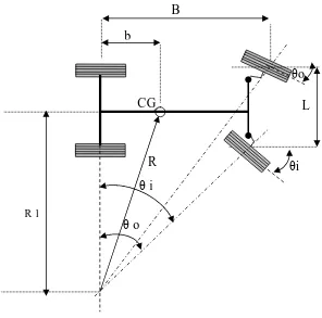
5.2.1 Ackermann condition
For the Ackermann analysis the Ackermann condition is used to determine the relationship between inner and outer wheel in a turn and the radius of turn.
General equation:
L B i o− θ =
θ tan
1 tan
1
Where: θo= turn angle of the wheel on the outside of the turn
θi= turn angle of the wheel on the inside of the turn
B= track width L= wheel base
[image:53.595.170.466.99.392.2]
Figure 27 Ackermann condition
From the general equation we can calculate the turn angle of the wheel on the outside of the turn for a given inside wheel angle as follows:
B=1800 mm L=1320 mm θi=30˚ ° = = + = + = 12 . 22 465 . 2 1800 1320 30 tan 1 tan 1 tan 1 o B L i o
θ
θ
θ
The minimum radius of turn R can be determined from the geometry:
θ i
θ o
m mm b R R m mm L i B R 86 . 3 3862 800 3778 1 7 . 3 3778 2 1320 30 tan 1800 2 tan 1 2 2 2
2 + = + = =
= = = + = + =
θ
Therefore the minimum radius of turn of the vehicle around its centre of gravity for a maximum inside wheel turn of 30 degrees is about 4 meters.
5.2.2 Selection of the steering parameters
The initial decision of zero degree kingpin inclination had to be reconsidered since the 56 mm of scrub radius resulted is large and will give an excessive feedback to the driver. Therefore 4 degree kingpin inclination is to be build in the front upright design that will result in an amount of scrub radius of 30mm calculated for last year wheel offset. Since this amount is still grater than 10% of the thread width (Heisler 1989), new wheels with less offset have been found therefore the resulting scrub radius is about 20 mm that is the amount we aimed for.
The amount of castor angle was set to 3.5 degree and is also build in the front uprights. However, castor angle can be adjusted by adjustment of the upper wishbone. This requires that one arm of the wishbone to be shortened while lengthening the other arm by screwing in or out the adjustable spherical rod ends. Another possible adjustment is to assemble the upright in an inclined position on the hub axle but this is not a handy method of adjustment.
5.3. Selection of the steering mechanism
-has a simple construction; - is cheap and readily available; - has a high mechanical efficiency; - has a reduced space requirement.
Since last year rack and pinion steering mechanism had an undesirable amount of free play the decision was made to modify one of the two steering
mechanisms sourced by the team members as donations for the project.
The rack and pinion steering box selected is from a Honda Civic 1983 and has a 5 teeth pinion gear and a pitch on the rack of 4.5mm.
The steering box assembly have been modified by Bruce Llewellyn, one of the team members. The rack has been shortened and the assembly was kept in the original steering box. The input shaft is not in a central position therefore the steering column will be connected to the input shaft through a universal joint.
Figure 28 Modified steering box assembly
5.4. Position of the steering mechanism
5.4.1 Position relative to the front axle
Figure 29 Top view diagram of steering system geometry
5.4.2 Position in a vertical plane
In a vertical plane, two placement possibilities were investigated. To place the steering box at the bottom of the chassis just above the bottom chassis rails or to place it above the actual position such as the steering column will be
horizontal. The first possibility would cause trouble in getting into the car when the driver’s feet must pass first over the steering mechanism. Even worse
getting out of the car when the hell of the foot will be caught by the
mechanism. Therefore, this option is inconvenient leaving the only possibility to place the steering box above the actual position.
For this location the steering assembly is at a higher position than the steering arm even though the steering arm is attached to the upright above the centre of the wheel. Therefore, the steering linkages had to be redesigned. The solution was to use a rocker arm but this will result in a reversed movement of the tie-rod relative to the rack as seen in Figure 30.
Tie rod Front axle
centre line Upright
50 mm
Steering box
Rack housing
Figure 30 Front view diagram of steering system geometry
The problem can be overcome by reversing the position of the rack relative to the pinion as seen in Figure 31.
Figure 31 Position of the pinion relative to the rack
Another problem encountered was that the pivot points of the rocker arm will follow a circular path producing a displacement of the rack and pinion assembly therefore the assembly has to have a small amount of rotational freedom. The solution for this problem is to have a rather floating steering box attached to the chassis upper rail seen in Figure 32 or in Appendix E.
Pinion Rack
Rocker arm
Left Upright Tie rod
Rack housing
Rocker arm
Wheel centre Steering arm
Figure 32 Mounting of the steering box
After the suspension components are assembled on the chassis and the steering mechanism in place, the distance between lower rocker arm pivot point and steering arm mounting point can be measured, hence the length of the tie rod can be determined. The tie rod will have left and right threaded spherical rod ends for adjustment of the link length as a method of adjustment of the bump steer.
5.5 Bump steer geometry
In the design of the steering geometry, the bump steer and roll steer effect should be taken into account. Bump steer results from the combination of wheel toe in or toe out with wheel vertical travel while the roll steer is produced by the combination of toe in/out and body roll. The suspension and steering links should be placed such way to minimise the distortion of the steering geometry with suspension movement. For this reason, to minimise the bump steer, the steering tie rod should be parallel with the upper wishbone and to minimise roll steer the upper wishbone inboard pivot points should be in the same vertical plane with tie rod inboard pivot point.
Upper chassis rail
5.6 Steering movement ratio
The rack and pinion mechanism is designed to transfer the circular input motion of the pinion into linear output movement of the rack.
It was measured that for a full travel of the rack of 137 mm the pinion has to be rotated 31/8 turns
Therefore for one turn, the rack travel will be:
mm xo 43.84
125 . 3
137 = =
Considering the pinion to make one revolution then the input steering movement is:
R xi =2
π
Where, R = 155 mm is the radius of the steering wheel.
And the output rack movement is:
7 97 . 6 2 84 . 43 84 . 43
2 = ⇒ = = =
=
π
π
r rxo
Then, the movement ratio can be calculated as input movement over output:
22 7 155 2
2 = =
= = r R x x MR o i
π
π
We needed to know the movement ratio in order to determine the output load transmitted to the tie rods for a given input load.
For an effort of 20 N applied by each hand on the steering wheel and considering no friction, the output load will be:
N x
x xMR F
Fo = i =2 20 22=880
Therefore the load transmitted to the tie rods is 880 N.
5.7 Quick release mechanism
As a requirement of the design for the competition the steering wheel must be present with a quick release mechanism. Following discussion with the team it was decided to make use of the last year quick release mechanism. The
Chapter 6
Suspension system design
6.1 Design approach
Choosing suspension geometries and components involves a wide range of choices and compromises. An analysis of the tyre, chassis and road interaction is required to decide the trade-offs that will result in an optimum configuration for the type of vehicle and the nature of the race track for which the vehicle has to perform.
The basic steps in designing a vehicle’s suspension are:
- selection of the suspension type to be employed; - selection of the wheels;
- establish the vehicle’s dimensions – wheel base and track width(s); - set up suspension parameters;
- model the suspension geometry; - design components.
6.2 Suspension type and geometry selection
The starting point in designing the geometry of suspension system was to first select the type and the geometry of the suspension. Double wishbone
Two options were investigated for the geometry of the suspension: parallel arms with unequal lengths layout used for last year design and unparallel arms with unequal lengths. Although previous year design was a good choice, for this year project the second option was selected. The unparallel arms will result in a lower roll centre that will produce a bigger roll moment arm, hence more roll for the sprung mass and less jacking force.
6.3 Wheel selection
Then a decision had to be made about the wheels to be used. One of the team members investigated the availability and cost of wheels and the team decision was that a 13 inches wheel with at least 20 mm offset is to be used.
6.4 Wheelbase, track width and pivot points location
The wheelbase is the distance between the front and rear axles and has to be determined prior to chassis design. The advantages of a relatively long wheelbase are increased straight line stability, reduced longitudinal load transfer and more room to pack components in while the advantages of a relatively short wheelbase is reduced overall weight and increased manoeuvrability (Smith 1978).
The track width is the distance between a pair of wheels centre lines and is determined by the lengths of the links. The advantages of wide track width are reduced lateral load transfer for a given amount of centrifugal acceleration and less camber change. The increase in the frontal area will represent a
disadvantage only for high speeds where the aerodynamics plays an important role.
expenses of cornering power and manoeuvrability while a race car with short wheelbase and wide tracks will be lass stable, will develop more cornering power and be more manoeuvrable. In addition, a wider track width at the front than at the rear will provide more stability in turning the car into corners decreasing the tendency of the car to trip over itself on corner entry and more resistance to diagonal load transfer.
Giving all the above considerations, the wheelbase agreed on was 1650 mm, which is slightly shorter than last year’s design and a track width of 1370mm at the front and 1280mm at the rear.
The pivot points location was decided initially on the drawings of the chassis provided by Tony O’Neal who is designing the chassis. The chassis has been manufactured by the beginning of second semester but it was thought that due to time and cost constrains a decision have to be made in order to ensure the completion of the project. Therefore, the team decided to use for this year application the previous year chassis because had already components that can be used like fuel tank, fire wall, brake pedals, etc which do not require time to manufacture and assemble.
This had been a critical decision in terms of suspension design that had to be entirely reconsidered. The wheelbase is now 1800mm while but the track width is not affected and so the link lengths can be calculated.
6.5 Geometry parameters selection
Since camber is easily adjustable by the lengths of the control arms, an initial three degrees static negative camber angle is to be trial on the test track. The goal is to achieve the minimum change in camber over the range of suspension travel.
The change in camber with 10 mm bump/drop and 1 and 3 degrees of roll on the final suspension geometry has been modelled in AutoCAD as can be seen in Appendix F.
Another important suspension parameter is the roll centre. Both roll centre and camber angle have been defined in 2.4.2. Roll centre. A position of the roll centre has been also modelled with AutoCAD software and the result as seen in Appendix F is 70 mm below the ground.
Camber change Track width change
10 mm bump 0.48 deg. 1.35 mm
1 deg. roll 0.42 deg 2.02 mm
3 deg. roll 2.25 deg 15.25 mm
6.6 Suspension components design
6.6.1 Hub axle
Since this year identical break components have been sourced, the decision was to use the same hub axle because it has been designed to accommodate those particular brake components. However, the hub was too heavy and a Finite Element Analysis showed that the component was over designed.
Appendix B. The detail drawing of the component showing the dimensions to be modified is attached in Appendix D.
6.6.2 Uprights
The 2004 uprights design have been analysed and thorough consideration for the competition rules that allows for spherical rod ends in single shear captured by an appropriate screw/bolt had been given. However, the judges did criticise this practice and strongly encouraged for the double shear design of the
spherical rod ends pivot points.
Considering this and the fact that the modified hub axle shaft diameter is smaller the decision was to entirely redesign the uprights.
6.6.2.1 Method of fabrication
In order to decide the method of fabrication of the components, three options were investigated.
Option 1 – Machine the component from one piece of material.
This option can result in a compact design with intricate shape if necessary and allows the use of a wide range of materials like aluminium alloys which will result in a much lighter component.
However, later modifications of the design will not be possible therefore the design must be from the beginning very precise. Apart from that it requires skilled operator and together with the cost of the material will result in a relatively high total cost of the component.
Option 2- Fabricate the component by casting
special facilities for casting process. Although the initial cost of the dies is high, it is divided by the number of components produced so, for a thousand units production the cost per unit will be relatively low. Once again, the design dimensions must be accurate.
Option 3 – Fabricate the component by welding parts together
The advantage of this method is that the materials are inexpensive and available in the workshop shelves and does not require skilled labour to fabricate the component. It is also possible to modify the design at a later stage if necessary. This option will result in a relatively heavier component compared with option one but with a lower total cost.
The decision was to compromise on weight of the component to gain in cost and in the advantage of easily modify and adjust the upright design in the case of other components design changes. Hence, the selected method for fabrication of the uprights was by welding.
6.6.2.2 Material selection
The criteria used in the material selection for manufacture of the uprights was:
1. the material have to be easy to be machined, cut and welded; 2. have to be relatively light for its strength;
3. have to be relatively inexpensive and available.
After discussion with the USQ workshop it was found that only mild steel fitted all the criteria and that a wide range of dimensions and cross sections are
6.6.2.3 Design concepts
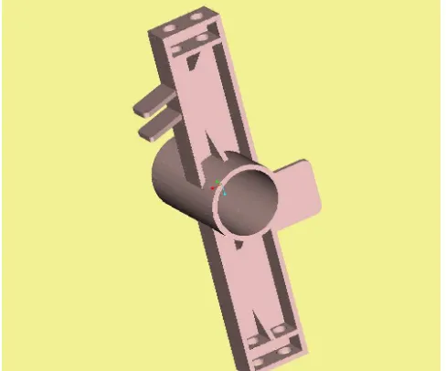
Design concept 1
[image:67.595.205.449.379.582.2]The first general design concept of the uprights consisted of a circular section with machined inside diameters to suit the wheel bearings. Two parts of “C” channel with appropriate manufactured end configuration for the wishbones assembly are to be welded on top and bottom of the circular part. The steering arm, and brake calliper mounting bracket is then welded on the upright. This concept is illustrated in Figure 33. The front upright provides a zero kingpin inclination and an adjustable zero or three degrees caster.
Figure 33 Upright design concept 1
Design concept 2
The second design concept uses the same circular section for the bearings housing but has a RHS square section welded on the top and bottom. A
different end configuration for the wishbone pivot points is to be welded on the other ends of this section. This configuration allows for a kingpin inclination and caster to be build in. This design is illustrated in Figure 34.
Final design
Both designs have a manufacture medium to low degree of difficulty since they uses simple parts. The cost of fabrication is expected to be near the same. However using an open section like the “C” channel used in the first design has the disadvantage of less torsional stiffness than a closed section. The addition of ribs to reinforce the structure will add more parts into the component hence increasing the weight and complexity without achieving same degree of
stiffness expected from a closed section. Moreover the first design does not allow for later modification of the wishbones pivot points locations, while for the second design the brackets can be easily removed and welded back in a different position. This provision for easy adjustment of the pivot points it eliminates the necessity to remanufacture the whole component in the eventuality of later changes in geometry of the suspension.
Figure 34 2005 Front and rear final design
6.6.3 Control arms (wishbones) and suspension arm
6.6.3.1 Material selection
In selecting the material for the wishbones same criteria had to be considered as for the uprights material selection.
ERW circular steel tube appeared to be a good choice and after discussion with the USQ workshop staff it was found that is low-priced and the common sizes can be delivered in just a week time therefore, the material matched up the selection criteria.
Hence, the material selected was ERW circular steel tube with an OD of 19 mm and thickness of 1.6 mm that will allow an overall links weight reduction of about 1.5 Kg comparing with last year design.
However, for the rod ends we have been offered sponsorship from Linear Bearings Pty Ltd for industrial grade and imperial units equivalent with the metric ones initially selected. Although some minor modifications had to be made to the uprights pivot points due to small differences in dimensions, the rod ends offered were suitable for our application in terms of strength and cost. Therefore the offer has been gratefully accepted.
The spherical rod ends and spherical bearings specifications are as follows:
Type Bore and thread
UNF
Head diameter (inch)
Thread length (inch)
INDUSTRIAL ROD ENDS AM6GP
(steel on steel)
3/8 x 3/8 0.406 1.250
AML6GP (steel on steel)
3/8 x 3/8 0.406 1.250
STAINLESS STEEL SPHERICAL PLAIN BEARINGS
Type Bore diameter Outside diameter Ball width
ABWT8 1/2 1.000 .625
6.6.3.2 Design concept
Once the track width was known, the lengths between pivot points could be calculated. Thus, taking in consideration distances between pivot points on the chassis and the dimensions of the rod ends as well as the geometric
configuration of each component, the exact lengths of the wishbones was establish.
Front suspension
Figure 35 Upper wishbone - front suspension
The lower wishbone consists also of two links and as I mention before has spherical bearings at the outboard ends. For this spherical bearing a casing had to be designed. The links are welded on to this casing therefore the component is rigid with no possibility of adjustment. On the casing are also welded
brackets for the suspension arm pivot point. The design is illustrated in Figure 36.
Figure 36 Lower wishbone - front suspension
Rear suspension
The rear suspension, have to accommodate a toe control rod therefore provision for the outboard pivot point was included in the rear upright design. For this reason the design of the upper rear wishbone is different than for the upper front as can be seen in Figure 37.
Figure 37 Upper wishbone - rear suspension
Suspension arm
The suspension arm is a single rod with two spherical rod ends fitted in a welded boss.
At this stage, the position of the shock/spring assembly and rocker arm is known with approximation, hence the exact dimension of this component can’t be yet calculated. Once the spring/shock assembly is mounted on the chassis and all other suspension components are in place, an exact measure between the rocker arm pivot point and the outboard pivot point will establish the length of this component.
6.6.4 Mounting points
A decision had to be made if the brackets on the last year chassis are to be kept or removed.
It was suggested that for the lower mounting points to make use of the chassis bottom rail as seen in Figure 38. This idea has been considered in the design since it has the benefit of reducing the amount of brackets.
For the upper mounting points the brackets are to be welded in a vertical plane to allow for more movement freedom of the control arms. The design will also allow for two mounting positions as seen in Figure 38 for adjustment of the inclination of upper wishbone relative to the lower one.
Figure 38 Mounting points
6.6.5 Springs, shock absorbers and anti-roll bars
6.6.5.1 Position of the spring and shock absorbers
It is a common practice to have the springs mounted over the shocks because it minimises space requirements. For the purpose of this project, this will be regarded as spring/shock assembly.
The chassis roll is restricted by the compression of the springs hence the physical placement of the suspension springs determines how much roll resistance they will offer.
Chassis rail
Options for the location of spring/shock assembly
For selection of the spring/shock assembly location there are multiple options depending on the application and the packaging constrains. However there are two main possibilities: to mount the spring/shock assembly inboard (within the chassis) or outboard (outside the chassis).
For the inboard mounting, the assembly is at some distance for the wheel centre line and that requires a link and a rocker arm. The link, called suspension arm, can be either a pull rod if will extend the spring while the wheel goes over a bump or the opposite, a push rod if the spring will be compressed.
Another possibility is outboard mounting when the upper spring/shock
assembly pivot is attached to the main chassis structure and the lower pivot is attached to either the upright or the lower wishbone.
Position of the spring/shock assembly
Outboard mounting for front spring/shock assembly is not a viable option since between the upper and lower wishbones is going to be the steering tie rod. Hence, the only choice was inboard mounting of the assembly that will be actuated by a push rod.
After a thorough examination of the last year chassis and all the components assembled on it, and discussion with the team, the conclusion drown was that at the front between the upper and lower chassis rails is the most appropriate location for the spring/shock assembly as seen in Figure 39. While the location will not permit for a vertical position of the shocks, it will allow for more room inside the front chassis to better position of the steering and breaking
Figure 39 Spring/shock position
At the rear again an outboard mounting position of the spring/shock assembly is not an option since the space it is been taken by the rear axle CV joints. Hence the rear spring/shock assembly will be also attached between the upper and lower chassis rails.
6.6.5.2 Spring rates and wheel rates
The relationship between wheel rate and spring rate is a function of motion ratio between wheel travel and spring axis travel and the formula is
(Smith1978):
2 MR
SR WR=
For the given wheel travel of 50.8mm (2 inches) we can calculate the spring travel for a given motion ratio.
Upper chassis rail Front hoop
Rocker arm
Lower chassis rail Spring/shock
assembly
MR WT ST ST WT
MR= ⇒ =
MR WT(mm) ST(mm) WT(mm) ST(mm)
1.3 25.4 19.53846 50.8 39.07692
1.4 25.4 18.14286 50.8 36.28571
1.5 25.4 16.93333 50.8 33.86667
1.6 25.4 15.875 50.8 31.75