New Design Methodologies for Printed Circuit
Axial Field Brushless DC Motors
by
Daniele Marco Gambetta, MPhil, B.Sc (Hons)
Dissertation Submitted in Fulfillment
of the Requirements for the Degree of
Doctor of Philosophy
at the
The University of Southern Queensland
Faculty of Engineering & Surveying
Copyright by Daniele Gambetta
iii
Abstract
A number of factors are contributing to the increased practical importance of printed circuit axial flux brushless direct current (BLDC) machines. The main ones are the availability of low cost power electronic devices and digital controllers as well as cost effective high strength permanent magnets. Advancement of multi-layer printed circuit technology is also an important factor. Existing printed circuit board motors, found in applications such as computer disk drives and portable audio-visual equipment, are typically rated at a few watts per thousand revolutions per minute (krpm). The focus of this thesis project has been on printed circuit motors with ratings of a few tens of watts per krpm.
iv
BLDC motors that operate in sensorless mode has advantages such as lower cost, better reliability and space saving. A new generalised version of the previously reported equal
inductance method has been developed which allows sensorless commutation of printed circuit
BLDC motors down to zero speed and start-up with practically no back rotation.
Computer efficient numerical models have been developed to predict phase inductances and stator eddy-current loss. Sufficiently accurate phase inductance predictions make possible theoretical assessment of performance of motors under sensorless commutation control that is based on the equal inductance method. The proposed method of calculation of eddy current loss allows designers to determine the track width beyond which eddy current loss becomes excessive.
v
Certification of Thesis
I certify that the ideas, experimental work, results, analyses, software and conclusions reported in this dissertation are entirely my effort, except where otherwise acknowledged. I also certify that the work is original and has not been previously submitted for any other award, expect where otherwise acknowledged.
____________________________ _________________________
Signature of Candidate Date
ENDORSEMENT
____________________________ _________________________
Signature of Supervisors Date
vi
Acknowledgments
I would sincerely like to thank and acknowledge the following people for their assistance, guidance and support throughout the duration of this thesis project.
First of all I would like to thank my supervisor Dr Tony Ahfock. Throughout the course of the research he maintained a constant interest and provided invaluable assistance and guidance in the development of this work. Much of the work developed and presented herein was discussed with and reviewed by Dr Tony Ahfock. I wish to acknowledge the significant contributions he made by in the preparation and production of this thesis.
vii
I wish to thank the Faculty of Engineering and Surveying and the Office of Research and Higher Degrees for their support and assistance. My thanks also extends to all those at the University who made this such a pleasant experience.
viii
Contents
ABSTRACT ... III
CERTIFICATION OF THESIS ...V
ACKNOWLEDGMENTS ... VI
CONTENTS ... VIII
LIST OF TABLES ... XIV
LIST OF FIGURES ... XVI
LIST OF SYMBOLS ... XXII
PUBLICATIONS ... XXX
CHAPTER 1 INTRODUCTION ... 1
ix
1.2 BACKGROUND INFORMATION ON BRUSHLESS DCMOTORS ... 3
1.3 BACKGROUND INFORMATION ON PRINTED CIRCUIT BLDCMOTORS ... 7
1.4 SENSORLESS OPERATION ... 14
1.5 THESIS PROJECT OBJECTIVES ... 15
1.6 OUTLINE OF DISSERTATION ... 16
1.7 MAIN OUTCOMES OF THE THESIS PROJECT ... 18
CHAPTER 2 LITERATURE REVIEW AND METHODOLOGY ... 21
2.1 LITERATURE REVIEW ... 21
2.1.1 Printed Circuit Motors ... 22
2.1.2 Sensorless Operation ... 26
2.1.3 Measurement of Inductances and Inductive Saliency ... 28
2.1.4 Prediction of Inductances and Inductive Saliency ... 30
2.2 METHODOLOGY ... 32
2.2.1 Design options and procedure ... 32
2.2.2 Modification and adaptation of the equal inductance method ... 40
CHAPTER 3 PRINTED CIRCUIT STATORS FOR BRUSHLESS PERMANENT MAGNET MOTORS ... 43
3.1 INTRODUCTION ... 43
3.2 ANALYSIS OF COIL GEOMETRIES... 45
3.2.1 Purely Parallel Coils ... 47
3.2.2 Purely Radial Coils ... 50
x
3.3 PREDICTING COIL EMF’S ... 54
3.3.1 Approximate Analytical Modelling ... 56
3.3.2 Predicting Coil EMFs Numerically ... 59
3.4 EXPERIMENTAL VERIFICATIONS ... 66
3.4.1 EMF Waveforms ... 66
3.4.2 Thermal Considerations ... 69
3.4.3 Resistance Optimization ... 74
3.4.4 Parallel Track Sections versus Mixed Track Sections ... 78
3.4.5 Single Layer Machines ... 79
3.4.6 Number of Poles ... 81
3.4.7 Ratio of Inner Radius to Outer Radius ... 81
3.5 DESIGN OPTIMIZATION ... 82
3.6 CONCLUSIONS... 87
CHAPTER 4 SENSORLESS COMMUTATION TECHNIQUE FOR BRUSHLESS DC MOTORS ... 88
4.1 INTRODUCTION ... 88
4.2 RELATIONSHIP BETWEEN EQUAL INDUCTANCE POSITIONS AND COMMUTATION POSITIONS ... 89
4.3 DETECTION OF EQUAL INDUCTANCE POSITIONS ... 94
4.4 INITIAL POSITION DETECTION AND START-UP ...102
4.5 TEST RESULTS ...106
xi
4.7 CONCLUSION ...111
CHAPTER 5 SENSORLESS COMMUTATION OF PRINTED CIRCUIT BRUSHLESS DC MOTORS ...114
5.1 INTRODUCTION ...114
5.2 CHARACTERISTICS OF TEST MOTORS ...115
5.3 DETERMINATION OF COMMUTATION POSITIONS ...118
5.4 INITIAL POSITION DETECTION ...129
5.5 PRACTICAL INVESTIGATIONS AND TEST RESULTS ...134
5.6 PRACTICAL CONSIDERATIONS ...141
5.6.1 Motor Stiction ...141
5.6.2 Power Semiconductor Voltage Drops Compensation ...142
5.6.3 Computation Burden and Speed Range ...145
5.7 CONCLUSIONS...146
CHAPTER 6 STATOR EDDY CURRENT LOSSES IN PRINTED CIRCUIT BRUSHLESS MOTORS ...148
6.1 INTRODUCTION ...148
6.2 CHARACTERISTICS OF TEST MOTORS ...149
6.3 EDDY CURRENT MODELLING ...152
6.3.1 Formulation of the Eddy Current Problem ...152
6.3.2 Determination of Magnetic Flux Density Distribution ...154
6.3.3 Induced Current Evaluation ...156
xii
6.3.5 Determination of Eddy Current Loss Distribution ...161
6.4 THEORETICAL PREDICTIONS ...163
6.4.1 Effect of Track Width and Number of Turns ...163
6.4.2 Consideration on the Relation between Eddy Current Ripple and Axial Flux Distribution ...168
6.4.3 Level of Discretisation ...173
6.4.4 Effect of Substrate Position ...174
6.4.5 Eddy Current Paths ...175
6.4.6 Co-existence of Eddy and Load Currents ...178
6.5 EXPERIMENTAL VALIDATION ...180
6.6 COMPARISON BETWEEN I2R AND EDDY CURRENT LOSS ...184
6.7 CONCLUSION ...185
CHAPTER 7 PREDICTION OF INDUCTANCES OF PRINTED CIRCUIT MOTORS 186 7.1 INTRODUCTION ...186
7.2 BASIC PRINCIPLES ...187
7.3 PREDICTION OF DIRECT AXIS INDUCTANCES ...190
7.3.1 The Coupled Network Model ...190
7.3.2 Branch Reluctance and Loop Resistances ...197
7.3.3 Boundary Conditions ...200
7.3.4 Magnetic Circuit Loop Analysis ...202
7.4 PREDICTION OF QUADRATURE INDUCTANCES ...206
xiii
7.6 EXPERIMENTAL VALIDATION ...216
7.7 CONCLUDING REMARKS ...221
CHAPTER 8 CONCLUSIONS ...222
8.1 THESIS PROJECT ACHIEVEMENTS ...222
8.2 FUTURE WORK ...227
REFERENCES ...229
APPENDIX A FIRST ORDER MAGNETIC MODEL ...238
A.1 THE MODEL ...238
A.2 RELUCTANCE COMPUTATION ...241
A.3 FLUX DENSITY COMPUTATION ...243
APPENDIX B FIRST ORDER STATOR EDDY CURRENT MODEL ...244
B.1 THE MODEL ...244
APPENDIX C FIRST ORDER SELF INDUCTANCE MODEL ...247
C.1 THE MODEL ...247
APPENDIX D PHOTO GALLERY ...250
xiv
List of Tables
TABLE 2.1:MAIN PRINTED CIRCUIT MOTOR DESIGN PARAMETERS ... 36
TABLE 3.1:MOTOR TEST DATA ... 68
TABLE 3.2:PRINTED CIRCUIT MOTOR DESIGN EXAMPLE ... 86
TABLE 4.1:EQUAL INDUCTANCE POSITIONS AND COMMUTATION INTERVALS ... 92
TABLE 5.1:COMMUTATION INTERVALS ...119
TABLE 5.2:VALUE OF SENSED VOLTAGE DIFFERENCES AT FIRST COMMUTATION POSITIONS .132 TABLE 5.3:COMMUTATION TIME MULTIPLIER Γ ...140
TABLE 6.1:TEST MOTOR DETAILS ...151
TABLE 6.2:FORCE MEASUREMENTS WIDTH DIFFERENT TRACK WIDTHS ...182
TABLE 6.3:FORCE MEASUREMENTS ...183
TABLE 7.1:MEASURED AND PREDICTED SELF INDUCTANCES ...217
TABLE 7.2:MEASURED AND PREDICTED MUTUAL INDUCTANCES ...218
xv
xvi
List of Figures
FIGURE 1.1:BLDCROTORS WITH SURFACE MAGNETS (SOURCE: REFERENCE [1]) ... 3
FIGURE 1.2:BLDCROTORS WITH INTERNAL MAGNETS (SOURCE: REFERENCE [1]) ... 4
FIGURE 1.3:INVERTER FED BLDCSTATOR WINDINGS ... 5
FIGURE 1.4:IDEALISED CURRENTS SUPPLIED BY INVERTER ... 6
FIGURE 1.5:WAVE WINDING (SOURCE: REFERENCE [4]) ... 8
FIGURE 1.6:RHOMBOIDAL WINDING (EXAMPLE OF A SPIRALLY SHAPED COIL)... 9
FIGURE 1.7:COILS WITH PARALLEL ACTIVE SECTIONS ... 10
FIGURE 1.8:COILS WITH RADIAL ACTIVE SECTIONS ... 11
FIGURE 1.9:DISTRIBUTION OF COIL ON ONE PRINTED CIRCUIT LAYER ... 12
FIGURE 1.10:EXPLODED VIEW OF A PRINTED CIRCUIT AXIAL FIELD BRUSHLESS MOTOR ... 12
FIGURE 2.1:GENERALISED PRINTED CIRCUIT MOTOR DESIGN OPTIMISATION FLOW-CHART .. 39
FIGURE 3.1:(A)TOP LAYER SPIRAL (B)BOTTOM LAYER SPIRAL ... 46
xvii
FIGURE 3.2(B):EXAMPLE OF PRINTED COIL WITH PARALLEL TRACKS ... 48
FIGURE 3.3(A):RADIAL TRACKS ... 51
FIGURE 3.3(B):EXAMPLE OF PRINTED COIL WITH RADIAL TRACKS ... 51
FIGURE 3.4:MIXED TRACK ... 53
FIGURE 3.5:SECTION OF SUBSTRATE ... 54
FIGURE 3.6:EXPLODED VIEW OF ONE OF SIX TEST MOTORS ... 56
FIGURE 3.7:TRACK SEGMENT IN A CELL ... 60
FIGURE 3.8:FEMLAB®MODEL OF THE ROTOR ... 61
FIGURE 3.9:B-HLOOPS OF ROTOR MATERIAL ... 63
FIGURE 3.10:OUTPUT FROM FINITE ELEMENT ANALYSIS ... 64
FIGURE 3.11:“B”POINT “MAX SHIFT” IN DIRECTION OUTER RADIUS ... 65
FIGURE 3.12:“B”POINT IN INTERMEDIATE POSITION BETWEEN OUTER AND INNER RADIUS ... 65
FIGURE 3.13:PHASE EMFWAVEFORMS ... 67
FIGURE 3.14:THE 1-DTHERMAL MODEL ... 70
FIGURE 3.15:PHASE A(TOP PHASE)TEMPERATURE RISE ON TIME ... 73
FIGURE 3.16:PHASES VOLTAGE DROP ... 74
FIGURE 3.17: A)LAYERS STRUCTURE; B)RESISTIVE STRUCTURE ... 77
FIGURE 3.18:TORQUE CAPABILITY VERSUS NUMBER OF POLES ... 78
FIGURE 3.19:SINGLE LAYER MACHINE PHASE EMFWAVEFORM AT 1000 R/MIN ... 80
FIGURE 3.20:SELF-INDUCTANCE LBBSINGLE LAYER STATOR ... 80
FIGURE 3.21:TORQUE CAPABILITY VERSUS MAGNET THICKNESS ... 85
FIGURE 4.1:MEASURED SELF-INDUCTANCES ... 91
xviii
FIGURE 4.3:EQUIVALENT CIRCUITS FOR INVERTER STATES A+B- AND B+A- ... 96
FIGURE 4.4:VOLTAGE SAMPLING INSTANTS ... 97
FIGURE 4.5:MEASURED VOLTAGE DIFFERENCES ...102
FIGURE 4.6:COMMUTATION ALGORITHM BASED ON THE EQUAL INDUCTANCE METHOD ...105
FIGURE 4.7(A):ESTIMATED ROTOR POSITION ...106
FIGURE 4.7(B):POSITION ERROR ...107
FIGURE 4.8:BLDCCOMMUTATION USING THE EQUAL INDUCTANCE METHOD ...108
FIGURE 4.9:BLDCCOMMUTATION USING THE EQUAL INDUCTANCE METHOD ...108
FIGURE 4.10:FIRST COMMUTATION EVENT ...109
FIGURE 5.1:SELF-INDUCTANCES OF TEST MOTOR 2 ...116
FIGURE 5.2:MUTUAL-INDUCTANCES OF TEST MOTOR 2 ...117
FIGURE 5.3:INVERTER BRIDGE AND STATOR WINDING ...119
FIGURE 5.4:EQUIVALENT CIRCUITS FOR INVERTER STATES A+B- AND B+A- ...121
FIGURE 5.5:VOLTAGE SAMPLING INSTANTS ...123
FIGURE 5.6:RELATIONSHIP BETWEEN VOLTAGE ZERO CROSSINGS AND COMMUTATION POSITIONS ...125
FIGURE 5.7:VOLTAGE DIFFERENCE WAVEFORMS ...130
FIGURE 5.8:EXPERIMENTAL VERIFICATION OF EQUATIONS 12,14 AND 16 ...134
FIGURE 5.9(A):ESTIMATED ROTOR POSITION ...135
FIGURE 5.9(B):POSITION ERROR ...136
FIGURE 5.10:COMMUTATION CONTROL ALGORITHM ...138
FIGURE 5.11:COMMUTATION UNDER LOAD AT 750 RPM, A)MOTOR 1, B)MOTOR 2 ...139
xix
FIGURE 5.13:MEASUREMENTS ON MOTOR 1 ...144
FIGURE 6.1:COIL SHAPE USED FOR THE MACHINE’S STATOR...150
FIGURE 6.2:FEMLAB®MODEL OF THE ROTOR ...154
FIGURE 6.3:SUBDIVISION OF THE PRINTED COPPER TRACKS ...158
FIGURE 6.4:EXAMPLES OF LOOPS AND THE ADOPTED LOOP NUMBERING SYSTEM ...162
FIGURE 6.5:CALCULATED EDDY CURRENT LOSS FOR DIFFERENT TRACK WIDTHS ...164
FIGURE 6.6:PER TURN LOSS WITH 3.7 MM WIDE TRACKS AT 1000 RPM ...166
FIGURE 6.7:PER TURN LOSS WITH 2.4 MM WIDE TRACKS AT 1000 RPM ...166
FIGURE 6.8:PER TURN LOSS WITH 1 MM WIDE TRACKS AT 1000 RPM ...167
FIGURE 6.9:EDDY CURRENT LOSS WAVEFORMS UNDER DIFFERENT AXIAL FLUX DENSITY DISTRIBUTIONS ...168
FIGURE 6.10:BZ WITH SINUSOIDAL VARIATION IN BOTH DIRECTIONS. ...169
FIGURE 6.11:BZ WITH MODIFIED SINUSOIDAL (FLAT TOPPED)VARIATION IN RADIAL DIRECTION. ...170
FIGURE 6.12:BZ WITH MODIFIED SINUSOIDAL VARIATION IN RADIAL DIRECTION. ...170
FIGURE 6.13:BZ WITH TRAPEZOIDAL VARIATION IN THE CIRCUMFERENTIAL DIRECTION. ...171
FIGURE 6.14:BZ WITH MODIFIED SINUSOIDAL VARIATION IN RADIAL DIRECTION. ...172
FIGURE 6.15:EDDY CURRENT LOSS UNDER DIFFERENT LEVELS OF DISCRETIZATION ...173
FIGURE 6.16:CALCULATED EDDY CURRENT LOSS FOR DIFFERENT PHASES ...174
FIGURE 6.17:DIRECTION DEFINITIONS ...175
FIGURE 6.18:EDDY CURRENT DISTRIBUTION AT POSITION 0° ...176
FIGURE 6.19:TRACKS BOUNDARIES BETWEEN DIFFERENT SECTIONS ...177
xx
FIGURE 6.21:CALCULATED EDDY CURRENT LOSS FOR DIFFERENT TRACK WIDTHS ...179
FIGURE 6.22: A)CERAMIC BEARING FOR STATOR SUPPORT; B)ARRANGEMENT FOR FORCE MEASUREMENT ...180
FIGURE 6.23:BRAKING FORCE OF THE MIDDLE AND TOP PHASE AT 1000 RPM ...183
FIGURE 7.1:OVERALL PROBLEM GEOMETRY ...189
FIGURE 7.2(A):ACTUAL SPIRAL,(B):CURRENT LOOP APPROXIMATION ...191
FIGURE 7.3:MAGNETIC NODES ...192
FIGURE 7.4:GROUPING OF MAGNETIC NODES ...192
FIGURE 7.5(A):PLANAR RELUCTIVE NETWORK ...194
FIGURE 7.5(B):PLANAR RELUCTIVE NETWORK ...195
FIGURE 7.5(C):PLANAR RELUCTIVE NETWORK ...196
FIGURE 7.7:CALCULATION OF EDDY CURRENT LOOP RESISTANCES ...200
FIGURE 7.8:CALCULATION OF RADIAL DISTANCE AT BOUNDARY ...201
FIGURE 7.9:EXAMPLE OF LOOP EQUATIONS ...204
FIGURE 7.10:SELF INDUCTANCE MEASUREMENTS CARRIED OUT AT 20 KHZ WITH DIFFERENT MACHINE CONFIGURATIONS ...206
FIGURE 7.11:Q-AXIS EDDY CURRENT PATHS ...207
FIGURE 7.12(A):PLANAR RELUCTIVE NETWORK (Q-AXIS) BETWEEN 0W AND 0Z ...208
FIGURE 7.12(B):PLANAR RELUCTIVE NETWORK (Q-AXIS) BETWEEN 0Z AND 0Y ...209
FIGURE 7.12(C):PLANAR RELUCTIVE NETWORK (Q-AXIS) BETWEEN 0Y AND 0X ...210
FIGURE 7.13:DETERMINATION OF MUTUAL INDUCTANCE ...211
FIGURE 7.14:FLUX DENSITY DISTRIBUTION ...213
xxi
FIGURE 7.16:CALCULATED FLUX DENSITY DISTRIBUTION DUE TO STATOR CURRENT ...215
FIGURE A.1:MODEL GEOMETRY ...239
FIGURE A.2:MODEL GEOMETRY ...240
FIGURE A.3:SIMPLIFIED MODEL GEOMETRY ...240
FIGURE A.4:FURTHER SIMPLIFIED MODEL GEOMETRY ...241
FIGURE D.1:THE MOTOR PROTOTYPE ...250
FIGURE D.2:THERMAL MEASUREMENTS ON FIRST PROTOTYPE ...251
xxii
List of Symbols
Chapter 2
ti iron axial thickness
tm permanent magnet axial thickness
tag mechanical air-gap axial length
ts stator axial thickness
Ro outer radius
Ri inner radius
ta total axial length
tc stator/magnet clearance
Pl max allowable stator power loss
Br remanence
Bs rotor peak flux density
xxiii
N number of turns per coil
L number of printed circuit layers per phase Chapter 3
N number of turns per coil
Ro outer radius
Ri inner radius
w track minimum width
c minimum clearance between tracks
Ns number of spirals per layer
Rx x point radius
n number of turns counting from the inter-coil boundary line
E EMF per spiral
m
ω
rotational speedP number of poles
Bpk airgap peak flux density
Br remanence of permanent magnet.
tm permanent magnet axial thickness
g airgap length measured axially between opposite magnet surfaces Sc combined length, spread and pitch factors of coil
Bs maximum allowable flux density in the rotor iron
Sm pitch factor magnet
ti iron axial thickness
xxiv
ta total axial length
tag mechanical air-gap axial length
dE contribution to total EMF from each track segment B* estimated flux density at point C in figure 3.7
m
ω
rotational speedH magnetic field intensity
B magnetic field density
Pl max allowable stator power loss
R phase resistance
Rth Prep-Preg thermal resistance Pre-Preg
Rth FR4 thermal resistance FR4
cpre-preg pre-preg thermal conductivity
cFR-4 FR-4 thermal conductivity
Iphase phase current
Rstator total three-phase stator resistance
α typical heat transfer coefficient
kf copper fill factor
RthS-A thermal resistance surface to ambient
nused number of used layers
wnew new optimized track width
kseries series connection coefficient (of 2-layer elements)
EMFtotal total desired phase EMF
xxv
nmax maximal number of layer
tlayer layer thickness = Base cu thickness + Pre-Preg thickness
nparallel number of parallel layers
ρCu copper resistivity
lspiral length of the spiral
Aspiral cross sectional area of the spiral
Chapter 4
ii
L
self inductance of phase i ;ji
L mutual inductance between phase i and phase j
i
E
i-phase winding back EMFcy
v voltage measurements between phase c and rail y
cy
v+ voltage measurements in states a+b
-cy
v− voltage measurements in states b+a
-ay
v voltage measurements between phase a and rail y
by
v voltage measurements between phase b and rail y
s
t+ sampling instant during on pulse
s t−
sampling instant during “off” pulse
Vdc dc bus voltage
t
V switching device voltage drop
xxvi
Ld d-axis inductance
S saliency ratio
i
θ
rotor initial positionChapter 5
ii
L
self inductance of phase i ;ji
L mutual inductance between phase i and phase j
i
E
i-phase winding back EMFcy
v voltage measurements between phase c and rail y
cy
v+ voltage measurements in states a+b
-cy
v− voltage measurements in states b+a
-by
v voltage measurements between phase b and rail y
by
v+ voltage measurements in states a+c
-by
v− voltage measurements in states c+a
-ay
v voltage measurements between phase a and rail y
ay
v+ voltage measurements in states b+c
-ay
v− voltage measurements in states c+b
-s t+
sampling instant during on pulse
s t−
xxvii
vdc dc bus voltage
i
θ
rotor initial positiontON on time of the PWM pulse
tOFF off time of the PWM pulse
RDSon dynamic resistance of power semiconductor
Chapter 6
H magnetic flux intensity
J current density
E electric field induced within printed tracks
B magnet flux density
Ji imposed current density
Je induced current density
Jm magnetisation current density
µ magnetic permeability
σ electric conductivity
M magnetisation of permanent magnets
B(r, θ, z, t) flux density seen, at time t, by an observer fixed to the stator at location (r, θ, z)
ω speed of the rotor
Bz component of flux density normal to the conductor plane
xxviii
Rea resistance of branch along the track on the grid edge
Rib resistance of internal branch across the track
Reb resistance of branch across the track on the edge of the grid
ws width of segment
wf width of filament
tc track thickness
σ electrical conductivity of track
Iloop array of loop currents
Eloop array of loop EMFs
Rloop loop resistance matrix
Ibranch array of branch currents
A loop to branch incidence matrix
R resistance of a track section
I motor current
Ie eddy current
Pe eddy current loss
Te rotor driving torque
ω the rotor speed
La length of the torque arm
FrLa bearing friction torque
Chapter 7
Lz axial separation
xxix
µ permeability of material
Lr mean separation between inter-conductors mid-lines
Ar (conductor perimeter) x ( axial separation)
R reluctance
σ conductivity of the magnet
Lx weighted average of all discrete distances between the last stator
conductor that falls fully within the magnet profile and the edge of the magnet
Acell area of the cell
ii
L
self inductance of phase i ;ji
L mutual inductance between phase i and phase j Lda direct axis self-inductance of phase a
Ldb direct axis self-inductance of phase b
Lqa quadrature axis self-inductance of phase a
Lqb quadrature axis self-inductance of phase b
Mbd mutual inductances ab when phase ‘a’ is aligned with the rotor d-axis
Mcd mutual inductances ac when phase ‘a’ is aligned with the rotor d-axis
Mbq mutual inductances ab when phase ‘a’ is aligned with the rotor q-axis
xxx
Publications
The following journal papers, that have been published or accepted for publication, are direct outcomes of this research project.
Ahfock A., Gambetta D., ‘Stator Eddy Current Losses in Printed Circuit Brushless DC Motors’, Electric Power Applications, IET Proceedings, (accepted for publication)
Ahfock A., Gambetta D., ‘Sensorless Commutation of Printed Circuit Brushless DC Motors’, Electric Power Applications, IET Proceedings, (accepted for publication)
xxxi
1
Chapter 1
Introduction
1.1
Focus of the Thesis Project
Printed circuit motors have some unique advantages such as high efficiency, zero cogging torque and reduced acoustic noise. They allow design flexibility and are relatively easy to manufacture. For example a change in dimensions of a printed circuit stator can be accommodated without any major alterations to production equipment and processes.
CHAPTER 1. INTRODUCTION 2
designers. To the author’s knowledge, very little has been published on justification for the use of particular coil geometries.
Printed circuit motors may be operated as brushless synchronous motors or as brushless direct current (BLDC) motors. In both cases sensorless operation is highly desirable because elimination of physical position sensors improves cost and reliability and reduces space requirements. The control scheme of sensorless synchronous printed circuit motors is significantly more complex than that of sensorless BLDC motors. On the other hand, while sensorless synchronous motors typically provide superior performance, currently available sensorless BLDC motors meet the performance requirements of a large number of applications. The main drawback of the so-called back electromotive force (back EMF) method, which is the most widely used sensorless technique with BLDC motors, is its ineffectiveness near and at zero speed.
The focus of this thesis project is on the development of:
(a) systematic methods to optimise coil design for printed circuit BLDC motors and
CHAPTER 1. INTRODUCTION 3
1.2
Background Information on Brushless DC Motors
Brushless DC motors may be of radial field or of axial field design. Axial field design implies that the working or air-gap flux is parallel to the axis of rotation and that the active sections of the stator conductors are in the radial direction. Radial field design implies that working or air-gap flux is in the radial direction and that the active sections of the stator conductors are in the axial direction. The basic principles of axial field motors are identical to those of radial field machines. This section refers to the more common radial field machines.
[image:34.595.232.409.548.643.2]Fundamentally the brushless DC (BLDC) motor is very similar to the classical separately excited DC motor. Excitation for the latter is provided by windings or permanent magnets mounted on the stator. In the BLDC motor excitation is provided by permanent magnets mounted on the rotor. Figures 1.1 and 1.2 show a number of methods used to mount the magnets on the rotor. There has been remarkable progress made in the development of high quality magnets in the last few decades. At present high performance NdFeB (neodymium-iron-boron) magnets are widely used in BLDC motors.
CHAPTER 1. INTRODUCTION 4
a) Surface buried,
b) radial, and c) v-arranged magnets (black areas are the magnets)
Figure 1.2 : BLDC Rotors with Internal Magnets (Source: reference [1])
CHAPTER 1. INTRODUCTION 5
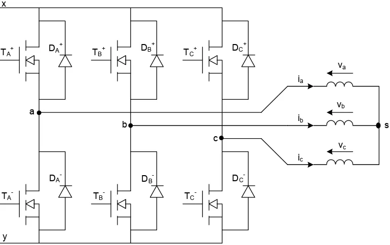
1.3). This implies that BLDC motors are normally three-phase wound with each motor line current controlled by one leg of the three-phase bridge. The inverter is operated in PWM mode with two out of the three-phase windings energized at any one time. Figure 1.4 displays idealized phase currents supplied by the inverter. Note that ideally there are six commutation states in one cycle of operation. These have been labelled CB, AB, AC, BC, BA and CA.
DA + TA+
TA
-DA- DB
-DB +
DC +
DC
-y a
b
c
s
ic
vc vb TB+
TB
-TC+
TC
-va
ib ia x
[image:36.595.128.513.287.529.2]Note: 3-phase windings assumed star connected, some BLDC motors are delta connected.
CHAPTER 1. INTRODUCTION 6
Figure 1.4 : Idealised Currents Supplied by Inverter
Phase current reversals have to be initiated at rotor angular positions θ1, θ2, θ3, θ4, θ5, and θ6. The
CHAPTER 1. INTRODUCTION 7
back EMF of the unenergised phase. The commutation controller relies on the fact that the ideal commutation position lags the back EMF zero crossing position by thirty electrical degrees [2,3]. As mentioned before the major problem with the back EMF method is its ineffectiveness at or near zero speed.
There is currently significant research work aimed at developing improved sensorless techniques for brushless motors. Many of the suggested methods are based on inductive saliency. The recently suggested equal inductance method [2, 3] has proven to be very effective and, when used together with the back EMF technique, meets performance requirements over very wide speed ranges down to zero speed.
1.3
Background Information on Printed Circuit BLDC
Motors
CHAPTER 1. INTRODUCTION 8
mode is much simpler and cheaper and meets the performance requirements of most applications. The focus of this thesis project is on printed circuit BLDC motors.
There is a major difference between the coil configuration used in the original printed circuit motors and the coil configuration in modern printed circuit stators. In the original design, as shown in figure 1.5, every printed track is nominally identical to every other track except for a displacement by one track pitch (analogous to the slot pitch in conventional wire wound machines). The coil configuration illustrated in figure 1.5 is normally called a “wave winding”. In the modern design the printed coil is usually spirally shaped. This means that the length of the active sections of tracks become progressively smaller towards the centre of the spiral. An example is shown in figure 1.6. The advantage of using a spirally shaped coil is simplicity and also it is much easier to accommodate a spiral coil within a stator having small radial dimensions.
CHAPTER 1. INTRODUCTION 9
Unfortunately there are only a few publications on printed circuit stators with spirally shaped coils. It appears that up to now researchers have not yet developed systematic methods for the design and production of printed circuit stators. Some qualitative statements have been made about the use of rhomboidal shaped turns to reduce copper loss, but the negative effect that this could have on torque capability has not been considered. Rhomboidal turns, as shown in figure 1.6, also leave significant unused areas on the substrate between neighbouring coils. Note that spirals exist in pairs on adjacent printed circuit layers. This allows the central terminal of one spiral to be series connected to the central terminal of another spiral located on the adjacent printed circuit layer. Thus the total number of layers is always even. There may well be better options than rhomboidal turns. A number of patented printed circuits make better use of the area of the substrate by using coils whose active sections follow lines that are parallel to the radial line separating neighbouring coils. Throughout this document these will be termed as “coils with parallel tracks”. An example is shown in figure 1.7. Potentially coils with parallel tracks can result in higher torque output than equivalent machines with rhomboidal coils. But this remains to be proven.
CHAPTER 1. INTRODUCTION 10
Figure 1.7 : Coils with Parallel Active Sections
CHAPTER 1. INTRODUCTION 11
Figure 1.8 : Coils with Radial Active Sections
CHAPTER 1. INTRODUCTION 12
Figure 1.9 : Distribution of Coil on one Printed Circuit Layer (‘Four-Pole’ Flux Distribution)
Figure 1.10 : Exploded View of a Printed Circuit Axial Field Brushless Motor
Rotor Disks
Permanent Magnets Y position [m]
0.01
0
-0.01
-0.02
-0.03
0.02
0 0.01
-0.01
-0.02
0 0.02
-0.02
Shaft Substrates
Z position [m]
CHAPTER 1. INTRODUCTION 13
The other way of implementing a printed circuit stator would be to have all three phases sharing every printed layer. This means that the number of coils per layer must be a multiple of six. A feature of this stator design is that the stator coil pitch is generally different from the rotor pole pitch.
The following are some of the important variables that have to be considered in order to arrive at an optimum printed stator design for a given application.
(a) Number of rotor poles
(b) Stator coil shape (wave wound, rhomboidal, radial or parallel)
(c) Nature of printed layers (each equally shared between phases or single phase per layer) (d) Number of layers
(e) Track thickness (f) Track width (g) Track clearance
(h) Insulation material and insulation thickness (i) Substrate material and substrate thickness
(j) Number of substrates that make up the stator stack
CHAPTER 1. INTRODUCTION 14
1.4
Sensorless Operation
Printed circuit brushless DC motors are relatively small motors and they are more likely to be cost competitive if they can operate without position sensors. The back EMF zero crossing method may be a good choice if good performance during starting and at low speeds are not critical requirements. As back EMF is proportional to speed, the method does not work at and near zero speed. Satisfactory sensorless operation at low speed and during start-up is possible only by implementation of special techniques. One way of addressing the commutation problem at start-up and at low speeds is to supplement the back EMF method with the “equal inductance
method” [2]. The latter method relies on the variation of stator inductance with rotor position. This variation is characterised by the so-called saliency ratio of the machine. The method is called the “equal inductance method” because detected positions of equal inductance of the energised phase pair are used to determine the next commutation instant. While the equal inductance method has been found to work with wire-wound motors having saliency ratios of 1.1 or more, it is not clear whether the method would work with printed circuit motors. The significant differences between the characteristics of printed circuit machines and those of wire-wound machines suggest that modifications of the originally proposed equal inductance method would most likely be necessary for it to work with printed circuit motors.
CHAPTER 1. INTRODUCTION 15
theoretical determination is not straightforward. The brute force approach to theoretical determination of inductance would require detailed three dimensional non-linear electromagnetic magnetic modelling under quasi static conditions. Typically such modelling would be carried out using the finite element method. However, this approach does not suit many designers because of lack of the necessary skills or computational resources. Also, due to the necessity for iterative analysis to arrive at optimal designs, computer processing time may also be too long. There is a need to develop sufficiently accurate but fast and computationally efficient techniques for determining printed circuit motor self and mutual inductances.
1.5
Thesis Project Objectives
It is very likely that printed circuit motors will be used in an increasing number of modern applications. However, there seems to be a lack of systematic design tools to assist printed circuit motor designers. Also, to the author’s knowledge, there is no published work that specifically addresses the question of sensorless operation of printed circuit BLDC motors down to zero speed. The need to address those identified gaps has led to the following objectives for this thesis project:
(a) to develop guidelines and a theoretical basis for the optimum electromagnetic design of axial field printed circuit brushless DC motors;
CHAPTER 1. INTRODUCTION 16
(c) to develop a position sensorless commutation method for axial field printed circuit brushless DC motors that is effective down to zero speed;
(d) to experimentally validate the position sensorless commutation technique that is developed as part of this thesis project and
(e) to develop a computationally efficient modelling technique that would allow prediction of the self and mutual inductances of the phase windings of axial field printed circuit brushless DC motors;
1.6
Outline of Dissertation
A review of the published works that are of relevance to the thesis project objectives is presented in chapter 2. Details of the thesis project methodology and the reasoning behind it are given in the same chapter.
Chapter 3 is devoted to the development of tools to help with the optimum design of printed circuit board stators. These tools include computer algorithms for automatic stator track plotting and phase EMF waveform prediction. The mathematical basis for the algorithms and their experimental validation are also included.
CHAPTER 1. INTRODUCTION 17
inductance method. Experimental results which validate the enhanced equal inductance method are presented. The modified method, unlike the originally proposed method, does not require a neutral connection.
The originally proposed equal inductance method assumes that the motor being controlled is nominally symmetrical. Chapter 5 presents the mathematical arguments which were used to arrive at a generalised equal inductance method applicable to the inherently asymmetric class of printed circuit BLDC motors that was the focus of this thesis project. Experimental results which confirm the validity of the generalised method are also presented.
Eddy currents induced within the stator tracks of printed circuit machines represent a parasitic load and cause increased stator heating. In chapter 6 a mathematical model is proposed to quantify stator eddy current loss. A specially designed laboratory test procedure is described which has allowed predictions made by the model to be verified.
Chapter 7 presents fast and computer resource efficient mathematical algorithms that allow stator winding inductances to be theoretically evaluated. Predictions made using the algorithms have been experimentally verified. The computer algorithms can be used by designers, before construction of physical prototypes, to check that sufficient inductive saliency is present for successful application of the equal inductance method.
CHAPTER 1. INTRODUCTION 18
1.7
Main Outcomes of the Thesis Project
This thesis project has resulted in a number of useful outcomes for printed circuit board machine designers. Analytical tools have been developed and validated to assist with optimisation of printed stators. Designers will be able to maximise output torque while satisfying requirements for maximum track width, minimum track width and inter-track clearance. In particular a technique has been developed for quantitative assessment of eddy current losses within copper tracks. Theoretical findings of the thesis project can be embedded into computer software for quick assessment of the effect of changes in important design parameters such as stator dimensions and pole numbers. It is also possible to use the developed design tools to explore ways of reducing stator losses and improve efficiency without compromising torque capability.
CHAPTER 1. INTRODUCTION 19
led to a simplified electromagnetic model that allows saliency ratio and winding inductances to be estimated by means of computationally efficient techniques.
An interesting point is that the equal inductance method was originally developed for nominally symmetrical three phase machines. This thesis project dealt with an important class of printed circuit machines which exhibits significant asymmetry. A significant outcome has been a generalised equal inductance method that takes into consideration phase asymmetry.
The following journal papers, that have been published or accepted for publication, are direct outcomes of this research project.
Ahfock A., Gambetta D., ‘Stator Eddy Current Losses in Printed Circuit Brushless DC Motors’, Electric Power Applications, IET Proceedings, (accepted for publication)
Ahfock A., Gambetta D., ‘Sensorless Commutation of Printed Circuit Brushless DC Motors’, Electric Power Applications, IET Proceedings, (accepted for publication)
CHAPTER 1. INTRODUCTION 20
21
Chapter 2
Literature Review and Methodology
2
2.1
Literature Review
The purpose of the literature review was to find out about:
(a) any previously published work on design optimisation of printed circuit board motors; (b) previously suggested techniques for low speed sensorless commutation control of
brushless motors that could be useful with axial field printed circuit BLDC motors; (c) computational electromagnetic methods that could help with prediction of performance
of axial field printed circuit motors and
CHAPTER 2. LITERATURE REVIEW AND METHODOLOGY 22
2.1.1 Printed Circuit Motors
To date publications on printed circuit motors, such as references [6] to [10] have been limited to:
(a) motors, with output torque of the order of a few milli-newtonmetres or less than 1 watt per krpm, meant for applications such as computer drives and handheld video cameras; (b) prediction of torque or back EMF for motors of predetermined coil configuration and
dimensions such as magnet thickness, rotor back-iron thickness and rotor-to-stator axial length ratio.
In contrast, motors with power ratings up to tens of watts per krpm are being considered in this thesis project. It seems that the requirement to keep axial thickness to a minimum has led designers of axial field printed circuit to share printed circuit layers among all three phases. As part of this thesis project, investigations will be carried out to find out whether this approach is detrimental to electromagnetic torque production. There has been no rigorous analysis performed to support the idea that rhomboidal coils represent the optimum coil configuration for axial flux printed circuit motors. Systematic printed circuit board design algorithms will be developed as part of this thesis project. These will allow the best coil configuration to be chosen for given dimensional specifications of the motor space envelope.
CHAPTER 2. LITERATURE REVIEW AND METHODOLOGY 23
concentric shape with radial or near radial active sections and with circumferential end sections. No reasons are given for their choice of coil shape or their number of turns.
Tsai and Hsu [7] propose an analytical technique for prediction of air-gap flux density which is verified by experiment and by using FEA. Their analytical method does not take into consideration rotor back iron saturation and they do not specify if their three-dimensional FEA does. They point out the better suitability of the rhomboidal printed coil for stators of low radii. They also claim that the rhomboidal shape results in lower I2R loss. However, no quantitative analysis is presented to support that claim. In particular there is no mention of whether the benefit of lower I2R loss is gained at the expense of lower output torque capability.
Jang and Chang [8] present a relatively simple permeance model to predict the average airgap flux density in axial field printed motors. The model is based on three permeance branches, one for the axial path along the mechanical air-gap and printed coil, one for the axial path through the magnet and one representing leakage paths. The calculated average air-gap flux density is used to predict values for output torque for given coil currents. These compare well with measured values. Details of any methodology used for designing the stator are not mentioned.
CHAPTER 2. LITERATURE REVIEW AND METHODOLOGY 24
values of flux density in the mechanical air-gap, printed circuit layers and iron cores. The one-dimensional model is used to determine the required magnet thickness. There is no mention of a systematic procedure aiming at design optimisation.
To the author’s knowledge there are no publications on a design procedure for axial flux printed circuit motors where the electromagnetic design of the stator and that of the rotor are simultaneously and systematically considered. In a typical application the space envelope for the motor is usually specified in terms of a maximum radius and a maximum axial length. The challenge for the designer is to produce a design that would meet torque output requirements and that would fit in the specified envelope. The given axial length has to be shared between the motor housing, the clearance between the motor housing and the rotor iron, the rotor back-iron axial thickness (2ti), the permanent magnet axial thickness (2tm), the mechanical air-gap
axial length (2tag) and the stator axial thickness (ts). All the listed axial lengths may be
considered fixed except ti, tm, and ts. Since the total axial length is usually specified, the sum of
ti, tm, and ts would have to be equal to or smaller than a given value. This means that they cannot
be independently chosen. Takano, Ito, Mori, Sakuta and Hirasa [10] arrive at an optimum value of 2 for tm/ ts for wire-wound machines. The existence of an optimum ratio is easily explained.
Torque is proportional to the product of the air-gap flux density set up by the permanent magnets and the stator current. A relatively large value of tm would also require a relatively large value
of ti to avoid rotor back iron saturation. The choice of an excessively large value of tm leaves
very little room for a stator with reasonable current capacity and this leads to low torque rating. On the other hand choosing an excessively large value of ts to boost current capacity leaves very
CHAPTER 2. LITERATURE REVIEW AND METHODOLOGY 25
density and low torque rating. There is clearly an optimal value of tm/ts . That optimum ratio
may be a function of other motor parameters. As part of this thesis project, generalised algorithms will be developed to identify optimum tm/ts ratios for printed circuit axial field
motors.
For a given voltage rating, as the power rating of printed circuit stators increase, their printed tracks would tend to be wider. For a fixed conductor thickness a wider track would not necessarily mean a proportionately higher current carrying capacity since the track would also suffer from increased circulating or eddy currents. The problem of eddy currents within stator conductors of wire-wound machines has been previously analysed [11, 12]. However, to the author’s knowledge, there is no publication on eddy currents induced in the conducting tracks of a printed circuit stator.
CHAPTER 2. LITERATURE REVIEW AND METHODOLOGY 26
2.1.2 Sensorless Operation
It is advantageous to design printed circuit brushless motors so that they can be operated as sensorless brushless DC motors. Sensorless position detection methods that have been proposed to date for BLDC motors fall into two categories. There are those based on the use of back EMF signals and those based on exploitation of inductive saliency. Back EMF based methods are only applicable if speed is high enough. Nevertheless, there are many applications, for example drives for fans or pumps, that do not require position control or closed-loop operation at low speeds. For these, a back EMF based method is quite appropriate. Widely used, is the so called back EMF “zero crossing” method, where the zero crossing instants of the un-energised phase are used to estimate position [13]. It is important to mention that there is a 30° (electrical) offset between the back EMF zero-crossing and the required commutation instant, which must be compensated for to ensure correct operation of the motor [2,3].
CHAPTER 2. LITERATURE REVIEW AND METHODOLOGY 27
[22] propose position detection techniques, based on saliency, specifically for BLDC motors and they reduce complexity by exploiting the availability of an unexcited phase. But they also rely on imposition of special signals onto the stator windings. Imposition of special signals requires additional electronics, can cause additional heating and deterioration of torque quality.
CHAPTER 2. LITERATURE REVIEW AND METHODOLOGY 28
stator stack does not have the same inductance as the other two phases. Also the phase winding time constant is relatively low because the stator is iron-less.
2.1.3 Measurement of Inductances and Inductive Saliency
CHAPTER 2. LITERATURE REVIEW AND METHODOLOGY 29
CHAPTER 2. LITERATURE REVIEW AND METHODOLOGY 30
possible to those of normal operation. Based on this, it was assumed that inductances measured with the rotor stationary and using sinusoidal currents at the inverter PWM frequency will be those that are relevant to the equal inductance method. As part of this thesis project, laboratory tests have been carried out to confirm the validity of this assumption. These tests consisted of a comparison between absolute position determined by the equal inductance method which is itself based on inductance values and those that are measured by a position sensor.
2.1.4 Prediction of Inductances and Inductive Saliency
Section 2.1.3 has focussed on measurement of saliency ratio or inductances that are applicable to the equal inductance method. A related question is the prediction of those inductances at the design stage of a brushless DC motor. Such information would be useful to those who intend to use the equal inductance method but do not have access to the motor because it is yet to be constructed.
CHAPTER 2. LITERATURE REVIEW AND METHODOLOGY 31
A computational electromagnetic method which is not as popular as FEA is the coupled network method [39-51]. In its standard form, the method consists of a set of magnetic nodes and a set of electric nodes. The nodes are located in 3-D space forming a regular pattern and are joined by branches. The electric and magnetic nodes do not normally coincide. The magnetic branches are reluctive and the electric branches are resistive. Loops formed by the magnetic branches link loops formed by electric branches and vice-versa. Note that currents flowing in the electric network may be induced or imposed. The branch reluctances and the branch resistances are assumed to be known. The two networks are simultaneously analysed by a sets of node and/or loop equations which are based on Maxwell’s Laws. An advantage of the coupled network method is that it is amenable to physical interpretation [47, 48, 52]. Unfortunately, the coupled network method, with no assumptions made about flux and current paths, is more restrictive than the finite element method (FEM). The number of nodes required is generally more than the number needed with FEM. It is a method that can be applied to simple geometries only.
CHAPTER 2. LITERATURE REVIEW AND METHODOLOGY 32
The adopted computational technique for the determination of inductance will be based on a standard regular 2-D network of nodes and branches representing the magnetic field and a set of assumed 1-D current paths making up the electric network. The two-dimensional approximation of the magnetic field and the simplification of the current distribution to a set of one-dimensional paths greatly improve computing efficiency. The physical reasoning behind the approximation and simplification is presented. Tests have been carried out to validate the proposed technique of inductance evaluation.
2.2
Methodology
The choice of thesis project methodology was influenced by the requirement to design cost competitive BLDC motors with ratings in the range of tens of watts per krpm that:
(a) could be manufactured using standard modern printed circuit manufacturing processes; (b) would fit in a space envelope defined by an axial length and a radius; and
(c) could be operated down to zero speed by means of a simple position sensorless commutation technique such as the equal inductance method.
2.2.1 Design options and procedure
CHAPTER 2. LITERATURE REVIEW AND METHODOLOGY 33
conducting material for the conducting track are silver and copper. It was quickly ascertained during the early stages of the thesis project that FR4 substrates with copper tracks represented the most practical and most economic option. FR4 copper clad laminate are widely available commercially with a number of standard FR4 and copper thicknesses. Other relevant variables in the manufacture of printed circuit boards are the number of printed circuit layers per substrate, minimum track width, minimum clearance between tracks and track thickness. The cost of manufacture depends non-linearly on the number of circuit layers. The cost of multi-layer printed circuit boards escalates rapidly as the number of layers grows. It was found that beyond eight to twelve layers per substrate the manufacturing costs of circuit boards become too prohibitive for them to be used in motors. Consequently it was decided to keep the maximum number of printed layers per substrate to eight. It was also decided to use standard commercial track thicknesses to keep cost to a minimum. Minimum clearances used were those recommended by FR4 laminate manufacturers. Those minimum clearances are a function of copper track thickness. It should be noted that while decisions were made to use standard track thicknesses, the design algorithm that was developed will allow the option of exploring non-standard thicknesses.
CHAPTER 2. LITERATURE REVIEW AND METHODOLOGY 34
value to its d-axis value is also closer to sinusoidal. Sinusoidal variation of inductance is an important requirement of the equal inductance method which is planned to be used.
It was also decided to have one substrate per phase, as shown in figure 1.9. This allowed designs with a larger number of layers per phase without exceeding the previously stated eight layers per substrate.
Table 2.1 shows a list of the main design variables that had to be considered. These variables have been divided into four groups. The first group, made up of the variables 1 to 5, are design specifications. The assumptions are that they are fixed and that the objective is to arrive at a design that achieves maximum output torque while respecting the constraints in Table 2.1.
The second set of variables, numbered 6 to 14, are essentially data that are associated with the materials that have been selected by or provided to the designer for the manufacture of the motor being designed. The design procedure is based on the assumption that those variables are fixed. However, the designer may wish to go through the design procedure a number of times, each time with one or more of those variables changed. For example, given the design specifications, the design procedure could be separately used to arrive at the best design with different FR-4 laminates. This would allow the FR-4 laminate that gives the best design to be selected.
CHAPTER 2. LITERATURE REVIEW AND METHODOLOGY 35
The last group of variables, labelled 17 to 20 in Table 2.1, are outcomes of the planned design procedure. The procedure is illustrated in figure 2.1. There are several iterative loops. Two of those are shown explicitly. The determination of the minimum back iron thickness ti is
performed iteratively by changing ti and conducting non-linear 3-D magnetostatic analysis for
each value of ti. The search is for the minimum value of ti that results in the specified maximum
allowable flux density in the rotor back-iron. Note that the term ‘iteratively’ is being used to also cover what is in essence a one-dimensional search for a value that satisfies a particular design specification. For example tm is incremented from a minimum value and for each value the motor
torque capability is calculated. In this case the one dimensional search is for the value of tm that
CHAPTER 2. LITERATURE REVIEW AND METHODOLOGY 36
Table 2.1 : Main Printed Circuit Motor Design Parameters
Design Parameter Degree of Flexibility
1 Outer Radius (Ro)
Fixed specified value, dependent on intended application and considered to be a design specification
2 Inner Radius (Ri)
Fixed specified value, dependent on intended application and considered to be a design specification
3 EMF (at 1000 rpm)
Fixed specified value together with tolerance, for example: 1V ± 10%. Considered to be a design specification that is dependent on the intended application
4 Total axial length (ta)
Fixed specified value, dependent on intended application and considered to be a design specification
5
Stator/Magnet Clearance(tc)
Fixed specified value, typically 0.3 mm
6
FR4 insulation layer thickness
Fixed specified value obtained from data sheet of chosen FR4 / Cu laminate
7 Track thickness
Fixed specified value obtained from data sheet of chosen FR4 / Cu laminate
8
Clearance between tracks
Fixed specified value obtained from data sheet of chosen FR4 / Cu laminate
9 Minimum track width
CHAPTER 2. LITERATURE REVIEW AND METHODOLOGY 37
10
Max allowable stator power loss (Pl)
Fixed specified value dependent on stator material thermal properties, stator dimensions and maximum allowable temperature rise. This value is obtained from the one-dimensional thermal model.
11
Minimum Magnet thickness
Fixed specified value from supplier, typically 1 mm
12
Incremental change between consecutive standard
magnet thicknesses
Fixed specified value obtained from magnet supplier, typically 0.25 mm
13 Remanence (Br)
Fixed specified value from data sheet of chosen magnet, typically about 1.2 T
14
Rotor peak flux density (Bs)
Fixed value dependent on chosen rotor steel. Typical value is around 1.4 T. Value obtained from steel supplier or by test on a sample.
15
Number of rotor poles (P)
CHAPTER 2. LITERATURE REVIEW AND METHODOLOGY 38
16 Coil shape
To be an output of the design procedure. For dimensions of Ro and Ri normally under consideration, the best coil shape will most
likely have parallel active sections or mixed parallel and radial sections.
17
Rotor Iron thickness (ti)
To be an output of the design procedure, but should be greater than 1 mm to ensure adequate mechanical strength.
18
Magnet thickness (tm)
To be an output of the design procedure. However only discrete values above a minimum is allowed. The discrete values and the minimum value depend on the chosen supplier.
19
Number of turns per coil (N)
To be an output of the design procedure
20
Number of printed circuit layers per phase (L)
CHAPTER 2. LITERATURE REVIEW AND METHODOLOGY 39
CHAPTER 2. LITERATURE REVIEW AND METHODOLOGY 40
Inspection of table 2.1 and figure 2.1 reveals that a number of tools are to be developed to implement the design optimisation procedure. These are:
(a) A 1-D thermal model to calculate, using material data, the maximum allowable stator power loss;
(b) A technique for the measurement of the magnetising curve of samples of the steel that is used for the rotor;
(c) Computer algorithms to automatically plot coil tracks;
(d) Computer algorithms to automatically determine phase EMF waveforms;
(e) A mathematical model to predict eddy current loss in stator copper tracks. There is a need to ensure that stator tracks are below the width that would cause excessive eddy currents.
Prototypes will be specially designed to validate theoretical predictions made in (d) and (e) above.
2.2.2 Modification and adaptation of the equal inductance method
CHAPTER 2. LITERATURE REVIEW AND METHODOLOGY 41
been tried with motors with low phase inductance. The plan was to further develop the equal inductance method so that it does not need a neutral connection and to adapt it so that it is compatible with the ironless printed circuit axial field machines. Since the equal inductance method cannot work successfully without a minimum level of saliency there is a need for a mathematical procedure to predict inductance and saliency at the design stage.
Considering the points presented in the preceding paragraph the following were planned:
(a) Theoretical analysis to confirm that the equal inductance method, if suitably modified, will work without a neutral connection;
(b) Confirmation, by laboratory tests performed on standard radial field wire-wound motors, that the modified equal inductance method performs well both at steady state and during starting;
(c) Measurement of the inductance and mutual inductance characteristics of printed circuit machines such as the one illustrated in figure 1.9 to ascertain the nature of further modifications that would be necessary to adapt the equal inductance method to suit those motors;
(d) Development of the necessary further modification of the equal inductance method to make it suitable to printed circuit motors. This would be based on theoretical analysis. (e) Assessment of performance of the adapted equal inductance method by carrying out
CHAPTER 2. LITERATURE REVIEW AND METHODOLOGY 42
43
Chapter 3
Printed Circuit Stators for Brushless
Permanent Magnet Motors
3
3.1
Introduction
CHAPTER 3. PRINTED CIRCUIT STATORS FOR BRUSHLESS PM MOTORS 44
printed circuit tracks to be carried out more systematically. Track plotting procedures have been developed for four different coil shapes.
These are spirals with purely radial active sections, spirals with active sections running parallel with each other, spirals with each active section having a radial part and a parallel part and rhomboidal shaped spirals. For each spiral shape, equations are derived for the maximum number of turns (N). The maximum number of turns is generally a function of the substrate inner radius (Ri), the substrate outer radius (Ro), the track minimum width (w) and the minimum
CHAPTER 3. PRINTED CIRCUIT STATORS FOR BRUSHLESS PM MOTORS 45
3.2
Analysis of Coil Geometries
CHAPTER 3. PRINTED CIRCUIT STATORS FOR BRUSHLESS PM MOTORS 46
a)
b)
CHAPTER 3. PRINTED CIRCUIT STATORS FOR BRUSHLESS PM MOTORS 47
In general each turn of a coil may be considered to be made up of four sections. Two of those are non-active arc-shaped end-sections, one on the outer radius side and one on the inner radius side. The other two sections are active. The length of some of the arc-shaped inner end-sections may degenerate to zero for low values of Ri/Ro. To maximize the effectiveness of a coil its number of turns, average active length per turn and overall pitch factor must be maximized. Assuming the air-gap flux is purely axial, the maximum EMF per unit length is obtained if the active conductor runs along a radial line. However, the number of turns can be adversely affected if Ri/Ro is small
and the active sections are constrained to be radial. Parallel active sections are preferable although this leads to longer inactive sections. Coils with active sections which are partly parallel and partly radial are investigated because they offer the possibility of reduced total conductor length while maintaining performance in terms of EMF per unit speed or torque per unit current. Expressions are now derived for the maximum number of turns.
3.2.1 Purely Parallel Coils
In figure 3.2 (a) point X is at the centre of the coil and lies somewhere along the radial line which is the axis of symmetry of the coil. Proper placement of point X is required if a coil with maximum number of turns (N) is to be achieved. In general for given values of minimum track width (w) and minimum inter-track clearance (c), the number of turns is limited by (Ro-Rx) or
XP or (Rx-Ri). If X is placed too far towards the outer edge of the substrate, N is reduced
because it becomes restricted by the smaller value of (Ro-Rx). Similarly, if X is placed too far
CHAPTER 3. PRINTED CIRCUIT STATORS FOR BRUSHLESS PM MOTORS 48
P
X
Rx Ro
Ri
s N
π
Figure 3.2(a) : Half Spiral Section of Substrate
Figure 3.2(b) : Example of Printed Coil with Parallel Tracks
-0.0250 -0.02 -0.015 -0.01 -0.005 0 0.005 0.01 0.015 0.02 0.025 0.005
0.01 0.015 0.02 0.025
X position [m]
Y
p
o
s
it
io
n
[
m
]
Track middle line
CHAPTER 3. PRINTED CIRCUIT STATORS FOR BRUSHLESS PM MOTORS 49
Based on the preceding arguments, it can be concluded that there is a position for X that results in the maximum number of turns. For small values of Ri/Ro, the number of turns is maximized if:
(
)
= − s x x o N R RR sin π (3.1)
where Ns= number of spirals per layer
For larger values of Ri/Ro, the number of turns is maximized if:
(
R
o−
R
x) (
=
R
x−
R
i)
(3.2)That is the optimum value of Rx is
(
)
2
o i
R
+
R
From equation (3.1) it can be deduced that:
(
)
+ + = s s o N c w N R N π π sin 1 sin (3.3)Equation (3.3) is applicable if:
+ − ≤ s s o i N N R
![Figure 1.1 : BLDC Rotors with Surface Magnets (Source: reference [1])](https://thumb-us.123doks.com/thumbv2/123dok_us/203148.55583/34.595.232.409.548.643/figure-bldc-rotors-surface-magnets-source-reference.webp)