BASF Aktiengesellschaft
B A S F 6 1 3 8 M I N I DISK DRIVE
Mannheim, April 1983
VID/WMS Spec.Nr. Rev. 01 80307-058
CONTENTS
...
1
.
Product Outline 11-1 Feature
...
11-2 Specifications
...
1...
.
2 Interface 4...
2-1 Signal Interface 4 2-2 Table of Connector Used...
52-3 Input/Output Interface
...
62-4 Timing Chart
...
102-5 Multiple Drive Connection System
...
133
.
Description of Functions..
...,...
14...
3-1 Overall Block Diagram 14 3-2 Circuit Block Diagram...'...
143-3 Jumper Functions
...
14...
3-4 Arrangement of Jumper Pins 15.
...
4 Dimension Specifications 16 4-1 Installation Method...
16...
4-2 Exterior of Unit 17
...
5
.
Handling Mini Floppy Disks 18.
...
1. Product Outline 1-1 Feature
This MDD employs a high performance direct-drive spindle
motor, resulting in stability of media rotation and also freedom from maintenance due to the elimination of a
driving belt. It also employs a high-speed stepping
motor and steel belt drive system, permitting speedier
seek-access by the head, and making for improved track
positioning accuracy.
1-2 Specifications
1-2-1 Performance
Note 1: The waiting time during seek is the track-to-track
shift time
+
seek settling time.Note 2: The average access time is the average track-to-
track shift time + seek settling time.
Recording density per diskette
per track Data transfer speed
Access Track-to-track shift time
time Seek settling time
Average access time Head load waiting time Media rotating speed
Average rotation waiting time spindle motor starting time
Recording density (inner periphery) Number of tracks
Modulation system
Recommended media
MDD221
1M byte
6.25K byte 250K bit/sec
3ms MAX 20ms MAX
9 Sms
25ms MAX
300 rpm looms 1s MAX 5922 BPI 160 FM/MFM
BASF FlexyDisk
1-2-2 Boundary Conditions
1-2-3 Power Source
Operating ambient temperature
Temperature during
' transport
Storage temperature Relative humidity
5
-
45OC-40
-
62OC -22 -.5S°C20% to 80% (max, wet bulb temperature 2 g ° C , free of dew formation)
1-2-4. Machine Dimensions +5V 5 5 %
ripple 50 mVp-p and below +12V + 5 %
ripple 100 mVp-p and below -
TYP 0.8~'
1- 1.OA TYP 0.8A
MAX 1.7A
*
For details, refer to dimension specifications. WidthHeight Depth Weight
146 mm
33.5 mm
221 mm
1-2-5 Vibration and Shock
1-2-6 Reliability
vibration during operation
VibratFon during transportation
shock during transportation
1G (5
-
100Hz)X, Y, and Z directions
3G (5
-
100Hz)X, Y, and Z directions
(in packed condition)
Shall satisfy all specifics- tions when dropped from a height of lOOcm in packed condition (in all directions, one corner, three ridgelines, and six planes)
MTBF
MTTR
Unit life
Soft read error
Hard read error
Seek error
10,000 POH
30 minutes
5 years
10- bits
10' 12 bits
2. I n t e r f a c e
2 - 1 S i g n a l I n t e r f a c e
M I N I F L O P P Y
HOST SYSTEM DISK DRIVE
t
HEAD LOAD
-
RESERF,
SELECT 3 -
INDEX
.
SELECT 0 -
SELECT 1
11 I I l FLAT RIBON or TWISTED
P A I R
i
%
,
TWISTED P A I R
10
a '
12 4 1
3
1 1 5
117 9 I/O , I ,, GND
F GND
SIDE S E L E ~
I READY
-
+ 5 V +12 V
32
3 4
4
1 0 3 1
1133
Power
supply
con-
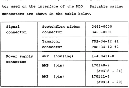
2-2 Table of Connector Used
Figs. 2-1 and 2-2 are simplified drawings of the connec- tor used on the interface of the MDD. Suitable mating connectors are shown in the table below.
Fig. 2-1 Signal connector
3463-0000 3463-0001 FDS-34-12 #1
FDS-34-12 #2 1-480424-0 170148-2
(AWG18
-
24) 170121-4(AWG14
-
20) Signalconnector.
Power supply connector
Scotchflex ribbon connector
Yamaichi connector
AMP (housing) (pin)
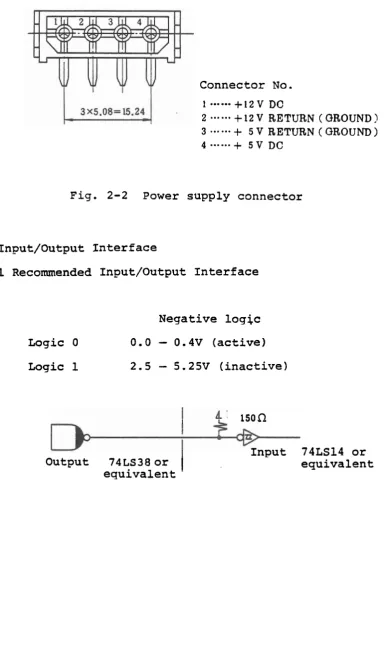
[image:9.595.108.527.126.412.2]Connector No.
...
1 +12 V DC
2
...
+
12 V RETURN ( QROUND !3
...
+
5 V RETURN ( GROUND )4
...
+
5 V DCFig. 2-2 Power supply connector
2-3 Input/Output I n t e r f a c e
2-3-1 Recommended Input/Output I n t e r f a c e
Logic 0
Logic 1
Negative l o g j c
0.0
-
0.4V ( a c t i v e )2.5
-
S.25V ( i n a c t i v e )lSOQ
Input 74LS14 o r
Output 74LS38 o r e q u i v a l e n t
2-3-2 Input Signal Name
Signal name
Select 1 to 4
Motor ON Direction in Step Write gate Content
It is possible to connect up a maximum of four MDD units in a daisy chain.
Set the drive select condition by means of the
drive jumper pin. (All units are set to drive
select 1 before they leave the factory.)
When the select signal of the set drive becomes
low level, the drive will go into an active condition.
When this signal becomes low level, the drive motor will rotate. The motor signal alone is not gated by the select signal.
When this signal is high'level, the head will
shift to the outer periphery under the step .signal. When it is low level, it will shift
to the inner periphery.
This signal is a pulse signal. The head will
shift. in the direction of the 'direction in'
signal under the leading edge (fall) of this pulse.
When the write gate is on, internally it goes into an inhibit condition.
Signal name
Write data
Head load
Side selector
Ready
Track 00
Content
This signal is a pulse signal. Under the
leading edge of the pulse (fall), the data
will be inverted and information will be registered in the media.
Transfer data only when the write gate is low level.
When this signal becomes low, the head will be loaded. It is also possible to perform head loading by means of the drive selector signal, irrespective of the head load signal. During
head,load, the indicator LED becomes red and
the button is interlocked. For details, see the jumper specifications.
This signal is used to select a particular head on a drive employing a double sided head. When it is high level, head 0 is selected, and when it is low level, head 1 is selected.
After the motor goes on and the media reaches a constant speed of rotation, this signal will
go on (low level)
.
After a lapse o f . 1 second from when the motor
goes on, the ready signal is confirmed and
i?/W operation commences. Then, the indica-
tion LED becomes green..
*
All output signals are gated by the drive select signal. Signal nameIndex
Read data
Write protect
Content
This signal goes on (low level) when the index hole of the media is detected.
This signal is a 3 to 5 ms pulse signal.
The leading edge (fall) of the 'pulse indicates
the commencement of the trac.k/sector.
When the media is not inserted, this signal will remain low level.
This is a reado,ut signal for magnetic inver-
sion on the media. It is a pulse signal, the leading edge (fall) of which is effective.
This signal becomes low level when a write- protected media is inserted. Simultaneously, write will be inhibited inside the drive.
-Write protect takes place by covering the
2-4 T i m i n g C h a r t
2 - 4 - 1 R e a d y S i g n a l T i m i n q
Effective area
4
M o t o r ON
500 ms ( MAX)
Select 1 t o 4 ( I N ) ( I 1
R e a d y (OUT)
Index
Ineffective-
/////d area
T r a c k 0 0 (OUT)
Write p r o t e c t (OUT)
R e a d data
1
I
I
I
(OUT) (OUT)
2-4-2 S t e p S i g n a l Timing
-
%
Select 1 t o 4 ( I N )
S t e p
-
-
D i r e c t i o n i n ( I N )
-
Ips (MIN)1ps (MIN)
2-4-3 Readout Timing
Select 1 to 4 (IN)
I
I
Ready Step
(OUT)
Side select (IN)
1 .
I
(IN)
Effective data
Head load (IN)Note 1
I
2-4-4 Write Timing
Ready
I p s M I N 1.2ms MIN
Step
1.2ms MIN
1.2 ms MIN
Write gate (IN)
I
*
HSelect 1 to 4 (IN)
Write data
2 5 m s MIN
Head load (IN)Note 1
- -
Note 1: The necessary head load waiting time is 25ms from thecommencement of actual head loading.
2 - 4 - 5 Read D a t a (OUT)
2-4-6 Write Data (IN)
* B P S - -
M F M
-
e 8W -4m I
-
T 6Ps-
-. 200ns MINA 4,Us
-
L
6,Us-
1 -
5 0 0 n s k 2 O $-
--
Use a write clock accuracy of 20.5% (4ps+20ns).
NOM N O M I NOM I
2-5 Multiple Drive Connection System
When connecting several MDD units to a host system,
either a radial connecting method or a daisy chain
connecting method is used.
When using the daisy chain connecting method, it is necessary to remove all pull-up resistors (resistor arrays) except that on the last MDD unit.
S i g n a l
/
1
DC w e supplyRadial connection
M S i g n a l .
*
Remove r e s i s t o r a r r a y s . Host system,:Daisy chainconnection S i g n a l
+
I
D 4
S i g n a l M
D - 0
-
DHost system D
-
-
DC power supply
DG power
supply
*
MDD2 '
DC power
DC power DC power - 2
supply supply
supply
-
DC power
MDD4 4
*
MDD3
3. Description of Functions
3-1 Overall Block Diagram
The main components of the MDD are a spindle motor (DD
motor), stepping motor, head assembly, main PCB, and
other drive components.
3-2 Circuit Block Diagram
Apart from the control circuit of the spindle motor,
the entire MDD circuit is on the main PCB.
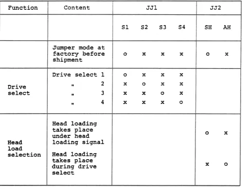
3-3 Jumper Functions
Table 3-1 shows the jumper selection for the MDD.
The way in which the jumpers are set at the factory is
indicated on the unit.
If the unit is returned for repair, etc., we will
redeliver it with the jumpers set to the initial factory
specifications.
Set the jumpers according to whether drive select is to
be performed using select '1' or ' 2 ' , and also whether
head loading is to be performed by means of a head load
Table 3-1 Jumper s e l e c t i o n t a b l e
3-4 Arrangement of Jumper P i n s
F u n c t i o n
Drive select
Head l o a d
s e l e c t i o n
SELECT 1
. SELECT 2
SELECT 3
JJ1
S 1 S2 S3 S4
0- x x x
o x x x
X 0 X X
x x o x
X X X 0
Content
Jumper mode a t f a c t o r y b e f o r e shipment
Drive select 1
!I 2
I* 3
I* 4
Head l o a d i n g t a k e s p l a c e under head l o a d i n g s i g n a l
Head l o a d i n g t a k e s p l a c e d u r i n g d r i v e select
HEL4D LOAD
J J 2
SH AH
o x
0 X
[image:19.594.81.553.85.454.2]4. Dimension Specifications 4-1 Installation Method
Install the MDD according to the method shown below. (1) Installation with PCB at top
(2) Installation with PCB at right ( 3 ) Installation with PCB at .left
5. Handling Mini F l o p p y D i s k s
T h e f o l l o w i n g a r e the p r e c a u t i o n s t o b e o b s e r v e d when h a n d l i n g mini f l o p p y d i s k s .
[ U n s a t i s f a c t o r y ] [ S a t i s f a c t o r y ]
o
50
n o t expose d i s k s t o d i r e c t s u n l i g h t o r p l a c e them n e a r a s o u r c e of h e a t . o Do n o t p l a c e d i s k si n a p l a c e which is s u b j e c t t o t h e i n f l u e n c e o f a magnetic f i e l d . a o Do n o t expose d i s k s
t o c i g a r e t t e smoke. o Do n o t p u t c l i p s o r
r u b b e r bands on d i s k s .
o S t o r e d i s k s i n a c l e a n environ- ment a t s u i t a b l e temperature and humidity
.
o When n o t u s i n g a d i s k , i n s e r t i t i n a n envelope, t h e n i n s e r t t h e envelope i n a s p e c i a l - purpose c a s e , and s t o r e i t v e r t i c a l l y .
o P a s t e l a b e l s on d i s k s a f t e r w r i t i n g on them f i r s t .
o Before u s i n g a d i s k , o Do n o t write i t i s recommended
d i r e c t l y on d i s k s t h a t i t be l e f t f o r u s i n g a pen o r a s u i t a b l e t i m e i n p e n c i l . t h e same environment
1
0
a s t h e . d r i v e i n o r d e r t o a c c l i m a t i z e o Do n o t touch t h e i t .r e c o r d i n g f a c e o f d i s k s (oblong h o l e
p o r t i o n )
.
o Completely i n s e r t t h e media t o t h e o Do n o t bend o r f o l d back of t h e d r i v ed i s k s . b e f o r e c l o s i n g t h e door.
6. Format Example
The format of the soft selector used with the MDD is shown
in the table below.
Format examples for F.M. 16-sector format and M.F.M. 16-
sector format are shown in Fig. 6-1.
C o d ~ c a to IS0
Conf-ca to m M
F M / M F M
F M
M F M
FM
M F M
Data amount/trPck 2 0 4 8 bfes
2 3 0 4 f f
2 5 6 0 f f
4 0 9 6 f f
4 6 0 8 a
5 1 2 0 f f .
1 9 2 0 f f
2 0 4 8 f f
2 0 4 8 f f
4 0 9 6 n
4 0 9 6 f f
4 0 9 6 f f
Sector forrrmt
1 6 -om
9 f f
5 ff
16 a
9 f f
5 "
1 5 n 8 " 4 f f
1 6 f f
8
*
4 a
Data aa~ount/wctor 1 2 8 b ~ t a
2 5 6 a
5 1 2 f f
2 5 6 f f
5 1 2 n 1 0 2 4 f f
1 2 8 f f
2 5 6 a 5 1 2 a
2 5 6 f f
5 1 2 f f