International Journal of Innovative Technology and Exploring Engineering (IJITEE)
ISSN: 2278-3075, Volume-8 Issue-8 June, 2019
Performance Analysis of Power line Fault not
touching the ground
Umesh Kumar Sinha
Abstract: Till now there is no protecting devices are identified Downed or Broken power line Fault not touching the ground. Identification of fault and location of fault is easy for all faults, but Downed or Broken power line Fault not touching the ground identification and location of this fault is very difficult because of these faults not enough faults current to operate fault detection devices in Over Head power distribution. The proposed solution for Fault location and finding of Downed or Broken power line Fault not touching the ground
Index Terms: Power line communication (PLC), PLG (Power Line Guardian), High Impedance Faults (HIF’s), Active Smart Wires (ASW)
I. INTRODUCTION
Power system protection is a critical issue for both operational and safety reasons. An efficient protection scheme should be adapted ensuring the power system operates adequately and protects the equipment’s as well as public from hazardous over voltages. Hence an ideal power system Protection scheme should be introduced to make sure that no hazardous over voltages will put the human life or equipment operation at risk under any circumstances Detection of high impedance faults on overhead distribution systems continues to be an unsolved problem for electric utilities. The root problem is that a high impedance fault does not cause a detectable change in current flow on a circuit. The much more common low impedance faults cause substantial fault current to flow and are easily detectable. Downed conductors are of major concern to electric utilities because they may result in public hazard. Downed conductors may not contact a conductive object and, therefore, have good probability of remaining energized. When lying on certain surfaces, they may look quite harmless. A person touching an energized power line conductor faces substantial risk, since no detection device known today can react fast enough to prevent injury. The only available solution to this problem today is an alert and informed public [1]. The issue of how to respond, once a downed conductor (HIF) is detected, is paramount. This will often determine whether the overall risk to the public has truly been minimized [2]-[6]. Different types of data transmission system can be used depending upon the network requirement and conditions. New PLC communication system are created and used in Smart Grid [7] to read smart meter Data, Communication systems and House automation system using Power line communication system [8]. Power line communication is mainly used for Detection of High Impedance Fault Occurrence’s [9].
Revised Manuscript Received on June 05, 2019
Dr. Umesh Kumar Sinha, Associate Professor in Electrical Engineering department, National institute of Technology, Jamshedpur (India)
Smart grid and secure smart grid are being used today to describe technologies that automatically and rapidly isolate faults, restore power, monitor demand, and maintain and restore stability for more reliable generation, transmission, and delivery of electric power [10]-[11]. Smart grid Provide solution for the fault or event and provides electricity free of sags, spikes, disturbances and interruptions. Active Smart Wires (ASW) is a new concept for a low-cost, high reliability method to increase or decrease power flow in a transmission line and as well as observe power line between pole to pole every time with [12]-[14]. Transmission line Faults and fault location finding is very important for power system. As compare to impedance method, travelling wave method would give accurate results [18]-[23]. The drawback of this method is depending upon system parameters and configuration of network [24]-[25]. Travelling waves measured by using Current transformers [26]-[27].
This paper discusses about Design and Working of F-PLCCG (Frequency Power Line Carrier Communication Guardian) (Sec 2), F-PLCCG working in field Flow chart and Algorithms (Sec. 3), Simulation Results of F-PLCCG (Sec .4), Hybrid AD Method (Sec .5), Simulation Results of Hybrid AD Method (Sec .6) and Conclusion (Sec.7).
II. DESIGN, WORKING PRINCIPLEAND
OPERATION OF F-PLCCG
(Frequency Power Line Carrier -Communication Guardian): The proposed Design of F-PLCCG is used for Detection of unbroken/broken conductor hanging within inches from the ground fault or downed power line conductors fault between two sub-Stations and within village, (explained in Flow Chart 1 and flow chart 2), the design and operation of F-PLCCG is explained in below.
1. DESIGN OF F-PLLCCG (COMPONENTS)
The F-PLCC Contains Components like Transformer (T1), Transformer (T2), Switches S1, S2, S3, Power supply, Program Logic controller (S7-1200) with GSM connection, Communication system, FSK Demodulator, Micro controller for data recovery, Digital data converter, SCR(Silicon controller Rectifier) Circuit (ST1,ST2) and Coupling Circuit capacitor (Figure.1) and components working explained below (Figure.1)
1. Transformer (T1) of Primary act as a Power conductor. 2. Transformer (T1) of Secondary act as a Primary of T2 3. If Switch S4 closed, Combination of Switch S4 and
SCR’s ST1&ST2 act as a Power line guardian Circuit. 4. Coupling capacitor for allowing high frequency signals
to F-PLCCG
5. S7-1200 (contains pre- program) and Communication system will receive power supply from Transformer (T1).
decreasing carrier signal frequency received from T2 secondary.
7. Communication system having GSM modem for sending data to Sub stations or rural transformer switch board
Figure1. F-PLCCG Schematic Circuit
2. WORKING PRINCIPLE AND OPERATION OF
F-PLCCG:
F-PLCCG is following basic principle of Power Line communication system. Please follow below Steps how it will detect downed power line conductors’ fault between two sub stations.
Step 1: Once Program Logic Controller signal received from Substation “A”, Switches S1, S2 & S3 will closed by using Program Logic Controller (at F-PLCCG).
Step 2: Coupling Circuit Capacitor will allow high Frequency Signal, Step down Transformer T2 Step-down Voltage signal. Step 3: Step-downed voltage signal send to FSK Demodulator, it will Demodulated Frequency to Low frequency signal.
Step 4: MC (Micro – Controller) Correct the Error in Low Modulated Frequency Signal.
Step 5: Frequency convert into Digital signal and send digital value to Programmable logic controller.
Step 6: Program logic controller will check Frequency value and send signal to Communication system “OK” or “NOK” (pre-program logic written in Ladder logic, explained below).
Step 7: Depends upon Signal Received from Communication system in F-PLCCG, send signal to substations for switch off power supply between two sub stations or Switch off power supply to rural area.
Programmable logic: Program Logic Controller Logic for Operation of switches in F-PLCCG. From program logic going to switch on/off switches “S1”, S2”,” S3” and “S4” by using power off signal input and PLG input signal. (Please find Logic of operation in below diagram Fig.2).(Find supplementary Document).
Figure2. Operation of switches in Programmable Logic Controller
Please follow below steps to make switch’s enable by Program logic explained in (Figure 2)
Step 1.To make Memory bit %M0.0 (Tag_1) ON with help of (PLC from substation is) %M23.0 should ON, (power off signal) %I0.7 should OFF.
Step 2. To make on-delay timer (#input_1 (preset time=5milli seconds)) on using (Power off signal) %I0.7 must off, Tag_1 (%M0.0) must ON.
Step 4Tto make Switch S4 ON with help of Power
Step 3.Once timer on All S1 (%Q0.2), S2 (%Q0.1) and S3 (%Q0.0) be ON. off signal(%I0.7) should OFF and PLG Input(%I0.6) should ON.
III. DETECTION OF UNBROKEN BROKEN
CONDUCTOR HANGING WITHIN INCHES OF THE GROUND FAULT OR DOWNED
POWER LINE CONDUCTORS FAULT USING F-PLCCG FIELD OPERATION AND
ALGORITHMS.
According to literature survey one major problem has identified.
1. Problem is Downed conductors which are not touching the ground has become major concern to electric utilities because this fault cannot be measured by the fault detecting devices. This may result in public harm. 2. Downed conductors may not contact a conductive
object, therefore is more probability of remaining energized.
3. When lying on certain surfaces, they may look quite harmless. When any person touches an energized power line conductor, faces substantial risk, since no detection device known today can react fast enough to prevent injury.
4. In recent years observed that many cases were registered in so many countries like India, USA, Germany, etc. The only available solution to this problem today is to give an alert and inform public. To solve above problem Companies like Siemens, GE, ABB, etc. have a solution, but that solution has only 90% success rate [15]-[17].
5. To solve above problem proposing new enhanced model circuit. It contains F-PLCCG, Program logic controller (Siemens PLC CPU -1200) for logic function operated in F-PLCCG. The Proposed solution unique approach towards solving problem compared to other proposed solutions.
The proposed solution explains how to deal with unbroken/broken conductor hanging within inches of the ground fault or downed power line conductors’ fault. Here Explaining how to use proposed solution in between two sub-Stations and as well as with in Rural village.
Proposed solution solves Fault Detection between Substation to substation is explained in
Ø Flow chart 1 (Figure.3) using some Preconditions. Ø Algorithm Steps (F-PLCCG working in field) Ø Field connection diagram
International Journal of Innovative Technology and Exploring Engineering (IJITEE)
ISSN: 2278-3075, Volume-8 Issue-8 June, 2019
between Substations to Rural village explained in Ø Flow chart 1 (Figure.5) using some Preconditions, Ø Algorithm Steps (F-PLCCG working in field) Ø Field connection diagram of F-PLCCG (Figure.6)
Flow Chart 1: F-PLCCG operation between substations to substation is explained below flow chart.
Figure3.Flow Chart: F-PLCCG operation between substations to substation
Figure4. F-PLCCG Field Connection between substations to substation
PRECONDITION:
Step 1: At equal distance between Sub-Station “A” &”B”, arrange F-PLCCG
Step 2: F-PLCCG (Frequency Power Line Carrier Communication Guardian) has Frequency Receiver in Bi-Directional mode.
Step 3: Preferred frequency for PLC (Power Line carrier) is 100 KHZ to 140 kHz
Step 4: Sub-Station “A” &”B” contains PLC Modem and program Logic controller (Pre-program) unit with GSM connection.
Step 5: For Better understanding of Algorithms, we symbolize Power line communication signal as Communication signal and Program Logic Controller Signal as Automation signal. Algorithms Steps (Figure.3):
Step 1:Sub-station “A” PLC Modem will send “communication Signal” to “F-PLCCG“ via Transmission line and as soon as signal passes from PLC modem, Program Logic Controller(at substation) sends “Automation signal’ to Program Logic Controller(at F-PLCCG) for activation of Switches
(Figure.2).
Step 2: Once the Communication signal signals reached “F-PLCCG”, Status of the Transmission line is sent to Two Sub-Stations via Communication system arranged in “F-PLCCG”.
Step 3: F-PLCCG sends only “OK” or “NOK” Signal to Two Sub stations. If F-PLCCG signal status is “OK” it will execute as in Step 4, if “NOK” then it will execute as in Step 6&7
Step 4: Stop Communication signal from Substation “A” and from substation “B” send Communication signal to “F-PLCCG” and when signal passes from PLC modem, Program Logic Controller sends automation signal to F-PLCCG for activation of Switches (Figure.2).
Step5: Once Communication signal reaches “F-PLCCG”, Status of Transmission line send to Two Sub-Stations via Communication system arranged in “PLCCG” and F-PLCCG send only “OK” or “NOK” Signal to Two Sub stations. If FC PLCCG status is “OK” it will execute as in Step 1, if it’s “NOK”, it will execute as in Step 6&7 Step 6: Communication signal not reached “F-PLCCG “, It will Generate “NOK” Signal i.e. Transmission line broken and sent this Automation signal to Sub stations “A” &”B” and Generates Alarm for Disconnect Power supply from Both “A” &”B” Substation or automatic Disconnection of Power supply By SCADA System in Both “A” &”B” Substation.
Step 7: Once the line repair is executed, then Operator must press Ready button then controller start power supply to village and it will execute as in step 1.
Flow Chart 2: F-PLCCG operation between substations to Village is explained below flow chart.
Figure5.Flow Chart: F-PLCCG operation between substations to Village
PRECONDITION FOR FLOW CHART 2:
Step 1: F-PLCCG connected at every power distribution node for streets.
Step 2: Connect PLC Device at Transformer (in rural area) and Transformer power connection Switch on/Switch off operation using by Pre-Programmable logic controller (Control Box).
Step 3: Each street end at the last electric transmission pole is connected to PLC Device and Village T/F (Transformer) having PLC Modem and when Communication signal passes from PLC modem of T/F, Program Logic Controller (located at street end last electric transmission pole) it sends Automation signal to Program Logic Controller (at F-PLCCG) for activation of Switches (Figure.2).
Step 4: Preferred frequency for PLC (Power Line carrier) is 100 KHZ to 140 kHz
Step 5: In village/rural area each Home contains Smart Meter and each smart meter contains Wave Trap unit.
Step 6: For Better understanding of Algorithms, we symbolize Power line communication signal as Communication signal and Program Logic Controller Signal as Automation signal. Algorithms Steps:
Step 1: T/F PLC Modem will send communication Signal “X” to F-PLCCG via Transmission line
Step 2: F-PLCCG receives “X” signal and status of Transmission line send to Sub-Station “A” & Control Box at T/F (Transformer) via Communication system arranged in “F-PLCCG”. F-PLCCG sends only “OK” or “NOK” Signal to Sub stations. If F-PLCCG status is “OK” it will execute as in Step 3, if it’s “NOK”, it will execute as in Step 5. Step 3: Stop “X” Signal from Transformer PLC. F- PLCCG Receives Communication signal “Y” from Street 1 of PLC Modem and Status of Transmission line send to Sub-Station “A” & Control Box at T/F (Transformer) via Communication system arranged in “PLCCG” and F-PLCCG sends only “OK” or “NOK” Signal to Sub stations. If F-PLCCG status is “OK” it will execute as in Step 4, if it’s “NOK”, it will execute as in Step 5.
Step 4: Stop “Y” Signal from Street 1.F-PLCCG Receives Communication signal “Z” from Street 2 of PLC Modem and Status of Transmission line send to Sub-Station “A” & Control Box at T/F (Transformer) via Communication system arranged in “FT PLCCG” and F-PLCCG sends only “OK” or “NOK” Signal to Sub stations. If F-PLCCG status is “OK”, it will execute as in Step 5, if it’s “NOK”, it will execute as in Step 5
Step 5: If F-PLCCG generated “NOK” Signal and send Automation Signal to within rural village Transformer and substation. Transformer control box having Program Logic controller loaded with Preprogram with all these conditions, once received “NOK” signal from F-PLCCG controller will disconnect power supply to Village. Once line repair executed then Operator has to press Ready button in control box, after controller start power supply to village and it will execute as in Step 1.
IV. SIMULATION RESULTS OF F-PLCCG
We used MATLAB for this simulation results. Inputs for Simulation Results: From Substation “A”: Power line communication with frequency 1 kHz, Normal powers supply 440v AC, 50Hz.Output measured across Secondary of T2.Figure 7. Secondary of T2 Transformer Output FrequencyAs per Simulation results (Figure.7.) at 0.04 sec output frequency of T2 Transformer is input for FSK, FSK output is input for Frequency to Digital conversion, Digital conversion frequency is equal to output signal frequency at F-PLCCG.it indicates down conductor fault not occurred. If both frequencies not equal it’s indicated down conductor
fault occurred.
V. HYBRID AD METHOD:
In above sections explained about travelling wave method for finding open-circuit location, Power line guardian (PLG) for power flow control, Harmonics in Power system (2nd harmonic). Using Travelling wave method, Power line guardian and 2nd harmonic, we are going to propose new method to find Location of Downed or Broken power line Fault not touching the ground. The proposed method is very simple, and less cost and it will give exact location. In this method PLG (Power line guardian) would play big role and using 2nd harmonic travelling wave, we are going to find Location of Downed or Broken power line Fault not touching the ground. PLG having Current transformer and it will measure High frequency ranges (Travelling wave frequency). To find distance of fault please follow below Operation of Hybrid AD Method .Operation of Hybrid AD method: Please follow below Steps how to detect Location of downed power line conductors’ fault between two sub stations. Precondition: 1. First calculate Distance between two sub-stations (distance D)2.PLG connected between equal distance (at Pont P) (Figure.8) from two sub-stations A and B. Please follow below cases how Hybrid AD method help to detect location of fault.
Case 1: Fault occurred between Station A and PLG Step 1: When Downed or Broken power line Fault not touching the ground occurred (at Point F) (Figure.9) at that point 2nd harmonic first travelling wave generated and travelled towards Station A and Station B.
Step 2: measure 2nd harmonic first forward travelling wave timing between fault point “F” to PLG Point “P”.
Step 3: measure 2nd harmonic first forward travelling wave from fault point “F” to Station B.
Step 4: measure first reflected travelling wave from station B to fault point (at point F).
International Journal of Innovative Technology and Exploring Engineering (IJITEE)
ISSN: 2278-3075, Volume-8 Issue-8 June, 2019
P.D= Total distance between station A and Station B[m];DX= Fault location distance from Station B[m]F= Fault point location, P= Power Line Guardian arranged on transmission line, TL=First forward travelling wave time between Fault point (F) and PLG point (P) [s]
TPB = First forward travelling wave time between PLG point (P) and Station B[s]; TR-PB = First reflected travelling wave time between PLG point (P) and Station B[s]T = First forward travelling wave time between Fault point (F) and Station B[s];PLG= Power Line Guardian, V = wave velocity =Total travelling time [s] + )/10 ……… (1)
Fault location distance from Station B DX=. ……….(2)
CASE 2: FAULT OCCURRED BETWEEN STATION BAND PLG:
Step 1: When Downed or Broken power line Fault not touching the ground occurred (at Point F) (Figure.10) at that point 2nd harmonic first travelling wave generated and travelled towards Station A and Station B (Figure.10).
Step 2: measure 2nd harmonic first forward travelling wave timing between fault point “F” to PLG Point “P”
Step 3: measure 2nd harmonic first forward travelling wave from fault point “F” to Station A
Step 4: measure first reflected travelling wave from station A to fault point (at point F)
Step 5: measure first reflected travelling wave from station A to at Point PD= Total distance between station A and Station B[m];DX= Fault location distance from Station B[m]F= Fault point location; P= Power Line Guardian arranged on transmission line; T L=First forward travelling wave time between Fault point (F) and PLG point (P) [s]TPA = First forward travelling wave time between PLG point (P) and Station A [s];TR-PA = First reflected Travelling wave time between PLG point (P) and Station A[s]T1 = First forward travelling wave time between Fault point (F) and Station A[s];PLG= Power Line Guardian, V = wave velocity =Total travelling time [s] + )/10…………. (3) Fault location distance from Station A, DX=. ……… (4)
6. SIMULATION RESULTS OF HYBRID AD METHOD
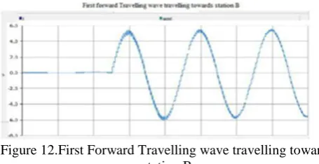
[image:5.595.49.277.627.744.2]We used PSCAD V4.2 for this simulation results. if we apply in Theoretical calculation to simulation for Case 1, Distance between station A and B is 100 Kilo meters. If Downed or Broken power line Fault not touching the ground occurred at 25 Km from Station A.
Figure 12.First Forward Travelling wave travelling towards station B
The 2nd harmonic generated at fault point and fault travelling wave travelling towards station B From Simulation Results, = 0.188, = 0.376, = 0.6837
Location. +
The proposed solution provid)/10 , Fault location distance from Station B D X=
7. CONCLUSION
es almost 100% accurate solution for Detect and location of Downed power lines Fault without touching ground. As compare to all of that’s methods and process, the proposed solution will give better Solution, economic and within less time. This Paper provides solution used for rural area/village and between two substations for fault detection and location between two sub stations.
Acknowledgment : We would like to thank Siemens AG ,Germany & Siemens Technology and Services Pvt Ltd,India sponsored for my research work & National institute of Technology ,Jamshedpur supported my research work.
REFERENCES
1. IEEE Power and Energy Society, “Downed Power Lines: Why They Can’t Always Be Detected,” Technical Report PES-TR2, formerly TPPESDPL3, February 1989.
2. “Detection of Downed Conductors on Utility Distribution Systems”,
IEEE PES Tutorial Course, 90EH0310-3-PWR, Piscataway, NJ: IEEE, 1989.
3. “Catching Falling Conductors in Midair – Detecting and Tripping Broken Distribution Circuit Conductors at Protection Speeds”, 42nd Annual Western Protective Relay Conference Spokane, Washington, October 20–22, 2015
4. B. Cook and K.Garg, “Designing a Special Protection System to Mitigate High Interconnection Loading Under Extreme Conditions – A Scalable Approach,” proceedings of the 40th Annual Western Protective Relay Conference, Spokane, WA, October 2013.
5. D.Hou, “Detection of High-Impedance Faults in Power Distribution
Systems,” proceedings of the 33rd Annual Western Protective Relay Conference, Spokane, WA, October 2006.
6. D. Hou and N. Fischer, “Deterministic High-Impedance Fault
Detection and Phase Selection on Ungrounded Distribution Systems,” proceedings of the 32nd Annual Western Protective Relay Conference, Spokane, WA, October 2005.
7. “For the Grid and Through the Grid: The Role of Power Line Communications in the Smart Grid” ,Stefano Galli, Senior Member, IEEE, Anna Scaglione, Fellow, IEEE, Zhifang Wang, Member, IEEE, Submitted May 28, 2010. Revised Sep. 12, 2010, and Jan. 12, 2011
8. Cataliotti, A., &Tinè, G. (2009). “On the model of MV power line communication system in the case of line to line transmission”. Proceedings of XIX IMEKO World Congress Fundamental and Applied Metrology. Lisbon, Portugal.
9. “Automatic Meter Reading for Electricity using power line
communication”,PoonamBorle, AnkitaSaswadkar, DeepaliHiwarkar, Rupali S. Kad, International Journal of Advanced Research in Electrical, Electronics and Instrumentation Engineering Vol. 2, Issue
3, March 2013
10. “Power line Communication Based on Energy Meter Automation”,
Namita N. Jinde, Rashmi K. Bhojane,Reetesh V. Golhar, International Journal of Electronics Communication and Computer Engineering Volume 4, Issue (2) REACT-2013, ISSN 2249–071X
11. “Smart Meters Reading Through Power Line Communications”,MirceaPopa ,Journal of Next Generation Information Technology. Volume 2, Number 3, August 2011
12. “Enhanced Protection Scheme for Smart Grids Using Power Line Communications Techniques—Part I:Detection of High Impedance Fault Occurrence”, Apostolos N. Milioudis, Georgios T. Andreou, and Dimitrios P. Labridis, IEEE TRANSACTIONS ON SMART GRID, VOL. 3, NO. 4, DECEMBER 2012
13. “Active Smart Wires: An Inverter-less Static Series Compensator”, Frank Kreikebaum and MunuswamyImayavaramban, 2010 IEEE
14. “Smart Wires – A Distributed, Low-Cost Solution for Controlling Power Flows and Monitoring Transmission Lines”,FrankKreikebaum, Debrup Das, Yi Yang, Member,Frank Lambert and Prof. Deepak Divan
15. http://w3.siemens.com/smartgrid/global/en/products-systems-
impedance-protection/pages/overview.aspx [16] www.library.e.abb.com 16. www. store.gedigitalenergy.com
17. Röhrig, “Location of faulty places by measuring with cathode ray
oscillographs”, ElektrotechZeits, 8, 241-242 (1931)
18. “Traveling wave fault location in power transmission systems:An Overview”, G. Krzysztof ,R. Kowalik ,D. Rasolomampionona ,S. Anwar, J. Electrical Systems 7-3 (2011): 287-296.
19. “Detecting the fault location using Traveling wave”,IoanBarburas,Tadormihaipetrovan,IchimNasui,StelianBugnar,I oanaNasuiZah,Ioan Boiciuc,6th International Conference on Moderan Power systems MP2015,18-21 May 2105,CLUJ-NAPOCA,Romania.
20. “Traveling Wave Fault Location in Power Transmission Systems”,
Application Note 1285, Hewlett Packard
21. “Fault location using Travelling waves “,Peterhossley and Magnus
Davidson ,Phil Gale, 1993 The Institution of Electrical Engineers . [23] “On travelling-wave-based protection of high-voltage networks”,Bollen, M.H.J,Technischeuniversiteit Eindhoven.
22. M. H. Idris, Member, IEEE, M. W. Mustafa, Member, IEEE and Y. Yatim, “Effective Two-Terminal Single Line to Ground Fault Location Algorithm”, June 2012
23. T. Kawady and J. Stenzel. “Investigation of practical problems for
digital fault location algorithms based on EMTP simulation”, Asia[ Pacific Transmission and Distribution Conference and Exhibition, 2002, Vol. 1, pp.118-123
24. “Fault location using the high frequency travelling waves measured at a single location on a transmission line”,M Aurangzeb, P.A. Crossley and P. Gale, Developments in Power System Protection, Conference Publication No.479 0 IEE 2001
25. “The Application of Distribution System Current Transformers for High Frequency Transient Based Protection”,M A Redfem, S C Terry, F V P Robinson, and Z Q Bo, T h e Institution of Electrical Engineers, 2004.
AUTHOR’S PROFILE
Dr. UMESH KUMAR SINHA is Associate Professor in Electrical Engineering department, National institute of Technology, Jamshedpur (India) has got B. Sc. Engineering f MIT. M. Tech. (Power Electronics) from Ranchi University and Ph. D. (Simulation and Modelling of Solar Pons for Power Generation). The area of research is Solar and Renewable Energy Systems. There are more than twenty eight publications at International level.Payment Details
Annual Processing Charge
₹ 8000/-
Give Us Following Details
Your Name * UMESH KUMAR SINHA
Your Address * Department of Electrical Engineering, N. I. T. Jamshedpur-831014
Your Email * [email protected] Your Phone * 9931112196
Paper ID * H6663068819