Int. J. Electrochem. Sci., 7 (2012) 2214 - 2220
International Journal of
ELECTROCHEMICAL
SCIENCE
www.electrochemsci.orgPreparation and Electrochemical Properties of Hollow Nickel
Oxide Fibers
Liu Junqing1,2, Shi Jingli1,*,Yan Xi1, Zhai Xiaoling1,2, Tao Zechao1, Guo Quangui1, Liu Lang1 1
Key Laboratory of Carbon Materials, Institute of Coal Chemistry, Chinese academy of Sciences, Taiyuan 030001, China.
2
Graduate University of the Chinese Academy of Sciences, Beijing 100039, China *
Corresponding author. Tel.: +86 3514083952; Fax: +86 3514083952; E-mail address: *
E-mail: shijingli1963@163.com
Received: 8 January 2012 / Accepted: 14 February 2012 / Published: 1 March 2012
In order to make better use of nano-nickel oxide particles, hollow nickel oxide fibers (HNOFs) were prepared by electroplating nickel particles on the surface of mesophase pitch based carbon fibers (MPCFs) and then burned off the carbon fibers under air atmosphere. Scanning electron microscopy showed that the HNOFs had hollow holes in center with diameter about 10 µm and the HNOFs fiber wall were made up of nickle oxide nanoparticles whose sizes ranged from 10 to 500 nm. The thickness of HNOF fiber wall can be controlled from tenths of micrometer to tens of micrometer. Thermogravimetric analysis and X-ray diffraction indicated that the nickel coated on MPCF surface was oxidized to nickel oxide when the heat treatment temperature was higher than 400 ℃ and the MPCF substrate decomposed when the temperature was higher than 600 ℃. Moreover, the nickel oxide had a high crystallinity when the heat treatment temperature was higher than 700 ℃. To be used as electrode for supercapacitor, the HNOFs showed well electrochemical properties. The specific capacitance of HNOFs with 0.8 μm fiber wall was 480 F/g with the current of 50 mA/g.
Keywords: Nanoparticles; Nickel oxide; Hollow fiber; Electrochemical properties
1. INTRODUCTION
can be electroplated onto MPCF surface easily. Therefore, nickel oxide nanoparticles could be facilely prepared by electroplating method. The particle size and the thickness of coating could be controlled by the electroplating current density and time.
In this paper, HNOFs were successfully prepared by electroplating nickel particles on the surface of MPCFs. The structure of carbon fibers was too dense, therefore, there was not enough pores in carbon fibers to store electric charge. In order to enhance the specific capacitance, the carbon fiber substrate was burn off under air atmosphere. The generation process, structure and specific capacitance of HNOFs were studied.
2. EXPERIMENTAL 2.1. Preparation of MPCFs
Naphthalene-based AR mesophase pitch produced by the Mitsubishi Gas-Chemical Company was used. The mesophase pitch was melt-spun at 320 ℃ and extruded through a spinneret under the press of nitrogen gas. The as-spun fibers were oxidatively stabilized in air at 260 ℃ and then carbonized in pure N2 gas at 1000 ℃. The MPCFs prepared have average diameter about 10 µm and electrical resistivity about 19 µΩ·m (The main properties of MPCFs are similar to Thornel-P25).
2.2. Preparation of HNOFs
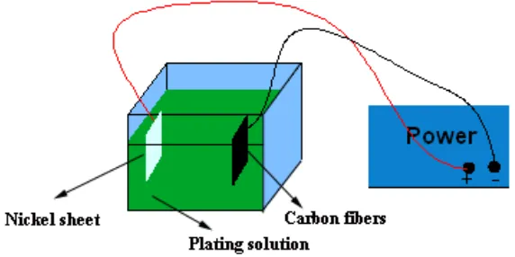
Figure 1. The sketch map of plating process
2.3. Characterization of HNOFs
The surface patterns of HNOFs were characterized by S-4800 field emission scanning electron microscopy (SEM, Hitachi, Japan). The components of hollow fibers were analyzed by X-Ray diffraction (XRD, D8 Advace, Germany) using copper Kα X-rays (λ = 0.1541 nm). Thermogravimetric (TG) analysis and differential thermogravimetry (DTG) were carried out on a STA 409PC (Netzsch, Germany). The thermograms were acquired between 30 and 900 ℃ at a heating rate of 5 ℃/min. Nitrogen and air were used as the gas at a flow rate of 10 and 60 mL/min respectively.
2.4. Electrochemical measurement
Electrodes were prepared by mixing the active materials with 10 wt% acetylene black and 10 wt% polytetrafluoroethylene (PTFE) of the total electrode mass. A small amount of alcohol was then added to this composite to make more homogeneous mixture, which was pressed on nickel foam to fabricate the electrodes. Electrochemical characteristics of the HNOFs were determined by galvanostatic charge and discharge method and cyclic voltammetry method in a three-electrode cell with 6 M KOH electrolyte, a platinum foil was used as the counter electrode and a saturated Hg/HgO electrode as the reference electrode.
3. RESULTS AND DISCUSSION 3.1. TG analysis of nickel coated MPCFs
Figure 2. TGA-DTG curve of nickel-coated MPCFs
3.2. Generation process of nickel oxide
[image:4.596.138.462.513.725.2]
Fig. 3 shows the XRD patterns of nickel-coated MPCFs burned in air at 300, 500, 700 and 900
℃. Analysis of the diffraction patterns reveals that nickel-coated MPCFs heat treated at 300 ℃ consist of two sets of peaks, which are corresponding to carbon and Ni respectively. A new diffraction peak belonged to NiO appears after a heat treatment at 500 ℃. It shows that the Ni coated on MPCF substrate has been oxidized to NiO when the sample was heat treated at 500 ℃. The diffraction peaks of carbon and Ni become weaker as the treatment temperature increases. When the treatment temperature was higher than 700 ℃, the diffraction peaks of carbon and Ni had disappeared. It shows that the carbon fibers have burn off and the Ni has oxidized into NiO under 700 ℃. Moreover, the characteristic peaks of NiO heat treated at 700 and 900 ℃ are narrower than that heat treated at 500
℃. This indicates a high crystallinity of NiO heat treated at higher temperature than 500 ℃. The average particle size can be calculated using Scherrer formula [15], the average particle size of samples heat-treated at 700 and 900 ℃ are 41 and 83 nm respectively. It shows that the size of NiO particles grows with the heat treatment temperature increasing. So, the NiO particle size and crystallinity can be controlled by the heat treatment temperature.
3.3. Surface patterns of MPCF and HNOFs
Figure 4. SEM image of MPCF (a), SEM image along HNOF-10 axis (b), cross-section texture of HNOF-10 (c) and HNOF-1 (d)
[image:5.596.115.484.362.638.2]3.4. Electrochemical properties of HNOFs
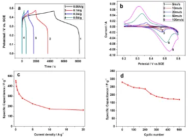
Figure 5. Charging and discharging curve of HNOF-1 (a), cyclic voltammetry curves of HNOF-1 (b) and specific capacitance curve of HNOF-1 (c), cycle test of specific capacitance of HNOF-1 at 2A/g (d)
The specific capacitance was calculated by the following equation:
/ C i t m v
[image:6.596.106.475.254.529.2]
charge-discharge current density. The diffusion resistance of electrolyte increases with the current density increasing. This is the main reason for the deamplification of specific capacitance. Fig. 5d shows that the specific capacitance of HNOF-1 decreased about 30 % after 500 cycles. The swell and shrink of NiO in electrolyte will cause the decrease of specific capacitance. Additional, the stability of specific capacitance of HNOFs during 100 to 200 cycles might related to the formation of Ni(OH)2 on the surface of the NiO electrode. It has been shown that the specific capacitance of NiO electrode will increase due to the formation of Ni(OH)2 in many researches [12,16,17].
The surface area of HNOF-1 in this study is 56 m2/g according to BET test. The high surface of HNOFs leads to high specific capacitance of HNOF electrode.
4. CONCLUSIONS
HNOFs were successfully prepared by electroplating nickel particles on the surface of MPCFs and then burned off the MPCFs. The obtained HNOFs are made up of nano-sized nickel oxide particles and the size of nickel oxide particle grows with the heat treatment temperature increasing. Moreover, electroplating process is controllable that the thickness of HNOF fiber wall could be tuned easily by adjusting the electroplating current density and time. The HNOFs have high specific surface area which make HNOFs show well electrochemical properties when it was used as electrode of capacitor.
References
1. Z. Gu, K. Hohn, Ind. Eng. Chem. Res., 43 (2004) 30
2. F.B. Zhang, Y.K. Zhou, H.L. Li, Mater. Chem. Phys., 83 (2004) 260 3. Y.I. Yoon, J.M. Ko, Int. J. Electrochem. Sci., 3 (2008) 1340 4. Q. Yang, J. Sha, X.Y. Ma, D.R. Yang, Mater. Lett., 59 (2005) 1967
5. Q. Li, L.S. Wang, B.Y. Hu, C. Yang, L. Zhou, L. Zhang, Mater. Lett., 61 (2007) 1615 6. X.Y. Deng, Z. Chen, Mater. Lett., 58 (2004) 276
7. Z. Fan, J.H. Chen, K. Cui, F. Sun, Y. Xu, Y.F. Kuang, Electrochim. Acta., 52 (2007) 2959
8. A.S. Adekunle, K.I. Ozoemena, B.B. Mamba, B.O. Agboola, O.S. Oluwatobi, Int. J. Electrochem. Sci., 6 (2011) 4760
9. S.L. Che, K. Takada, K. Takashima, O. Sakurai, K. Shinozaki, N. Mizutani, J. Mater. Sci., 34 (1999) 1313
10.D.J. Kang, K.N. Kim, S.G. Kim, K. Dong, K. Ku, J. Mater. Sci., 40 (2005) 6283
11.Y.N. Hu, V. Yuriy, Tolmachev, A. Daniel, Scherson, J. Electroanal. Chem., 468 (1999) 64 12.K.W. Nam, E.S. Lee, J.H. Kim, Y.H. Lee, K.B. Kim, J. Electrochem. Soc., 152 (2005) A2123 13.M.S. Wu, Y.A. Huang, J.J. Jow, W.D. Yang, C.Y. Hsieh, H.M. Tsai, Int. J. Hydrogen. Energy, 33
(2008) 2921
14.H.P. Feng, T. Paudel, B. Yu, S. Chen, Z.F. Ren, G. Chen, Adv. Mater., 23 (2011) 2454 15.S.A. Makhlouf, M.A. Kassem, M.A. Abdel-Rahim, J. Mater. Sci., 44 (2009) 3438 16.P.A. Nelson, J.R. Owen, J. Electrochem. Soc., 150 (2003) A1313
17.J.Y. Lee, K. Liang, K.H. An, Y.H. Lee, Synth. Met., 150 (2005) 153