Rochester Institute of Technology
RIT Scholar Works
Theses
Thesis/Dissertation Collections
1990
Exploiting implicit parallelism in SPARC
instruction execution
Todd Michael Austin
Follow this and additional works at:
http://scholarworks.rit.edu/theses
This Thesis is brought to you for free and open access by the Thesis/Dissertation Collections at RIT Scholar Works. It has been accepted for inclusion
in Theses by an authorized administrator of RIT Scholar Works. For more information, please contact
.
Recommended Citation
Copyright
Todd Michael Austin 1990
ABSTRACT
One
way to
increase
the
performance of
aprocessing
unitis
to
exploitimplicit
parallelism.
Exploiting
this
parallelism
requires a processor
to
dynamically
select
instructions
in
a serial
instruction
stream
which can
be
executedin
parallel.As
operations are computed
concurrently,
an execution
speedup
will occur.
This
thesis
studies
how
effectively
implicit
parallelism could
be
exploitedin
the
Scalable Pro
cessor
Architecture
(SPARC)[9],
a
reduced
instruction
set
architecturedeveloped
by
Sun Microsystems.
First
ananalysis
ofSPARC
instruction
traces
will
determine
the
optimal
speedup
that
would
be
realized
by
a processor withinfinite
resources.Next,
an
analytical model of
aparallelizing
processor will
be
developed
and usedto
predict
the
effects
of
limited
resources
on
optimal
speedup.Lastly,
a
SPARC
simulator
will
be
employed
to
determine
the
actualspeedup
of resourcelimited
CONTENTS
ABSTRACT
ii
LIST
OF
TABLES
v
LIST OF
FIGURES
vi
ACKNOWLEDGEMENTS
vii
CHAPTERS
1.
INTRODUCTION
AND
BACKGROUND
1
1.1
Problem Statement
1
1.2
Previous Work
2
1.3
Theoretical
and
Conceptual
Development
3
1.3.1
Implicit
Parallelism
in Instruction Traces
3
1.3.2
The Effective Scope
of
Implicit Parallelism
6
1.3.3
The Effects
of
Compiler
Technology
on
the
Extent
of
Im
plicit
Parallelism
7
1.3.4
Instruction Issue Logic
8
1.3.5
The
Dispatch
Stack
10
1.3.6
The
SPARC
Architecture
10
1.3.6.1
The
SPARC
Instruction Set
11
1.3.6.2
The
SPARC
Register
Set
14
1.3.7
SPARC
Characteristics That Limit Run Lengths
15
2.
RESEARCH DESCRIPTION
16
2.1
Capturing
SPARC
Instruction Traces
16
2.1.1
Limitations
of
SPAR
CTrace
16
2.1.2
Instruction Trace Format
17
2.1.3
SPARCTrace Internals
19
2.2
Selecting
Programs
To Trace
20
2.2.1
The Test Set
21
2.3
Analysis
of
SPARC
Instruction Traces
22
2.3.1
Speedup
withUnlimited Resources
22
2.3.1.1
The Effects
of
Compiler
Technology
32
2.3.1.2
The
Effects
of
Compiler
Optimization
33
2.3.3
Empirical
Analysis
of
Speedup
with
Limited
Resources
. .40
2.3.4
Accuracy
of
the
Analytical
Model
48
2.3.5
Memory
Bandwidth Requirements
50
2.4
Conclusions
52
APPENDICES
A. SPARCTRACE
USERS
MANUAL
54
B. ALGORITHMS USED
56
B.l
Algorithms Used
for
Optimal
Speedup
Analysis
56
B.2
Algorithms Used
for
Resource Limited
Speedup
Analysis
57
REFERENCES
59
LIST
OF TABLES
1.1
The
SPARC Instruction
Set
12
1.2
Functional Units Used
in
the
SPARC Processor
13
2.1
Illegal
Opcode Formats
Used
for
Inserting
Information in Traces
....18
2.2
Speedup
Gained
by
the
Addition
of
the
Code
Segment Cache
20
2.3
The
SPARC Instruction
Trace Test
Set
22
2.4
Functional
Unit
Computation
Times
24
2.5
Speedup
without
Resource Limitations
25
2.6
Uncompressed
and
Compressed
Run Lengths
27
2.7
Integer ALU
Units
Required
per
Cycle
28
2.8
Floating
Point
ALU
Units Required
per
Cycle
29
2.9
Floating
Point Multipliers Required
perCycle
30
2.10
Floating
Point Dividers Required
per
Cycle
30
2.11
Floating
Point
Square
Roots
per
Cycle
31
2.12
Speedup
vs.
Compiler
Technology
32
2.13
Speedup
vs.
Compiler Optimization
34
2.14
Speedup
Results
for
the
Minimum
Configuration
44
2.15 Resource Utilization for
the
Minimum Configuration
45
2.16 Analysis Results
for
the
Medium Configuration
46
2.17 Resource Utilization
for
the
Medium Configuration
47
2.18
Analysis
Results
for
the
Maximum Configuration
48
LIST
OF
FIGURES
1.1
Taking
Advantage
of
Implicit Parallelism
in Instruction Traces
4
2.1
SPARCTrace Operation
17
2.2
Compression
by
Run Length
28
2.3
Derivation
of
Expected Run Length
with
Limited Resources
35
2.4
Effect
of
Limited Instruction
Window
Size
on
Expected Run Length
. .37
2.5
Effect
of
Limited
Functional Unit Resources
on
Run Length
40
2.6
Speedup
vs.
Window Size
for
Small Run Lengths
41
2.7
Speedup
vs.
Number
of
Integer ALUs
41
2.8
Bandwidth Requirements
for
the
Minimum Configuration
51
2.9
Bandwidth Requirements
for
the
Medium Configuration
51
2.10 Bandwidth Requirements
for
the
Maximum Configuration
52
ACKNOWLEDGEMENTS
This
research
was
supported
by
the
Xerox
Corporation.
They
donated
morethan
500
hours
of
SPARC CPU
time that
was used
to
producethe
simulation andanalysis results contained
in
this
thesis.
Many
thanks to the
advisorof
this
thesis,
Jim
Heliotis,
for
many
useful reviews of
this
document
as wellas
helpful
guidanceCHAPTER
1
INTRODUCTION
AND
BACKGROUND
1.1
Problem Statement
Computer
consumers
have
always
had
and always will
have
an
insatiable
desire
for
computational
power.
Computational
power
is
typically
measuredin
terms
of
throughput.
Computer
throughput
is
defined
as
the
number
of
instructions
processed per unit
time.
Computer
architects
employ three techniques to
increase
this throughput.
[1]
1.
Reduce
the
machine
cycle
time.
This is
usually
accomplished
through
the
use
of
aggressive
implementation
technologies,
and
reducedinstruction
sets
(RISC)[10].
2.
Reduce
memory
access
time.
This is
realized
through the
use ofaggressive
implementation
technologies
and
hierarchical
memory
designs
(i.e.
caches.)
3.
Increase
concurrentprocessing
of
instructions.
This is implemented
through
exploitation of
explicitand
implicit
parallelism.
Explicit
parallelismis
apparentto
the
programmer.The language
or
operating
system
will
provide constructsfor
process
control
and
synchronization,
and
the
architecture will
provide multiple processorson which
to
run
the
program.
Implicit
parallelism
does
not
requireany
supportby
the
programmer.Exploiting
this
paral
lelism
requires
a processor
to
dynamically
selectinstructions in
a serial
instruction
This
thesis
studies
how effectively implicit
parallelism
could
be
exploited
in
the
SPARC
architecture.
[9]
First
an
analysis
of
SPARC
instruction
traces
is
used
to
determine
the
optimal
speedup that
would
be
realized
by
a
processorwith
infinite
resources.
Next,
an
analytical model
of a
parallelizing
processoris
developed
and
used
to
predict
the
effects
of
limited
resources
on
optimal
speedup.
Lastly,
a
SPARC
simulator
is
employed
to
determine
the
actual
speedup
of resource
limited
configurations,
and
the
results are
correlated
with
the
analyticalmodel.
1.2
Previous Work
A large
amount of work
has been done
in
the
area of architecture optimization
through
the
exploitation
of
implicit
parallelism.
One
of
the
earliestworks
on
the
subject was
Tomasulo's
article
in
the
IBM
Technical
Journal.
[2]
In it
he
describes
the
internals
of
the
IBM
360/91. This
processor was
developed
with what
Tomasulo
called virtual
functional
units.
By
using
multiple virtual
functional
units, the
processor was able
to
support a number of
instructions
in
various stages of execution.
His
architecture would not
support
out
of order execution or multiple
instruction
issues
per clock
tick.
Shortly
thereafter,
Keller's
paper
in
Computer
Survey
formalized
the
subject
of
detecting
implicit
parallelism.
[3]
He
also
introduced
the
Principle
of
Optimality,
which
describes
the
conditions
for
optimal exploitation
ofimplicit
parallelism.
Descriptions
of
commercially
successful
products
that
exploited
some
implicit
parallelization are
Thorton
and
Cray's
CDC
6600[4],
and
Cray's
Cray-1.[5]
Neither
architecture could
issue instructions
out oforder or
issue
multiple
instructions
perclock
tick.
A
more
powerful
implementation is
the
dispatch
stack
method
described
by
Acosta,
et al
in
IEEE Transactions
on
Computers.
[1]
This
technique
allows
for
out of
converge upon
Keller's
Principle
of
Optimality
if
adequate
resourcesare allocated
to the
processor.
A
recent
implementation
of a
processor
that
supports
out of order execution and
multiple
instruction issues
per clock
tick
is
the proprietary
processorin IBM's
new
System/6000
series
workstations.
An
entire
issue
of
the
IBM Journal is dedicated
to the
technology
used
in its
development.
[13]
Unfortunately,
there
is
noonly
one ofeach
functional
unit
(integer
ALU,
floating
point
ALU,
and compare
logic)
resulting
in
much of
the
implicit
parallelism
being
lost.
Section
2.3.3
further
investigates
speedup
with
the
IBM
System/6000
configuration.
The
technique
used
to
determine
optimal
speedup
is
described
in
a paper
by Sohi,
et
al.[6]
In
this paper,
they
determine
the
optimal
speedup
available
in Cray-1 like
instruction
traces.
Sohi
also provides
implementation
solutions
to the
imprecise interrupt
problem.
[14]
This
problem
plagues
processors
which
perform
out
of
order
instruction issues.
When
an
interrupt
occurs, these
processors
cannotuniquely
determine
where
the
interrupt
occurred.
Section
1.3.4
further details
this
problem.
1.3
Theoretical
and
Conceptual Development
This
section will
introduce
the
notion of
implicit
parallelism
and showhow it
canbe
exploited.
The
relevantdetails
of
the
SPARC
architecture will also
be discussed.
1.3.1
Implicit Parallelism
in
Instruction
Traces
Implicit
parallelismin instruction
traces
is
the
parallelism
that
can
be
exploited
between
non-dependentinstructions
in
a serial
instruction
stream.
A
clever archi
tecture
can utilize
this
hidded
parallelismto
increase
the
overall
throughput
of
the
system.
For
an example of
how
to
exploitthe
implicit
parallelismin
an
instruction
stream
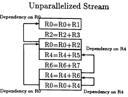
Unparallelized Stream
Dependency
onRnR0=R0+R1
R2=R2+R3
R0=R0+R2
R4=R4+R5
Dependency
onR4
R6=R6+R7
Dependency
onRo
R4=R4+R6
R0=R0+R4
Dependency
onR4
Parallelized Stream
R0=R0+R1; R2=R2-fR3; R4=R4+R5;
R6=R6+R7
R0=R0+R2;
R4=R4+R6
R0=R0+R4
Figure
1.1.
Taking
Advantage
of
Implicit Parallelism in Instruction Traces
In
the
unparallelized stream
the
dependencies
between
the
different
instructions
are annotated.
In
the
bottom
stream, the
instructions
have
been
parallelized.This
stream
was
parallelizedoptimally
so
nowany
instruction in
the
parallelized streamhas
a
dependency
with
one
of
the
instructions
immediately
preceding it.
The
parallelized
stream executesin 3
clockcycles
whereasthe
unparallelized streamrequires
7
clock
cycles.
The
numberof
clockcycles
neededto
execute
the
code
slices
can
also
be
termed
the
run
length.
The
side
effects
from
executing
either
piece of
code
is identical.
To
comparethe two
streams,
a metric of
speedup
and
compression can
be
com
puted.
Speedup
is defined
as
s
=Ru
Rr
[image:14.552.66.288.50.219.2]com-5
pressed.
In
Figure
1.1 the speedup
is
\.
Compression
is
a measure of
how
much
the
parallelized
run
length decreased
in
size and
is
defined
as
C=R,-For
a single run
length
it is
true that
c=1-.
s
Given
a
series of
instructions
from
an
instruction
stream,
Keller[3]
formalized
the
conditions
in
which
instructions
can
be
executed
in
parallel.
The instructions
are assumed
to
be
in
the
following
format.
i:
OP, 51, 52,
D
Where
i is
the
instruction
label,
OP
is
the
instruction
operation,
51
and
52
are
the
source
registers,
and
D is
the
destination
register.
The resulting
operation
performed
by
the
instruction is
as
follows:
i:D*-SlOP
52
For
each
instruction in
the stream,
a range anddomain
can
be defined.
The
range
is
the registers, memory,
or
condition
codes
modified
by
the
instruction.
That
is,
the
range
is
the
side effect of
the
instruction. The
domain
is
the registers,
memory,
or condition codes referenced
by
the
instruction.
If i
and
j
are
two
different instructions
in
an
instruction
stream, then
i
and
j
can
be
executed
in
parallel
if
and
only
if
all
the
following
conditions are
true.
range(i) D
domain(j)
=0
range(i)
D
range(j)
=0
The first
condition
requires
that
instruction
t's side effects not
be
referencedby
instruction
j
.If
this
were not
so,
a race
condition
would exist on
the memory,
regis
ters,
and
condition codes referenced
by
instruction
j. The
second condition asserts
the
reverse of
the
first
condition.
The
third
condition prevents
raceconditions
that
would exist
if
instructions
i
and
j
had
the
same side effects.
Keller
further describes
the
condition
that
leads
to
optimal parallelization.
Principle
of
Optimality: Whenever
j
is
an
operation
corresponding
to
an
instruction
in
the
instruction
stream,
and
there
is
no
preceding
operation
i
that
is
being
executed or
is pending
execution suchthat
i
and
j
cannot
be
parallelized,
then
j
should
be
issued.
The resulting
parallelized
instruction
stream
may
require
instructions
to
execute
in
a
different
order
than originally
found
in
the code,
andmay
requireany
numberof
instructions
to
be
executed
in
asingle clock cycle.
1.3.2
The Effective Scope
of
Implicit Parallelism
Ideally,
optimal
speedup
would
occur
if
the
scope parallelizedwas
the
entire
execution
trace
of
the
program.This
would result
in
atrue
data flow
ofthe
programsuch
that
all operations
would occur
assoon
as
their
operandswere available.
To
accomplish
this
in hardware
wouldbe
prohibitively
expensive.The
hardware
would
be
required
to
search
the
entire execution
trace
for
nonrelated
activities,
and
then
execute
them
in
parallel.A
more
simplistic viewof
parallelizationis
usually taken
where
run
length
compression
only
occurswithin
basic blocks.
A basic block
is
a seriesof
instructions
that
will
not
requirethe parallelizing
processorto
follow
morethan
one
possible
branch.
To
parallelize
past
a
condition
branch
would
requirethe
processorto
execute
both
streams after
the
branch,
and
then
drop
the
resultsof
the
unneededone once
the
condition code
dependency
of
the
branch
instruction
is
resolved.Of
course, any
number of conditional
branches
could
be
encountered,
resulting
in
anexponential
explosion
in
the
number of streams
being
parallelized at once.The basic
block for
the
SPARC
architecture
is delimited
by
the
following
in
structions:
1.
conditionalbranches
2.
procedurecalls
3.
entriesinto
the operating
systemThe
secondtwo
delimiters
alleviatethe
needfor
parallelizing
in
morethan
oneregister
set
at
a
time
(a
characteristic ofthe
SPARC
architecture.)
Section
1.3.7
further details
each case.1.3.3
The Effects
of
Compiler
Technology
on
the Extent
of
Implicit
Parallelism
Undoubtedly,
the
compilertechnology
usedto
generate executables affectsthe
amount
of
implicit
parallelism availablein
the
dynamic
instruction
traces.
For
ex
ample,
a
compilerthat
performedregister allocationin
a
low
registerto
high
registerfashion
(i.e.
RO, Rl; RO, Rl, R2, R3; RO,
...) would not provideas much
implicit
parallelism
as
a
compilerthat
performed round-robin register allocation(i.e.
RO,
Rl-R2
R3
R3, R4;
R6,
)Tms is
because
in
the
latter
case unrelated operationswould more
likely
be
in different
registers,
thus reducing
the
dependencies between
the
operations.In
this
thesis,
speedup
will
be
measuredanalytically
and
empirically
for
the
Software Foundation
version
1.37.1
ANSI C
compiler,
TeleSoft
version
1.25
Ada
compiler,
and
Xerox
version
l.H
Cedar/Mesa
compiler.
All
these
compilersuse
different
code
generators
and
optimizers, thus it
will
be
possibleto
see
the varying
effects
on
speedup
due
to
compiler
technology.
The
Dhrystone benchmark is
a
synthetic
benchmark.
It is
crafted
to
look like
a
statistically
"average" program.Analyzing
this
program will ensure all
frequent
operations are
included.
1.3.4
Instruction Issue Logic
The instruction
issue
logic
is
responsible
for
deciding
when
an
instruction
can
be
executed.
To
do
this the
hardware
must
determine if
the
following
conditionshave
been
met:
The
instruction
issued
must
not
shareany
dependencies
with
any
otherin
structions
currently executing,
or
any
of
the
instructions
preceding
it.
The
appropriate
hardware
to
perform
the
instructions
function
mustbe
available.
The
logic
discussed in
this thesis
will
allow multipleinstructions,
possibly
not
sequential, to
be
issued
perclock
cycle.Instructions
are
issued
to
functional
units.The functional
units perform
the
desired function (i.e.
multiply,
add,
square
root.)
A
designer
of
any
instruction issue
unithas
two
degrees
of
freedom:
sequential
vs.
non-sequentialinstruction issue
single
vs. multipleinstruction issue
per clock cycle
During
each
clock
cycle,
it is
the
responsibility
of
the
instruction
issue logic
to
dispatch
instructions to
a
functional
unit.Once
an
instruction
is
issued
to
a
9
be
used
again.
Often,
a
number
of
functional
units
are
available,
allowing the
processor
to
support
a
number
of
instructions executing
in
parallel.Pipelining
functional
units can also
increase
the
number of
functional
units available.If the
instruction
issue capability is limited
to
only
sequential
issue,
instruction
stream
parallelization
will
be limited
to
neighboring
instructions.
By issuing
in
structions out of
order,
the
processor can
increase its
chances
of
locating
another
instruction
that
is
not
dependent
on
the
instructions
currently
executing,
or
the
instructions
preceding it.
The
area of
look
ahead
in
which
instructions
arechecked
for
dependencies
is
the
instruction
window.
Supporting
out of order execution
introduces
the
problem of
imprecise interrupts.
When
an
interrupt
occurs,
the
state
that
needs
to
be
saved
is
no
longer just
the
program
counter,
but
now
is
the
state
(executed,
or
not
yet
executed)
of
every
instruction
in
the
instruction
window.
This
problemis
further
complicatedfor
synchronous
interrupts like
page
faults
and
divide-by-zero
traps.
Because
anumber
ofinstructions
are
currently
under
execution,
more
hardware is
requiredto
determine
which
instruction
caused
the trap.
Restarting
a process afterinterruption
is
also a complicated procedure.
As
a
result, many
high
performance architectures
do
not
support
virtual
memory,
and
during
synchronoustraps
they
only specify
the
"approximate"location
of
the
offending instruction.
Sohi
proposes
a number
of
hardware
solutions
to
the
problem of
the
imprecise interrupt.
[14]
Another
way to
increase
the
amount of
parallelizationis
to
allowthe
processor
to
issue
more
than
oneinstruction
per
clock cycle.This is
extremely
important
for
integer
instructions,
because
they
typically
canexecute
in
one
clock cycle.A
parallelizing
processorthat
supports multipleinstruction
issue
will
look
at
the
current
instruction
window,
andissue
all
the
instructions
that
do
not
share
dependencies
10
The
specific
configuration
used
for
simulations
in
this thesis
is
the
dispatch
stack.
This
instruction
issue
logic
was
proposed
by
Acosta[l].
It
supports multiple
instruction issues
per
clock
cycle,
and
nonsequential
instruction issue.
1.3.5
The
Dispatch
Stack
The
dispatch
stack uses a window of
instructions from
the
head
of
the
instruc
tion
stream.
As
instructions
are
finished
executing,
the
unfinished,
and
unissued
instructions
are
pushed
to
the
top
of
the
dispatch
stack.
The
hardware
onthe
dispatch
stack
is
responsible
for
resolving
which
instructions
can
be
parallelized,
and whether
the
functional
unit resources are available once an
instruction is
ready
to
execute.
An
implementation for
this
hardware
is
described in
[1].
This issue
logic,
if
given enough
resources,
will converge upon
the
issue
pattern
specified
by
Keller's
Principle
of
Optimality.
When
implementing
a
dispatch
stack, the
architect must
decide how
resourceswill
be
spent.
The dispatch
stack requires
two
resources
to
performits
task.
instruction
window slots
functional
units
The
numberof slots
in
the
dispatch
stack
(its
size) determines how far down
the
instruction
stream
the
issue logic
can
look for
instructions
to
issue. The larger
the
window
the
better
the
chance of
finding
one or more
instructions
to
issue.
The
functional
unit
configurationcan
also
limit
the
amount
of parallelization
that
can
be
exploitedin
the
instruction
stream.
Once
the
issue
logic
determines
that
an
instruction
can
be
issued,
it
must
have
available
the
needed
functional
unit.1.3.6
The SPARC Architecture
The
SPARC
architecturewas
developed
by
Sun Microsystems.
[8]
[9]
It is
loosely
11
processor
has
a
small,
simple
instruction
set
that
supports
both
integer
and
floating
point
operations
in
hardware.
The
processor
was
first
implemented in 1987
by
Cypress
Semiconductor.
SPARC
stands
for
Scalable Processor Architecture.
Because
the
architecture
only
specifies
the
instruction
and
register
set, many
implementations
are possible.
Currently,
Cypress
Semiconductor,
Tl, Fujitsu,
and
BIT have
SPARC
processor
implementations.
Sun
Microsystems
will
sell
UNIX kernels
to
companies
that
produce
SPARC
workstations.
By
using
the
same
UNIX
bindings,
all
the
SPARC
workstations
that
use
SunOS
share
binary
compatibility
for
executables.
Currently,
Sun
Microsys
tems,
Solboume,
Tl,
and
BIT
sell
SPARC
based
workstations.
1.3.6.1
The
SPARC Instruction
Set
The
SPARC
architecture
features
a
simple,
orthogonal
instruction
set.
All
instructions
are
32
bits
in
length, including
any
and all operands.
This
restriction
allows
for
the
development
of
extremely
simple and efficient prefetch mechanisms.
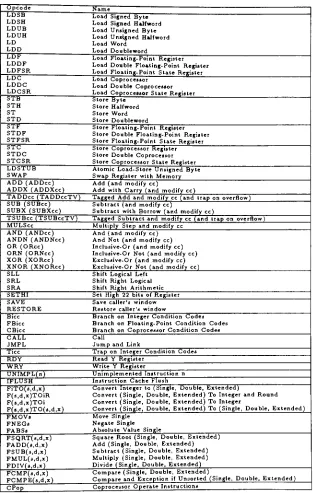
Table 1.1
lists
the
SPARC
instruction
set.
All instructions have
exactly
one
side
effect;
as
a
result,
nospecial
support
is
needed
for
handling
page
faults.
If
a
memory
reference resultsin
afault,
the
instruction
can
be
re-executed,
no
internal
state
needsto
be
saved.
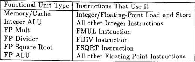
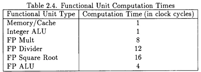
Table 1.2
showsthe
different
types
of
functional
units
required
in
the
SPARC
processor
to
execute
all
the
instruction
types
in
hardware.
Memory
load/store instructions
supportthe
following
addressing
modes.
Effective
Address
=r[rsl]
+
r[rs2]
Effective
address =r[rsl]
+
sign_ext(simml3)
If
one
of
the
register
sourcesis
not
required,
the
global register gO
can
be
used
12
Table
1.1.
The
SPARC
Instruction Set
Opcode Name
LDSB Load Signed Byte LDSH Load Signed Halfword LDUB Load Unsigned Byte LDUH Load Unsigned Halfword
LD Load Word
LDD Load Doubleword
LDF Load Floating-Point Register LDDF Load Double Floating-Point Register LDFSR Load Floating-PointStateRegister LDC Load Coprocessor
LDDC Load Double Coprocessor LDCSR Load CoprocessorState Register
STB StoreByte
STH StoreHalfword
ST Store Word
STD StoreDoubleword
STF StoreFloating-Point Register
STDF Store Double Floating-Point Register STFSR StoreFloating-Point State Register
STC StoreCoprocessor Register STDC Store DoubleCoprocessor STCSR StoreCoprocessorStateRegister LDSTUB Atomic Load-Store UnsignedByte
SWAP
Swap
RegisterwithMemory
ADD(ADDcc)
Add(andmodify cc)ADDX
(ADDXcc)
AddwithCarry
(andmodify cc)TADDcc
(TADDccTV)
TaggedAddandmodifycc(and traponoverflow) SUB(SUBcc)
Subtract(andmodify cc)SUBX
(SUBXcc)
SubtractwithBorrow (and modify cc)TSUBcc
(TSUBccTV)
Tagged Subtractandmodifycc(and traponoverflow) MULSccMultiply Step
andmodifyccAND
(ANDcc)
And (and modify cc) ANDN(ANDNcc)
And Not(andmodify cc)OR
(ORcc)
Inclusive-Or (and modify cc) ORN(ORNcc)
Inclusive-Or Not (and modify cc) XOR(XORcc)
Exclusive-Or(andmodify cc) XNOR(XNORcc)
Exclusive-Or Not (and modify cc)SLL Shift Logical Left SRL Shift Right Logical
SRA Shift Right Arithmetic
SETHI Set High 22 bitsofRegister SAVE Savecaller's window
RESTORE Restorecaller'swindow
Bice Branchon IntegerCondition Codes FBicc BranchonFloating-Point Condition Codes
CBicc BranchonCoprocessor ConditionCodes
CALL Call
JMPL
Jump
andLinkTicc
Trap
onIntegerConditionCodes RDY ReadY RegisterWRY Write Y Register
UNIMPL(n)
Unimplemented Instruction nIFLUSH Instruction Cache Flush
FiTO(s,d,x)
ConvertIntegerto(Single, Double, Extended)
F(s,d,x)TOiR Convert
(Single,
Double,Extended)
ToIntegerandRound F(a,d,x)TOi Convert(Single, Double, Extended)
ToIntegerF(s,d,x)TO(s,d,x)
Convert(Single, Double,Extended)
To(Single, Double, Extended)
FMOVi Move SingleFNEGa Negate Single
FABSs Absolute Value Single
FSQRT(s,d,x)
SquareRoot(Single,
Double,Extended)
FADD(s,d,x)
Add(Single,
Double,Extended)
FSUB(s,d,x)
Subtract(Single, Double,
Extended)
FMUL(s,d,x)
Multiply
(Single, Double,Extended)
FDIV(s,d,x) Divide
(Single, Double, Extended)
FCMP(s,d,x)
Compare(Single, Double,Extended)
[image:22.552.94.407.136.629.2]Table
1.2.
Functional Units
Used
in the
SPARC
Processor.
Functional Unit
Type
Instructions
That
Use It
Memory/
Cache
Integer/Floating-Point
Load
and
Store
Integer ALU
All
other
Integer
Instructions
FP Mult
FMUL Instruction
FP Divider
FDIV
Instruction
FP
Square
Root
FSQRT Instruction
FP
ALU
All
other
Floating-Point
Instructions
13
All
arithmetic
instructions
use
the
following
three
register
format.
r[dest]
=r[rsl]
OP
r[rs2]
r[dest]
=r[rsl]
+
sign_ext(simml3)
To load
small
immediate
values,
add sign-ext(simml3)+g0
into
the
destinations
register,
where
gO
will
supply
a
0
value.
To
load large immediate
values
into
registers, the
SETHI
instruction loads
a22
bit
valueinto
the
highest 22 bits
of aregister,
and zeros
the
lower
10
bits.
If
the
lower
10
bits
needto
be
set,
another add
instruction is
required.This
strategy
supports small
integer
loads in
one
instruction,
while
allowing
for
32 bit immediate
loads
with
32
bit length
instructions
using
2
instructions.
Multiply
instructions
are
only
partly
supported
in hardware.
A
simple
step
instruction
allows a32x32 bit
multiply to
be implemented in 36
clock cycles.Integer
division is
not
supportedin hardware.
Branch instructions
support
a
22
bit,
sign
extended
offset
from
the
currentPC,
and
call
instructions
support
a
30
bit
sign
extended offset
from
the
currentPC.
Branch
and call
instructions
each
have
one
delay
slot
immediately
following
the
execution
of
the
branch
or
call.
The instruction in
this
slot
is
executed whether
[image:23.552.110.442.99.205.2]14
implementations.
The
SPARC
architecture
also
supports
an
"annul"
bit
for
condi
tional
branch
instructions.
This bit
specifies
that the instruction in
the
delay
slot
will executed as a
NOP
instruction
if
the
branch
is
not
taken.
This
option
allowscompilers
to
move
the
first
instruction
in
a
loop
to the
delay
slot,
thus
increasing
the
chance of
finding
a useful
instruction.
Also included
are
frame
handling
instructions
and
tagged
operations.Tagged
instructions
are
intended for
use
in
dynamically
typed
environmentslike LISP
and
Smalltalk.
They
perform
arithmetic operations on
30 bit
operands.The
2
least
significant
bits
are reserved
for
auser
defined
tag.
If
the two tags
do
notmatch
for
any
operation,
an overflow error will occur.
1.3.6.2
The SPARC Register
Set
The
other
interesting
feature
ofthe
SPARC
architectureis
the
register set.The
architecture uses register windows.
For
any
procedure scope
the
processor provideseight
32
bit
global
registers,
eight
32
bit local
registers,
eight
32
bit
registers
for
procedure
input
parametersfrom
the
caller(ins),
and
eight32
bit
registers
for
parameters
to any
procedure
that the
current procedure calls
(outs).
The
register windowworks
in
a
circularfashion. When
a procedure calls another
procedure, the
new
procedure'sins
arethe
out's of
the
previousprocedure,
andthe
called
procedurealso
receives
its
own
setof
eight32
bit locals.
All
procedures
share
accessto
the
same eight32
bit
global
registers.Unlike
the
UC
Berkeley
RISC
implementation,
the
register windowis
notmapped
into
the
address space of
the
processor.Underflow
and overflow supportgives software
the
appearance
that
there
arean
unlimited number of register windows.The
SPARC
specification
only
states
that the
numberof
real windowscan
vary
from 2
to
32.
The
register#0
is
a
special registerfor
extending the
flexibility
of
many
in
15
a one
register
or
immediate
only
address
mode
is
needed.
When
written
to the
information
is
discarded.
This
is
useful
for
implementing
a
compareinstruction
by doing
a
subtraction
that
modifies
only the
condition
code
by
specifying
the
destination
of
the
arithmetic
operation
to
be
#0.
1.3.7
SPARC
Characteristics
That Limit Run
Lengths
Along
with
the
conditional
branch,
the
SPARC
architecture also
delimits
paral-lelizable
run
lengths by:
procedure calls
entries
into
the
operating
system
Procedure
calls on
the
SPARC
architecture create a
hurdle for
issuing
instruc
tions.
Even
though
the
call
instruction
is
unconditional,
it
resultsin
the opening
of
a
new
register
set.
If
an
instruction
from
the
current
and
nextregister
set
are
to
execute
in
parallel, the
processor
hardware
mustbe
ableto
referenceboth
register
sets,
and
realize
for
dependency
checking
that
they
are
indeed different.
And for
significantly
large dispatch
stacks, any
number of register
sets
could
be
active at
any
one
time,
resulting in
references
to
real
registers,
and
registers
that
have
over/underflowed
into
memory.
An
entry
into
the
operating
system
is
accomplishedvia
the
trap
instructions
andalso
causesa
newregister set
to
be
opened.As
a
result, this
operation
will
alsoCHAPTER
2
RESEARCH
DESCRIPTION
2.1
Capturing
SPARC Instruction
Traces
SPARCTrace
is
a program
that
has been developed
for capturing
SPARC
pro
cessor
instruction
traces.
See
Appendix
A for
user's
documentation.
It is
a general
purpose
trace
tool that
creates
execution
traces
with
sufficientinformation
such
that
asimulator could
later
re-execute
the trace.
An
executiontrace
is
a complete
record of all
instructions
to
pass
through the
execution stage of
the
processor
during
the
execution of a program.
These
traces
can
be
very
large for
someprograms.
The
tool
is implemented
on
SunOS
4.x,
thus
it
will
only
execute on machines
that
share
binary
compatibility
with
the
Sun SPARC
workstation series.
Figure
2.1
details
operation of
the
SPARCTrace
program.
The
traced
program
runs without
knowledge
that
it is
being
traced.
Its
Stdln, StdOut,
and
StdErr file
streams remain
intact. SPARCTrace
uses
the
Unix PTRACE
system
callto
impose
its
control over
the
program
being
traced.
Any
SPARCTrace
informational
output
is
inserted
into
the
StdErr
stream of
the
programbeing
traced.
Instruction
stream
information
is
piped
to
anotherC-Shell's Stdln
stream.A
SPARCTrace
command
line
option allowsthe
userto specify the
C-Shell
command
line
that
willaccept
the
instruction
trace
stream
on
its
Stdln
stream.
2.1.1
Limitations
of
SPARCTrace
A
number of
limitations
exist whichlimit
the
effectiveness ofthe
SPARCTrace
17
Stdln
SPARCTrace
\
X
Instruction
Stream/Stdln
PTRAOE i
ystemCall
Traced
Program
StdErr
*
StdOut
StdErr
CSH
Command
StdOut
StdErr
Figure
2.1.
SPARCTrace Operation
Because SPARCTrace
uses
PTRACE
to
perform program single
stepping,
it is
unable
to trace
program execution
in
the
operating
system.
As
a
result, traces
willshow
entry
into
the
SunOS
kernel
as
a single
TRAP instruction.
To
supportthe
possibility
of
trace
simulation at
a
later
time,
the
processor
state
is
recorded
into
the
instruction
stream after
returning
from
the
SunOS
call.
A
second
limitation
results
from
the
first. If
a program executed an
EXEC
call
to
fork
off
a new
process, the
SPARCTrace
program'soutput
will not
include
the
forked
program's execution.This is because
the
EXEC
call
is
anentry
into
the
OS
kernel
and
SPARCTrace
cannotfollow
this
operation.2.1.2
Instruction Trace Format
As
instructions
are
executedthey
are
placed
into
the
instruction
stream.
All
SPARC
instructions
are
32
bits,
and
all
operandsare
containedwithin
the
32
bit
[image:27.552.67.485.76.324.2]18
Three
conditions
requirethe
insertion
of control
information
into
the
instruction
trace
stream.
Entry
into
the
operating
system.
Execution
of a
Load/Store Instruction.
Insertion
of
debug
information
into
the
instruction
stream.The
above conditions
insert
their
information
into
the
instruction
stream
through
the
use
ofthe
UNIMPL instruction
opcode.
This is
an
illegal
instruction
that
willnot
be
executed,
so
it
can
be
used
to
flag
control
information in
the
instruction
stream.
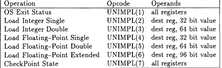
Table
2.1
details
the
illegal
opcodes
used
for adding
control
information
into instruction
traces.
Table
2.1. Illegal
Opcode
Formats Used
for
Inserting
Information
in Traces
Operation
Opcode
Operands
OS
Exit
Status
UNIMPL(l)
all
registersLoad Integer Single
UNIMPL(2)
dest
reg,
32
bit
value
Load
Integer Double
UNIMPL(3)
dest
reg,
64
bit
valueLoad Floating-Point Single
UNIMPL(4)
dest
reg,
32
bit
valueLoad Floating-Point Double
UNIMPL(5)
dest
reg,
64 bit
value
Load Floating-Point Extended
UNIMPL(6)
dest
reg,
96 bit
value
CheckPoint
State
UNIMPL(7)
all
registersWhen
a
program entersthe operating
system,
it
can
nolonger be
traced.
If
later
simulationof
the traces
is
to
be
performed,
the
state ofthe
processormust
be
captured and
storedinto
the trace
afterexiting the
operating
system
trap.
This is
required
because SPARCTrace
cannottrack
what
has
changeshave
occurredto the
processor state within
the operating
systemtrap.
By
saving
the
post
trap
processor
[image:28.552.94.461.389.502.2]19
Of
course
the
actual
side effects
that
the
operating
system call
may
have
pro
duced
are
lost. But for
all
normal
programs, the total
side
effectof
any
operating
system call
is
reflected
by
a change
in
processor state
(i.e.
registerresults),
which
we
captured
above,
and
a
change
in
memory
(i.e.
disk
read resultsin
a
buffer),
which we capture
during
load
and store operations.
Whenever
an
integer
or
floating
point
Load/Store
operation executesthe
simulation
can expect a
memory
value
to
follow
the
operation.
This
will give
any
later
simulation
the
same view of
memory
as
in
the
original
trace
execution.The last
piece of
information inserted
into
the trace
streamis
debug
information.
This
information
consists of processor state
dumps,
which
willhere
onbe
referredto
as
checkpoints.
Any
later
simulation can
verify
its
operationby
comparing
its
processor
state
to any
checkpoint
it
encounters.
If
the two
differ,
the
simulatoris
broken,
and
the
checkpoint
interval
can
be increased
through retracing
untilthe
simulator
bug
can
be located.
2.1.3
SPARCTrace
Internals
SPARCTrace
performs
instruction
tracing
through
useof
the
PTRACE
Unix
system call.
PTRACE
allows
SPARCTrace
to
start another process suchthat
its
execution
is halted
until
SPARCTrace
specifiesthat
it
shouldrun.
Unfortunately,
the
Sun-4 SPARC
implementation does
not supportany
singlestep
operationsin hardware.
As
a
result,
SPARCTrace is
requiredto
compute all
the
possiblenext
addresses and putbreakpoint instructions into
these
locations.
Then SPARCTrace
will
resume executionof
the
program,
it
will
execute onein
struction,
then
executea
breakpoint instruction
whichhalts
the
programbeing
traced,
and
resumesthe SPARCTrace
program.After
each
instruction
step,
the
32 bit
instruction
is inserted into
the trace
20
through
the
use of
the
POPEN
system
call.
The
user
specifies on
the
command
line
of
SPARCTrace
what
CSH
command
will
be
executed.
SPARCTrace
make
5
operating
system calls
for
every
single
instruction
traced.
This
makes
the
tracing
operation
very
slow
since
operating
system entries are
very
expensive
on
the
SPARC
architecture
due
to
the
large
number of user
registers.
To
help
reduce
the
number
of system calls
required
for
each
instruction
step, there
is
a
cache
between
SPARCTrace
and
the traced
programs
code
segment.This
reduces
the
number of
system
calls required
to
read
the
instruction
opcode
before
it is
overwritten
with
a
breakpoint
instruction.
Table
2.2
shows
speedup
due
to
adding
the
code segment cache.
Another
operating
systementry
was
removedby
calculating
the
next
program counter value whenever possible.
This
removedthe
need
to
read
the
traced
program's registers.
Under
circumstances wherethe
nextprogram
counter
value
depends
on
register
or
memory
values(i.e.
returnfrom
procedure,
or call
through register)
an
operating
system call
is
made
to
determine
the
next value of
the
program counter.
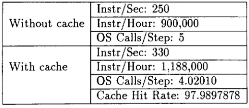
Table
2.2.
Speedup
Gained
by
the
Addition
of
the
Code
Segment Cache
Without
cache
Instr/Sec: 250
Instr/Hour: 900,000
OS
Calls/Step: 5
With
cacheInstr/Sec: 330
Instr/Hour: 1,188,000
OS
Calls/Step: 4.02010
Cache Hit Rate: 97.9897878
2.2
Selecting
Programs
To
Trace
A
number
of
categorieswere
identified
for
determining
which programs
to
select
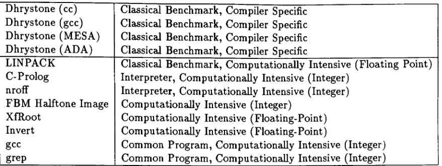
[image:30.552.154.399.461.568.2]21
Classical benchmarks.
Commonly
used
programs.
Computationally
intensive
programs
(both integer
and
floating
point.)
Interpreters
of other
languages.
Programs
developed
under
different
compilers.
Classical
benchmarks
were
selected
because
they
arecommonly
cited
in
other
papers
that
study
architectural performance
enhancements.
Commonly
used
pro
grams will show
the
most
benefit
to the user,
and
computationally
intensive
programs
were
selected
because
these
programs
will
gain
the
most
benefit
overall.
Lastly,
a number of programs under
different
compilers were
selectedto
determine
if
different
compiler
technologies
affect
the
amount of
implicit
parallelism
that
canbe
exploited.
2.2.1
The Test Set
Table
2.3
details
the test
set
selected.
It
shows
the
program
name,
and
the
category
that
program
is
classified under.
The Dhrystone
benchmark[7]
is
a syntheticbenchmark
designed
to
perform
actions
like
an
"average"
program.
It
will
be
usedto
investigate
the
differences
in
speedup
due
to
compilertechnology.
The LINPACK benchmark
performs avariety
of
floating
pointscalar and vector
operations.The
C-Prolog
interpreter
willbe
running
a
programexercising the
append,
member,
length,
and
'+'functions.
The
nroff
text
processorwill
be
formatting
the
"detex"
manual
page.
Gcc,
the
Free Software
Foundation
version1.37.1
ANSI
'C
compiler,
will
be
compiling
the
Dhrystone benchmark.
Grep
will
be
searching
for
the
word
'test'in
the
TeX
22
Table
2.3.
The SPARC
Instruction
Trace
Test Set
Dhrystone
(cc)
Dhrystone
(gcc)
Dhrystone
(MESA)
Dhrystone
(ADA)
Classical
Benchmark,
Compiler
Specific
Classical
Benchmark,
Compiler
Specific
Classical
Benchmark,
Compiler
Specific
Classical
Benchmark,
Compiler
Specific
LINPACK
C-
Prolog
nroff
FBM Halftone Image
XfRoot
Invert
gcc
grep
Classical
Benchmark, Computationally
Intensive
(Floating Point)
Interpreter, Computationally
Intensive
(Integer)
Interpreter,
Computationally
Intensive
(Integer)
Computationally
Intensive
(Integer)
Computationally
Intensive
(Floating-Point)
Computationally
Intensive
(Floating-Point)
Common
Program, Computationally
Intensive
(Integer)
Common
Program,
Computationally
Intensive
(Integer)
a
760x450x8
gray
scale
image
of
the
Hubble
space
telescope
to
a1000x1000x1
bitmap. XfRoot is
an
X
based
program,
which producesa
fractal
patternfor
the
root window of an
X
display.
Invert is
fortran
programthat
determines
the
inverse
of a
10x10
matrix.
All
the
programs
are
run
such
that their
executionis deterministic.
For
the
programs
that
used random
numbergeneration, the
softwarewas
modifiedso
that
the
same random
samplesare used
for
each
invocation
of
the
program.
2.3
Analysis
of
SPARC
Instruction Traces
This
sectiondetails
the three
stepsof
research performedin
this
thesis.
2.3.1
Speedup
with
Unlimited Resources
The
first
phaseof
researchdetermines
the
extent of parallelism availablein
the
SPARC
instruction
traces
if
no
resourcelimits
areimposed
on
the
processorexecution.
This
information
will providea
benchmark
uponwhich
the
resource
[image:32.552.59.498.104.269.2]23
unlimited
processor
will
have
an
infinite
number
of
functional
unitsavailable
atany
time,
and
it
will
look
ahead
as
far
as
needed
given
that
the
following
restrictions
are
observed.
1
The
processor
will
not
look
down
two
instruction
streamsif
a
conditionalbranch
is
encountered.
Instead,
it
will
halt
the
issuing
of
instructions
past
the
conditional
branch
until
the
condition
code
dependency
is
resolved.
The
processor
will not
issue
instructions
past
a
CALL
instruction
untilafter
it
has
executed.
The
processor will not
issue instructions
past
aTRAP instruction
until afterit
has
executed.
A
number of other assumptions are made
concerning
the
processor
implementa
tion that
have
an
impact
on
the
parallelizing
algorithm:
1.
All
non-floating
point
instructions
take
one clock
tick to
execute.
2.
All float
point
instructions
execute
in
the
samenumber of clock
ticks
asthe
Cypress
7C601
SPARC
implementation.
3.
All
memory
reference
instructions
execute
in
one clock
tick.
4.
The
registerfile
contains enough
portsto
supportthe
sinking
andsour