Elsevier Editorial System(tm) for NeuroImage Manuscript Draft
Manuscript Number: NIMG-18-863R1
Title: A bi-planar coil system for nulling background magnetic fields in scalp mounted magnetoencephalography
Article Type: Full length article Section/Category: Analysis Methods
Corresponding Author: Professor Richard Bowtell, PhD
Corresponding Author's Institution: University of Nottingham First Author: Niall Holmes, MSci
Order of Authors: Niall Holmes, MSci; James Leggett, PhD; Elena Boto, MSc; Gillian Roberts, MSci; Ryan M Hill, MSci; Tim M Tierney, PhD; Vishal Shah, PhD; Gareth R Barnes, PhD; Matthew J Brookes, PhD; Richard Bowtell, PhD
Abstract: Small, commercially-available Optically Pumped Magnetometers (OPMs) can be used to construct a wearable Magnetoencephalography (MEG) system that allows large head movements to be made during recording. The small dynamic range of these sensors however means that movement in the residual static magnetic field found inside typical Magnetically Shielded Rooms (MSR) can saturate the sensor outputs, rendering the data unusable. This problem can be ameliorated by using a set of electromagnetic coils to attenuate the spatially-varying remnant field. Here, an array of bi-planar coils, which produce an open and accessible scanning environment, were designed and constructed. The coils were designed using a harmonic minimisation method previously used for gradient coil design in Magnetic Resonance Imaging (MRI). Six coils were constructed to null Bx, By and Bz, as well as the three dominant field gradients dBx⁄dz, dBy⁄dz and dBz⁄dz. The coils produce homogeneous (within ±5%) fields or field
gradients over a volume of 40 x 40 x 40 cm3. This volume is sufficient to contain an array of OPMs, mounted in a 3D-printed scanner-cast, during basic and natural movements. Automated control of the coils using
reference sensor measurements allows reduction of the largest component of the static field (Bx) from 21.8 ± 0.2 nT to 0.47 ± 0.08 nT. The largest gradient (dBx/dz) was reduced from 7.4 nT/m to 0.55 nT/m. High precision optical tracking allowed experiments involving controlled and measured head movements, which revealed that a rotation of the scanner-cast by ±34° and translation of ±9.7 cm of the OPMs in this field
Professor Michael Breakspear Editor-in-chief
NeuroImage Editorial Office Elsevier, Inc.
525 B Street, Suite 1900 San Diego, CA
USA.
20th June 2018
Dear Professor Breakspear,
Please find attached our revised article ‘A bi-planar coil system for nulling background magnetic fields in scalp mounted magnetoencephalography’ by Niall Holmes, James Leggett, Elena Boto, Gillian Roberts, Ryan Hill, Tim Tierney, Vishal Shah, Gareth Barnes, Matthew Brookes and Richard Bowtell. We have changed our manuscript in accordance with the referees’ suggestions and we feel it is much improved as a result. A point-by-point response to the issues raised is attached. We submit our manuscript to be considered for publication as a regular article in NeuroImage. I can confirm on behalf of the authors that this is original work that has not been published, nor submitted previously to any other journal. We look forward to your response.
Yours Sincerely
Professor Richard Bowtell
Sir Peter Mansfield Imaging Centre School of Physics and Astronomy
Professor Richard Bowtell
Sir Peter Mansfield Imaging Centre School of Physics & Astronomy University Park
Nottingham NG7 2RD UK
Tel +44(0)115 951 4737 Fax +44(0)115 951 5166
Highlights:
The design and use of bi-planar coils for magnetic field
nulling is described.
Field nulling allows large subject movements during
on-scalp MEG recordings.
Optical tracking shows high quality data can be acquired
during these movements.
A novel measurement of retinotopy where the subject
We thank the reviewers for their constructive comments on our manuscript. We respond below to the various points that they have raised and highlight the changes which we have made to the manuscript in response. Our responses are in bold typeface.
Reviewer #1: Review of manuscript NIMG-18-863 "Bi-planar coil system for nulling background magnetic fields in scalp mounted magnetoencephalography" by Niall Holmes et al.
Overall assessment
This is an important documentation of the methods this group employed to reduce the static remanent magnetic field and its gradients inside a magnetically shielded room. The purpose of the suppression methods was twofold: (i) to reduce the static field to a level where the sensitivity of the optically pumped magnetometers (OPMs) they used for MEG measurements is not compromised and (ii) to dampen the gradients of the field to allow for head movements together with the wearable system during the measurements.
In designing the bi-planar compensation coils the authors use methods which have been developed in the context of MR imaging in the early 1990s. This method is clearly explained in the paper. Some minor changes are necessary to benefit a reader naïve to this approach, as will be detailed below. The authors tested the performance of the compensation system carefully and performed human measurements. There are, however, some concerns in visual experiment and its analysis as will be pointed out in the detailed comments. Both the introduction and the discussion contain some unfounded statements overemphasizing the benefits of OPM measurements and drawbacks of the present LowTc SQUID systems.
On the basis of the above, the paper needs a moderate revision to be acceptable for publication.
Thank you for the positive overall assessment of the manuscript.
Furthermore, this type of highly technical contribution might reach its target audience more readily if published in, e.g., Reviews of Scientific Instruments.
We’d like to proceed with publication in NeuroImage, because we feel that this will reach the target audience, in particular we wish to include neuroscientists who may be interested in exploiting the capabilities of OPM-MEG.
Also, how is the field nulling system presented here different from the one discussed in a previous paper from the same authors (Nature, 2018)?
The manuscript describes a significant extension of the field nulling work described in the recent Nature paper, and gives a full description of the process of design, construction and testing of the coil system. Specifically, we have added a sixth coil to the system (to generate dBy/dz), and have also enhanced the reference array to allow nulling of the three uniform fields and three dominant field gradients. This has enabled a significant improvement of system performance. We have also now shown that the field nulling system allows MEG recordings to be made with a much larger amount of head motion (±34o of head rotation) than was demonstrated in the previous work. We exploit this larger movement in a visual experiment that would be impossible to carry out in a conventional MEG system due to the extent of the movement required.
Detailed comments
Introduction
1. It is surprising to read that "The resulting 'one size fits all' helmet that is used in current MEG systems …also requires that subjects remain perfectly still while measurements are made." Since the beginning of this century methods to measure and to take into account the head movements have been developed, most prominently by Taulu et al. These methods have also been tested in practice both in basic neuroscience and clinical studies. Furthermore, it has been even argued (Wehner et al., Neuroimage, 2008) that natural head movements may not pose a severe problem in many types of studies. A more balanced view should be provided. In particular, allowing head movements both in the stationary conventional MEG systems and in the wearable OPM system pose technical challenges, which is the very reason why this paper has been submitted for publication.
We have taken these comments on board. We agree completely that, for relatively small head movement, within the confines of the MEG helmet, a number of valuable methods for compensation exist. However, larger movement (e.g. of the head away from the helmet) remains a problem because such movement can bring about a loss of signal which cannot be compensated in post processing. We have now changed our introduction to reflect better this argument. This part of the introduction now reads:
“The resulting 'one size fits all' helmet that is used in current MEG systems means that the sensors are not optimally positioned relative to the head, and also limits the amount of head movement that subjects can make during recordings.”
2. In the following sentence it is claimed: "The consequently unnatural environment of current MEG scanners does not allow easy application of naturalistic stimuli and can be inaccessible for many subject groups, such as patients or infants." Despite of this claim, epileptic patients as well as subjects suffering from various disorders, including children, are successfully studied in tens of clinical MEG centers. Again, please tune down the statement.
We agree, and this statement has been toned down. This part of the introduction now reads:
“The consequently unnatural environment of current MEG scanners also does not allow easy application of naturalistic stimuli. Furthermore, it can pose problems in recording from subject groups, such as patients or infants, who find it hard to keep their heads still relative to the MEG sensors. Although several valuable approaches for compensating for head movement within the confines of the conventional MEG helmet have been developed (Nenonen et al., 2012; Taulu et al., 2005; Wehner et al., 2008), large gross motion (e.g. motion of the head away from the helmet) remains a significant problem due to loss of signal, which cannot be compensated in post processing.”
3. Claustrophobia is mentioned on Page 3. In our experience, claustrophobia is rarely a problem with the present MEG systems.
We agree and we have removed any mention of claustrophobia.
Methods
we note that ∇. = 0 and (in the central, current-free region between the planes) ∇ × = 0, so that there are only 5 independent terms in the gradient tensor and a total of 8 coils are required to eliminate the uniform field and all linear terms in the field variation." Since this is a well known basic fact of electrodynamics, it is sufficient to say: "Since in a current-free region both the divergence and curl of the magnetic field vanish, there are only five independent field gradients. Therefore, 8 coils are needed to compensate for the three field components and their gradients." Incidentally, the gradient consists of first order derivatives so that the end of the previous sentence should simply read "…, as well was their gradients." There are no second or higher-order gradients even though such jargon has crept its way to both MEG and MRI literature.
We modified the text of section 2.1 to say:
“Here, the associated design methods were adapted to produce coils which compensate all three Cartesian components of the uniform background static field inside the MSR, as well as their spatial gradients. Initially it appears this would require 12 distinct coils (3 uniform field coils and 9 gradient coils). However, since both the divergence and curl of the magnetic field vanish in a current-free region there are only five independent field gradients. Therefore, 8 coils are needed to compensate for the three field components and their gradients.”
2. In Eq. 6 "DFT" supposedly stands for "Discrete Fourier Transform". Please add note to the text.
We have now indicated in the text in section 2.1 that “2DFT” stands for “two-dimensional Fourier transformation”.
3. Please write out the (linear) optimization problem arising from Eq. 8, and explain how it is solved. The statement "…whose solution is found here by identifying the pseudo-inverse matrix." doesn't tell the specifics.
This has now been done in section 2.1 using new Eqs. [8-11]. The text now reads:
“Here the functional is minimised by choosing the weights which satisfy
The set of derivatives can be cast as a set of linear simultaneous equations in matrix form,
whose solution is found here by identifying the pseudo-inverse matrix. The wire paths of the coils are then extracted as contours of the optimised stream function.”
OPM-MEG Demonstration
While the experiment conducted is not exactly equivalent to conventional retinotopic mapping using flickering stimuli, it would be most interesting to compare the distributions of the beamformer output to those obtained from data acquired with a conventional MEG system from the same subject. This would help resolve some issues with the experiment and its analysis.
We understand this comment, and to an extent we agree with it. However, our worry is that, given the visual stimulus setup that we used, it would be impossible to set up a ‘classic’ retinotopy experiment with the same visual angles (and stimulus size) as the one we report. We think that this would lead vision scientists to criticise our experimental design. Furthermore, this paper focuses on coil design, and a quantification of the extent of movement that the OPM-MEG system allows. The addition of SQUID recordings would require extensive extra methodology which, we think, might detract from our main messages. Finally, a true comparison would require a much greater number of subjects. For these reasons we would prefer not to add data from a conventional MEG experiment.
1. Was there enough data for the data covariance matrix estimates to compute its inverse without regularization, which is commonly applied in beamformer analyses? Depending on the amount of regularization applied, the beamformer maps may actually be closer to dipole scans than a "pure" beamformer.
We apologise for the oversight; the degree of regularisation should have been mentioned in our original manuscript. We did apply regularisation, using the Tikhonov method, with the regularisation parameter set to 0.01 times the maximum eigenvalue of the unregularised matrix. This has now been added into the text of section 2.9 and reads:
“ and were both regularised using the Tikhonov method to produce and , with the regularisation parameter set to 0.01 times the maximum eigenvalue of the unregularised matrix.”
2. I guess the w_l and w_r in the denominators of Eqs. 10 should be w_{l\theta} and w_{r\theta}, respectively.
Thanks - this is correct and the equation has been changed accordingly in section 2.9 and now states: and .
Thanks - this statement has been incorporated into the text of section 2.9.
Results of the OPM-MEG demonstration
"As expected, the areas of largest 8 Hz response in the beamformer images for the two cases localise to opposite sides of the visual cortex. Inspecting the Fourier transforms there are clear 8 Hz responses during periods of stimulus presentation in the corresponding cortex when compared to rest. Looking in the opposing cortex during stimulus presentation reveals no response." It is confusing that from the horizontal MRI slice in Fig. 7 it appears that the peaks of the Pseudo-T statistic on the same level while the coronal slice indicate that they would fall on different horizontal slices. Furthermore, it does not look like that the blue peak is in the (early) visual cortex. A sagittal slice and an additional experiment with a conventional MEG system would help understand this. For now, it looks like the responses are in the contralateral hemispheres in the occipital lobes. Also, the Fourier transforms in Fig. 7 B) and C) supposedly have a unit since they present the individual conditions.
First, as stated above, we think that addition of conventional MEG data would detract from the main message of the manuscript.
We certainly agree that the beamformer images did appear asymmetric. In truth we are not sure why this was, however a likely reason is the spatial extent of the visual stimulus. The visual stimulus used in our original paper was large, and as such would have activated a large amount of cortex. Previous work has shown that the efficacy of the beamformer imaging declines with increasing activated cortical volume (since the dipole model breaks down). This may have led to a relatively poor spatial localisation of the response.
The experiment was therefore repeated with a smaller checkerboard measuring 10 x 10 cm2, sited 50 cm away from the subject subtending a visual angle of 11 x 11°. With this set-up, each check measured 2 x 2 cm and subtended a visual angle of 2.3 x 2.3°. The use of this smaller checkerboard, along with a higher resolution image (we ran the beamformer on a 2mm, rather than a 4mm cubic grid) led to results which, qualitatively, look more symmetric. We have also incorporated sagittal slices into the figure.
Discussion
At the end of the discussion there are again unqualified forward-looking statements which need to be clarified and justified. "The ability to allow subject movement during a recording is a first for MEG, highlighting the potential for a step-change in functional neuroimaging." This obviously refers to allowing the subject move freely together with the sensors rather than within the limited space of a conventional MEG helmet. In addition, it has been possible to record EEG while the subject is moving.
"…assessing brain development across the lifespan; providing invaluable information on the function of the human brain gathered from currently inaccessible subject groups." While there are MEG systems tailored for infant measurements and children of various ages have been recorded with adult MEG systems, a single OPM system would allow optimal measurement setup independent of head size. Please revise the sentence to reflect the facts.
"The system could also have significant clinical application, coupling the reduced purchase and operating costs with the potential to allow simple checks to assess development of diseases, such as epilepsy and schizophrenia amongst others." While operating costs will certainly be lower, the cost of the OPM sensors is still high. Therefore the purchase cost is unknown at the moment. A "simple" clinical test to assess a patient using electrophysiological measurements already exists: the EEG. Furthermore. in particular the diagnostics of epilepsy inevitably requires a complex workout if the viability of surgery under consideration. Therefore, a "simple check" does not seem viable for epilepsy.
We have modified the paragraph at the end of the Discussion in accordance with these suggestions, to focus on the large range of movement allowed by OPM MEG, and better to place in context the claims for the future benefits of OPM-MEG. The end of section 4.2 now reads:
[image:10.595.73.263.83.352.2]“The ability to allow large subject movements (> 10 cm range of head translation and > 10o range of head rotation), and have the sensors move with the head during a recording is a first for MEG, highlighting the potential for a step-change in functional neuroimaging based on
Reviewer #2: General
The manuscript presents a novel approach to record magnetoencephalography (MEG) on a subject who is wearing a scalp-mounted array of optically pumped magnetometer (OPM) sensors. There is some overlap with their recent Nature paper (Boto, et al. 2018), but the new manuscript presents a more in-depth handling of the bi-planar coil design and construction, as well as results from different MEG experiments.
In general, the methods presented in the manuscript narrows the technical gap from single-sensor OPM studies on stationary heads to completely new kind of neuroscientific studies where the subject can move freely inside the magnetically shielded room. This will hopefully boost the development for a wider adoption of the novel OPM-based MEG systems.
Thank you for the positive overall assessment of the manuscript.
Comments and questions 1. Introduction
The limitations of the commercial SQUID-based systems are partly over-dramatized. Despite they need liquid helium it is no longer a bottleneck, thanks to integrated zero-boiloff helium recycling systems (e.g. Koerber 2016, Lee 2017). In addition, most commercial MEG systems include tools for head movement tracking and movement compensation (e.g. Wehner 2008, Nenonen 2012, Larson 2017). Hence the subject does not need to be perfectly still during the recordings, and head movements do not make any subject groups inaccessible to MEG. In fact, sophisticated multichannel signal processing methods for movement compensation and suppression of far-away and nearby interference (see e.g. Taulu 2014) make the SQUID-based systems still more optimal in clinical studies where magnetized material in/on the head can cause very large nearby interference. Suppression of interference of such nearby sources is still nearly impossible with few-channel OPM arrays.
It is however true that the SQUID sensors are inevitably far from the cortex, and that the helmet-shaped dewar restricts possible movement of the head. In these respects, the proposed OPM array is superior to the SQUID systems. However, the main barrier to wider adoption of OPM arrays is still the relatively high cost (~10 kEUR per OPM sensor) and lack of a proper design for multichannel OPM systems. The current manuscript presents some important steps to overcome the technical difficulties and advance the adoption of new scalp-mounted OPM systems.
We agree with these comments. We have modified the Introduction to address the issues raised by the reviewer and have added references relating to tools for head-movement tracking and movement compensation. This section of the introduction now reads:
“The resulting 'one size fits all' helmet that is used in current MEG systems means that the sensors are not optimally positioned relative to the head, and also limits the amount of head movement that subjects can make during recordings. The consequently unnatural environment of current MEG scanners also does not allow easy application of naturalistic stimuli. Furthermore, it can pose problems in recording from subject groups, such as patients or infants, who find it hard to keep their heads still relative to the MEG sensors. Although several valuable approaches for compensating for head movement within the confines of the conventional MEG helmet have been developed (Nenonen et al., 2012; Taulu et al., 2005; Wehner et al., 2008), large gross motion (e.g. motion of the head away from the helmet) remains a significant problem due to loss of signal, which cannot be compensated in post processing.”
2. Methods
for the OPM sensor and using e.g. "interference compensation" (or something of that kind) for the bi-planar coil system?
We agree that this is slightly confusing and have therefore modified the text. However we do not feel the term “interference compensation” is appropriate since it would imply that we are removing temporally varying interference fields, when in fact we remove the static, remnant Earth’s field. We now use the term “field zeroing” when referring to the on-sensor coils and “field nulling” when referring to the bi-planar coil system. This is outlined in the text in section 2.3 by stating:
“Each QuSpin OPM contains a set of three coils which generate three orthogonal fields. These coils can be used to zero the static field components within the vapour cell up to a maximum of value ~50 nT. We note that ‘field-zeroing’ refers to the on-sensor coils zeroing the field over the vapour cell on each OPM, whereas ‘field nulling’ refers to the bi-planar coils nulling the remnant field inside the MSR over the subject and OPM array.”
You applied 18 OPM sensors on the scalp, but it is not mentioned whether the visual experiments were based on recordings a single-sensor mode? In addition, Fig 1 shows the configuration for somatosensory experiments.
We are not sure that we have understood this point, but we assume that the reviewer is asking whether each OPM sensor was used in single-, or dual-, axis mode (i.e. whether we measured only radial field, or radial + tangential fields). We have added the following text in Section 2.7 to make clear that single axis mode was used.
“Magnetic field data were recorded from an array of 18 OPMs which were positioned to provide good coverage of the visual cortex, and each sensor measured a single field component that was radial to the head surface.”
[image:13.595.107.424.502.620.2]We apologise for the oversight in the Figure. The photo in Figure 1 has been changed to show the configuration used for the visual experiments. And is displayed here:
How often do you need "tuning" of the bi-planar coils, is it performed before every experiment or less frequently? And do you need to perform some tuning of the individual OPM sensors for the maximal resonance?
The field nulling is performed at the start of each experimental session, after the subject is seated and the door to the MSR is closed. The nulling takes around 20 seconds to complete and currents are held constant for the duration of the experiment. At the same time, the on-sensor coils of the OPMs operate in their field zeroing mode, and similarly, once the zeroing is completed, the currents in these coils are also held constant.
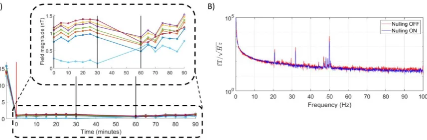
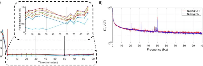
These currents are held constant for the duration of the experimental session (commonly between 30 and 60 minutes in duration). The OPMs require re-zeroing if the ambient magnetic field they experience changes, e.g. when the door to the MSR is opened or they are significantly displaced or reoriented. Additional text and an additional figure (Figure 6), which demonstrate the stability of the field nulling over time, have been added. This was added in response to this comment, and also in response to Reviewer 3, paragraph 3. We have modified the text by adding section 2.6 to the methods and section 3.2 to the results stating:
Methods:
2.6: Field stability
“We devised a simple experiment to demonstrate the stability of the field nulling over time. An array of 7 OPMs was placed inside an empty scanner-cast positioned between the reference sensors. An initial measurement of the static background field was taken with the nulling system switched off. The field nulling was then performed as usual, and the currents applied to the bi-planar coils were set and then held constant. The magnitude of the static background field was measured every 5 minutes over a 30-minute period using the on-sensor coils of the 7 OPMs. The OPMs were then switched off and the door to the MSR opened (none of the experimental equipment was displaced) for 30 minutes, while the currents in the bi-planar coils were still held constant. The sensors were then rebooted and the door to the MSR closed, and the static field was measured every 5 minutes over an additional 30-minute period.
The power spectral density of the OPM signals were also investigated with the field nulling system on and off. A single OPM in the empty scanner-cast was chosen and recordings were completed over 60-s periods. For these measurements, only the radial component of the magnetic field was recorded with a sampling frequency of 1200 Hz. Environmental interference is prominent in these recordings as no interference-reduction methods have been applied to these magnetometer recordings; any additional interference produced by the coils and their associated electronics is therefore easy to identify.”
Results:
3.3: Field stability
“The measured field magnitude is plotted as a function of time in Figure 6A. Analysis of these data shows that the maximum change in field magnitude over the 90 minutes on any sensor was 0.50 nT, while the average (over all 7 sensors) of the standard deviation over time was 0.18 ± 0.03 nT. These values are both smaller than the ±1.5 nT dynamic range of the OPMs, showing that the field nulling achieved was sufficiently stable over the duration of our experiments.
The new figure is provided here:
The cross-talk between the sensors (~3 %) is still relatively high, and probably needs to be corrected before constructing a denser sensor array where the OPMs are closer to each other. Otherwise, one would expect the cross-talk to produce bias in the estimated source locations and amplitudes.
We are working on ways for correcting the effect of cross-talk which, as the reviewer indicates, will be important if we are to be able to use denser sensor-arrays. A brief comment on this has been added to the text of section 2.3 which states:
“Our previous work experimentally verified that cross-talk from currents applied to the on-sensor coils between OPMs at the sensor separations afforded by the scanner-casts is no more than 3 %, which is deemed small enough to be ignored (Boto et al., 2018). As OPM arrays become more dense, the effects of cross-talk will become a growing problem and will require correction methods to be devised.”
3. Results
Despite the movement range is large, how does the method tolerate continuous head movements? Did you perform any comparison recordings to the visual experiment involving two different head positions? It would be interesting to see the results for a single head position (OPM or SQUID array), as well as comparison with EEG mapping (with stationary or two-position experiment).
Why are the responses between lefty and right hemisphere so asymmetric Figure 7; in location, amplitude and spectra?
[image:15.595.89.518.130.271.2]As outlined in the response to Reviewer 1 we agree that the beamformer images appear to be somewhat asymmetric. We have therefore repeated the experiment using a smaller checkerboard and the text has been updated to reflect these changes. The corresponding figure has been updated with new beamformer images, and with sagittal slices provided for clarity. The update figure 9 is provided here:
A brief investigation into continuous head movements was performed using a similar paradigm. We utilised the same checkerboard as before and asked the subject to continually look from the left to the right. The time required to move from left to right (or right to left) was cued using two fixation crosses which appeared in the top left and right corners of the checkerboard.
The cross starts off in the top right hand corner of the checkerboard and after 2 s switches sides, the subject was asked to move their gaze slowly to the cross on the other side. This was repeated 200 times averaged over all trials and arranged to result in 1 s of data where (on average) the subject was looking to the left and 1 s of data where the subject was looking to the right. There was no rest period in the data.
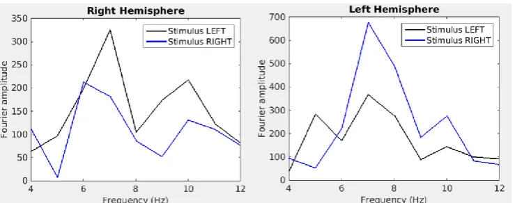
We applied beamformer analysis, contrasting periods when the subject was, on average, looking left to periods when the subject was, on average, looking right. The Fourier transforms of virtual electrodes at locations in the left and right hemispheres shows similar results to the case where the subject remains fixated on a given point (see below).
[image:16.595.74.266.71.338.2]Figure 1) Fourier transforms of the virtual electrode time courses in locations in the left and right hemispheres when the subject continually moved their head. There is a clear increase in amplitude of the ~8 Hz response when the stimulus is presented in the opposing side of the subject’s visual field
[image:16.595.74.444.571.717.2]These results indicate that the OPM-MEG approach we have adopted does tolerate continuous head movement.
The analyzed frequency band of the signal is very narrow (4-12 Hz) and does not demonstrate the performance for studies with wider frequency band of interest.
The band was chosen to show the frequency range where we expected to see a response. The OPMs have a comparable noise figure over the region 1-100 Hz so we expect the performance to be fairly constant over this frequency range. The power spectral density for the OPMs are now included in Figure 6. Previously, we have shown responses in the beta band (Boto et al., 2018).
4. Discussion
Extension to dynamic interference cancellation is probably quite straightforward, if the data acquisition electronics performs rapidly enough to drive the currents on the coils on the basis of the reference-sensor recordings. Similar real-time active compensation techniques could be used than developed for SQUID-based MEG systems, utilizing external compensation coils mounted outside MSR and on the walls inside MSR (e.g. Taulu et al. 2014).
These are important points which were already mentioned to some extent in section 4.1 of the Discussion. We have now added some more text to emphasise this potential future use of the bi-planar coil system. The following has been added to section 4.1:
“Extension to dynamic interference cancellation based on simultaneous recordings from the reference sensors should be relatively straightforward since the relevant interference occurs at relatively low frequency (< 150 Hz) and this approach can build on approaches developed for SQUID-based MEG systems (Taulu et al., 2014).”
Finally, can you summarize what is the main novelty value of this manuscript in comparison to your earlier work presented in the celebrated Nature article?
The manuscript describes a significant extension of the field nulling work described in the recent Nature paper, and gives a full description of the process of design, construction and testing of the coil system. Specifically, we have added a sixth coil to the system (to generate dBy/dz), and have also enhanced the reference array to allow nulling of the three uniform fields and three dominant field gradients. This has enabled a significant improvement of system performance. We have also now shown that the field nulling system allows MEG recordings to be made with a much larger amount of head motion (±34o of head rotation) than was demonstrated in the previous work. We exploit this larger movement in a visual experiment that would be impossible to carry out in a conventional MEG system due to the extent of the movement required.
Details
Fig 1 caption line 5: extra comma "…Three, on-sensor coils…"
This has been corrected.
Page 3, 2nd chapter: I don't quite understand how the head cast would reduce claustrophobia?
We agree and claustrophobia is no longer mentioned.
The sensitivity is “less than 15 fT/√Hz in the 1-100 Hz band” – we have revised the opening lines of section 2.3 to make this clear and it now reads:
“Field measurements were made using commercially-available OPMs (QuSpin, Louisville, CO) which have a sensitivity of <15 fT/√Hz in the 1-100 Hz band, a dynamic range of ±1.5 nT and a bandwidth of approximately 1-130 Hz (Boto et al., 2018; Shah et al., 2018).”
Page 8 bottom: The sensor could record two perpendicular field components, but presumably you only applied one (radial) sensing direction?
We have added text in section 2.7 to indicate that we only recorded radial fields in the visual experiment. It was already stated in section 2.6 that we only recorded radial fields in the experiment designed to demonstrate the allowed range of head movements. The text in section 2.7 now reads:
“Magnetic field data were recorded from an array of 18 OPMs which were positioned to provide good coverage of the visual cortex, and each sensor measured a single field component that was radial to the head surface.”
Figure 2 caption: What is ZFM?
Apologies, ZFM is ‘zero field magnetometer’ which is the product name of the QuSpin sensor. This has been changed to OPM in the caption of Figure 1 and Figure 2.
Page 11 line 1: typo "kin the z-direction)."
Corrected.
Page 13: Subsection nr 2.6 appears twice.
Apologies for this mistake. The section numbering has been corrected.
Page 15 line 9: Reference (Barratt et al 2018) is missing.
Apologies, this paper is in press with Neuroimage. A reference has been added.
Figure 6: Captions of B and C are swapped?
The captions have been put into the correct order.
Page 25, Appendix A: typo "…As the coils deigned here…"
Corrected
References
Boto E, et al. Moving magnetoencephalography towards real-world applications with a wearable system. Nature 555(7698), March 2018 Koerber R, et al. SQUIDs in biomagnetism: a roadmap towards improved healthcare. Supercond. Sci. Technol. 29(11), 2016.
Larson and Taulu. The Importance of Properly Compensating for Head Movements During MEG Acquisition Across Different Age Groups. Brain Topogr. 2017 Mar;30(2):172-181 Lee Y, et al. Low-noise magnetoencephalography system cooled by a continuously operating reliquefier. Supercond. Sci. Technol. 30 (2017) 084003.
Reviewer #3: This manuscript describes a new wearable MEG device able to record brain activity during relatively large head movements. This is possible due to local nulling of the external magnetic field and field gradients thanks to a set coils. The set-up is tested in a visual protocol. The topic is very interesting and MEG devices based on OPMs are highly promising. Overall, the manuscript is well written and details about the field nulling coils are given.
Thank you for the positive overall assessment of the manuscript.
My main concern about this manuscript is about the noise of OPMs in operating conditions. How is the noise figure of OPMs without the additional nulling coils, with OPMs in a fixed position, compared to that with the nulling coils on? Is the noise spectrum similar? Is the actual bandpass affected?
This point has been addressed by adding a figure to the manuscript displaying the power spectral density of a single OPM with and without field nulling applied. The text has been updated to also include details of an experiment we performed to address the second concern, see below.
A second concern is about the stability of the field nulling during time. How long can a measurement last before it is necessary to repeat the nulling procedure?
We perform the field nulling prior to each experiment once the subject has been seated and the door to the MSR closed. Typically a scanning session will last between 30 to 60 minutes with constant currents being applied throughout. We have added to the manuscript details of an experiment to demonstrate the stability of the field nulling over time with results included in a new figure which also addresses the main concern of the noise figure of the OPMs.
To address both points we have modified the text by adding section 2.6 to the methods and section 3.3 to the results stating:
Methods:
2.6: Field stability
“We devised a simple experiment to demonstrate the stability of the field nulling over time. An array of 7 OPMs was placed inside an empty scanner-cast positioned between the reference sensors. An initial measurement of the static background field was taken with the nulling system switched off. The field nulling was then performed as usual, and the currents applied to the bi-planar coils were set and then held constant. The magnitude of the static background field was measured every 5 minutes over a 30-minute period using the on-sensor coils of the 7 OPMs. The OPMs were then switched off and the door to the MSR opened (none of the experimental equipment was displaced) for 30 minutes, while the currents in the bi-planar coils were still held constant. The sensors were then rebooted and the door to the MSR closed, and the static field was measured every 5 minutes over an additional 30-minute period.
Results:
3.3: Field stability
“The measured field magnitude is plotted as a function of time in Figure 6A. Analysis of these data shows that the maximum change in field magnitude over the 90 minutes on any sensor was 0.50 nT, while the average (over all 7 sensors) of the standard time was 0.18 ± 0.03 nT. These values are both smaller than the ±1.5 nT dynamic range of the OPMs, showing that the field nulling achieved was sufficiently stable over the duration of our experiments.
[image:21.595.90.516.260.399.2]The power spectral density of the OPMs with the field nulling on (red) and off (blue) are shown in Figure 6B. There is little difference in the two measurements when the OPMs remain still.”
The new figure is provided here:
Minor issues:
In the abstract there is a typo: "subject moves their head …. their central field of view".
Text changed to avoid plural/singular incongruity.
In the introduction (end of page 2) it is stated that "some OPM sensors contain a set of on-sensor coils which generate magnetic fields along three orthogonal directions within the vapour cell", but no reference is given.
A reference to Shah, V et al Steep Dispers. Eng. Opto-Atomic Precis. Metrol. XI 51. doi:10.1117/12.2299197 has now been added.
Figure 6: A) The static field magnitude as reported by the on-sensor coils for an array of 7 OPM sensors at 5-minute intervals over a 30 minute period. The red line shows when the field nulling was applied, the black lines show a period where the sensors were switched off, and the door to the MSR was left open. There followed an additional 30 minutes where the door was closed and further field measurements were made. The bi-planar coil currents were held constant
A bi-planar coil system for nulling background magnetic
fields in scalp mounted magnetoencephalography
Niall Holmes
1, James Leggett
1, Elena Boto
1, Gillian Roberts
1, Ryan M Hill
1, Tim
M Tierney
2, Vishal Shah
3, Gareth R Barnes
2, Matthew J Brookes
1and Richard
Bowtell
1*
1Sir Peter Mansfield Imaging Centre, School of Physics and Astronomy, University of Nottingham,
Nottingham, NG7 2RD, UK
2Wellcome Centre for Human Neuroimaging, Institute of Neurology, University College London, 12
Queen Square, London, WC1N 3AR, UK
3QuSpin Inc., 331 South 104th Street, Suite 130,Louisville, CO 80027, USA
*Address for Correspondence:
Professor Richard Bowtell,
Sir Peter Mansfield Imaging Centre,
School of Physics and Astronomy,
University of Nottingham, Nottingham, NG7 2RD, UK
Email: richard.bowtell@nottingham.ac.uk
*7. Manuscript
Abstract
Small, commercially-available Optically Pumped Magnetometers (OPMs) can be used to
construct a wearable Magnetoencephalography (MEG) system that allows large head
movements to be made during recording. The small dynamic range of these sensors however
means that movement in the residual static magnetic field found inside typical Magnetically
Shielded Rooms (MSR) can saturate the sensor outputs, rendering the data unusable. This
problem can be ameliorated by using a set of electromagnetic coils to attenuate the
spatially-varying remnant field. Here, an array of bi-planar coils, which produce an open and accessible
scanning environment, were designed and constructed. The coils were designed using a
harmonic minimisation method previously used for gradient coil design in Magnetic
Resonance Imaging (MRI). Six coils were constructed to null 𝐵𝑥, 𝐵𝑦 and 𝐵𝑧, as well as the three
dominant field gradients 𝑑𝐵𝑥⁄𝑑𝑧, 𝑑𝐵𝑦⁄𝑑𝑧 and 𝑑𝐵𝑧⁄𝑑𝑧. The coils produce homogeneous
(within ±5%) fields or field gradients over a volume of 40 x 40 x 40 cm3. This volume is
sufficient to contain an array of OPMs, mounted in a 3D-printed scanner-cast, during basic
and natural movements. Automated control of the coils using reference sensor
measurements allows reduction of the largest component of the static field (𝐵𝑥) from 21.8 ±
0.2 nT to 0.47 ± 0.08 nT. The largest gradient (𝑑𝐵𝑥/𝑑𝑧) was reduced from 7.4 nT/m to 0.55
nT/m. High precision optical tracking allowed experiments involving controlled and measured
head movements, which revealed that a rotation of the scanner-cast by ±34° and translation
of ±9.7 cm of the OPMs in this field generated only a 1 nT magnetic field variation across the
OPM array, when field nulling was applied. This variation could be further reduced to 0.04 nT
by linear regression of field variations that were correlated with the measured motion
parameters. To demonstrate the effectiveness of the bi-planar coil field cancellation system
in a real MEG experiment, a novel measurement of retinotopy was investigated, where the
stimulus remains fixed and head movements made by the subject shifts the visual
presentation to the lower left or right quadrants of the field of view. Left and right visual field
stimulation produced the expected responses in the opposing hemisphere. This simple
demonstration shows that the bi-planar coil system allows accurate OPM-MEG recordings to
1
1: Introduction
Magnetoencephalography (MEG) is a method for non-invasively mapping
electrophysiological activity in the human brain (Cohen, 1968). It produces images of brain
function with high spatiotemporal resolution by measuring the magnetic fields generated
outside the head by neuronal currents in the brain. MEG presents a significant engineering
challenge: the fields generated above the scalp are of the order of tens of femtotesla (fT),
which is more than 109 times smaller than the Earth's magnetic field and orders of magnitude
smaller than other sources of magnetic interference (Hämäläinen et al., 1993). Current MEG
systems employ Superconducting QUantum Interference Devices (SQUIDs) to measure the
very small neuromagnetic fields, and must be housed inside a Magnetically Shielded Room
(MSR) to reduce static and interference fields. Although the sensitivity of SQUIDs is almost
unrivalled, they generally require cooling using liquid helium and so must be operated inside
a dewar arrangement (Hämäläinen et al., 1993). The resulting 'one size fits all' helmet that is
used in current MEG systems means that the sensors are not optimally positioned relative to
the head, and also limits the amount of head movement that subjects can make during
recordings. The consequently unnatural environment of current MEG scanners also does not
allow easy application of naturalistic stimuli. Furthermore, it can pose problems in recording
from subject groups, such as patients or infants, who find it hard to keep their heads still
relative to the MEG sensors. Although several valuable approaches for compensating for head
movement within the confines of the conventional MEG helmet have been developed
(Nenonen et al., 2012; Taulu et al., 2005; Wehner et al., 2008), large gross motion (e.g. motion
of the head away from the helmet) remains a significant problem due to loss of signal, which
cannot be compensated in post processing.
As a result of these limitations, there is considerable interest in developing scalp-mounted
MEG systems, and one particularly promising technology is the Optically-Pumped
Magnetometer (OPM). OPMs use optical pumping of a heated vapour of spin-polarised alkali
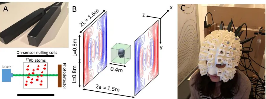
atoms to provide a measure of the local magnetic field (see Figure 1A) (Kastler, 1973). Such
systems offer many advantages compared to SQUID-based systems, including the possibility
of flexible sensor placement on the scalp, a significant increase in sensitivity due to a
reduction in the brain-to-sensor separation and potentially lower purchase and operating
2
“wearable” scalp-mounted MEG system that would allow recordings to be made while the
subject makes large, natural head movements. Simulation studies (Boto et al., 2016;
Iivanainen et al., 2017) have demonstrated the gains in performance which could be achieved
using OPM-based MEG systems. Further, MEG measurements using a small number of OPMs
have been experimentally realised and evoked responses following auditory or
somatosensory stimulation have successfully been detected (Borna et al., 2017; Boto et al.,
2017; Johnson et al., 2010, 2013; Sander et al., 2012; Xia et al., 2006). Additionally OPMs have
been used to detect changes in alpha (8-13 Hz) and beta (13-30 Hz) oscillations (Boto et al.,
2017; Kamada et al., 2015; Sander et al., 2012).
These experimental realisations of OPM-MEG have however involved recording
neuromagnetic fields from restrained subjects, whose heads are fixed in position with respect
to the sensors and surroundings. This limitation arises because the ambient magnetic field
inside the OPM must be less than a few nT in magnitude if it is to operate with the sensitivity
required for MEG, while the residual Earth’s magnetic field inside a MSR used for conventional
MEG is typically a few tens of nT. To avoid this problem, some OPM sensors contain a set of
“on-sensor” coils which generate magnetic fields along three orthogonal directions within the
vapour cell (Shah et al., 2018). These three on-sensor coils can be used to reduce the field
within the cell from tens of nT to less than 1 nT, but such local coils produce fields which show
[image:25.595.76.524.73.240.2]3
a significant fractional variation in amplitude and orientation over the cell. Consequently,
application of large cancellation fields reduces the sensor’s sensitivity by making the field
inhomogeneous over the heated vapour of spin-polarised atoms. More importantly, since the
on-sensor coils compensate the ambient field for a specific location and orientation of the
sensor, any translation or rotation of the sensor which produces a change of the vector field
components that is greater than the nT dynamic range will result in saturation of the sensor
output, rendering the data unusable (until the OPM returns to its original position).
Recently, we have shown that these problems can be avoided by reducing the remnant field
inside the MSR using a larger set of fixed coils that are positioned around the entire OPM
sensor array (Boto et al., 2018). In this approach, coils are mounted on two planes positioned
on either side of the subject to form a bi-planar system, as shown in Figure 1B. Unlike the
tri-axial Helmholtz coil systems (Abbott, 2015) which are commonly used for field cancellation,
this forms an open scanning environment, hence allowing easy access to the scanning area
for the subjects and scanner operators. Our previous work showed that the integration of this
coil system with a head-mounted OPM array allowed MEG data to be recorded whilst a
subject made natural head movements, including head nodding, stretching and drinking tea
(Boto et al., 2018). In the present paper, we describe an enhanced field-nulling coil system,
incorporating six bi-planar coils and a 4-sensor reference array, and provide a full
experimental demonstration of the system’s performance. We begin by providing a detailed
description of the design and construction of the bi-planar coils, using methods adapted from
Magnetic Resonance Imaging (MRI). Specifically, mathematical expressions previously used
for designing planar gradient coils (Yoda, 1990) were incorporated into a harmonic
minimisation approach (Carlson et al., 1992; Turner, 1993). Following this, the efficacy of the
resulting bi-planar coil set is characterised by mapping the residual static magnetic field vector
inside a central region of the MSR, with and without the field nulling. We then demonstrate
the extensive range of subject head motions that can be tolerated whilst maintaining
operation of the OPMs, and show that residual magnetic artefacts in the resulting data can
be markedly reduced by linear regression of head motion parameters that are measured using
an infra-red camera system. Finally, we provide a unique neuroscientific demonstration of
our system which involved instructing a subject to make head movements in order to shift
4
to capture the retinotopic organisation of the human visual cortex, we show that high fidelity,
high spatial resolution MEG data can be measured even in the presence of large subject
movements.
2: Methods
2.1: Theory of bi-planar coil design
Bi-planar field gradient coils have previously been employed in MRI to generate field
gradients in a single component of the magnetic field vector (Haiying, 1998; Martens et al.,
1991; Yoda, 1990). Here, the associated design methods were adapted to produce coils which
compensate all three Cartesian components of the uniform background static field inside the
MSR, as well as their spatial gradients. Initially it appears this would require 12 distinct coils
(3 uniform field coils and 9 gradient coils). However, since both the divergence and curl of the
magnetic field vanish in a current-free region there are only five independent field gradients.
Therefore, 8 coils are needed to compensate for the three field components and their
gradients. Based on analysis of the measured field variation in our MSR we have chosen to
construct 6 coils (3 uniform field coils and 3 gradient coils) which together can produce an
adequate reduction of the remnant field over a central region of the room.
To generate expressions that allow the design of biplanar coils, we consider the magnetic
vector potential 𝑨(𝒓) at position 𝒓(𝑥, 𝑦, 𝑧) due to current distribution 𝑱(𝒓′), which is given
by:
𝑨(𝒓) = 𝜇0 4𝜋∫
𝑱(𝒓′)
|𝒓 − 𝒓′|𝑑3𝒓′ . [1]
If the current is confined to the 𝑥-𝑦 plane at 𝑧 = 𝑎, we can define the surface current density
𝑱 in terms of a two-dimensional stream function 𝑆(𝑥, 𝑦) such that ∇S × 𝒛̂ = 𝑱 (since ∇. 𝑱 = 0).
Then, performing the Green’s function expansion of |𝒓 − 𝒓′|−1 and re-writing the current
density in terms of its two-dimensional Fourier transform, Eq. [1] can be re-formulated as:
𝑨(𝒓) =𝑖𝜇0
2 ∫ 𝑑𝑘𝑥
∞
−∞
∫ 𝑑𝑘𝑦 ∞
−∞
𝑒𝑖𝑘𝑥𝑥 𝑒𝑖𝑘𝑦𝑦 𝑒
−𝑘𝑧(𝑧>−𝑧<)
𝑘𝑟 [𝑘𝑦𝒙̂ − 𝑘𝑥𝒚̂] 𝑆̃(𝑘𝑥, 𝑘𝑦), [2]
where 𝑘𝑟 = (𝑘𝑥2+ 𝑘𝑦2)1/2, 𝑧>,< is the greater or lesser of 𝑧 or 𝑎 and 𝑆̃(𝑘𝑥, 𝑘𝑦) is the
5
opposite current distribution confined to the plane at 𝑧 = −𝑎, so that 𝑆𝑧′=𝑎= ±𝑆𝑧′=−𝑎. Using
Eq. [2] the magnetic field (𝑩 = ∇ × 𝑨) in the region between the planes, −𝑎 < 𝑧 < 𝑎 can be
found by adding the contributions from the current distributions on the two planes:
𝑩̃(𝑘𝑥, 𝑘𝑦, 𝑧) = 𝜇0{[𝑖𝑘𝑥𝒙̂ + 𝑖𝑘𝑦𝒚̂]𝑠𝑖𝑛ℎ
𝑐𝑜𝑠ℎ(𝑘𝑟𝑧) − 𝑘𝑟𝒛̂ 𝑐𝑜𝑠ℎ
𝑠𝑖𝑛ℎ(𝑘𝑟𝑧)} 𝑆̃(𝑘𝑥, 𝑘𝑦)𝑒−𝑘𝑟𝑎. [3]
Here 𝑩̃(𝑘𝑥, 𝑘𝑦, 𝑧) denotes the two-dimensional Fourier transform of the magnetic field over
the 𝑥 − 𝑦 plane at position 𝑧 and the upper/lower 𝑠𝑖𝑛ℎ or 𝑐𝑜𝑠ℎ terms refer to the cases
where the stream function has the same/opposite sign on each plane. The real-space field
variation can be calculated from Eq. [3] via inverse Fourier transformation of 𝑩̃(𝑘𝑥, 𝑘𝑦, 𝑧) .
To design a coil to produce a particular field variation, the stream function can be
parameterised (Carlson et al., 1992), and then the parameter values which yield optimal
performance based on a pre-defined functional can be identified. For the bi-planar coils
considered here, the stream function is parameterised as a two-dimensional Fourier series
which is confined to the region |𝑥|, |𝑦| < 𝐿 (𝑧 = ±𝑎) on the two coil planes, so that:
𝑆(𝑥, 𝑦) = ∑ [𝛼𝑛cos (𝜋
2(2𝑛 − 1) 𝑥
𝐿) + 𝛽𝑛sin ( 𝜋𝑛𝑥
𝐿 )]
𝑁
𝑛=1
× ∑ [𝛾𝑚cos (𝜋
2(2𝑚 − 1) 𝑦
𝐿) + 𝛿𝑚sin ( 𝜋𝑚𝑦
𝐿 )] ,
𝑀
𝑚=1
[4]
where the coefficients 𝛼𝑛, 𝛽𝑛, 𝛾𝑛 and 𝛿𝑛 are used to weight the different harmonics in the
series. Since the patterns of field variation that we aim to generate have a high degree of
symmetry, only a sub-set of the harmonic combinations that arise from Eq. [4] are needed
when designing each coil. For example, in the case of a 𝐵𝑥-coil, the stream function is
required to be anti-symmetric in 𝑥, symmetric in 𝑦 and anti-symmetric in 𝑧. These constraints
allow the stream function to be written as
𝑆(𝐵𝑥) = ∑ ∑ [𝜆𝑛𝑚sin (𝜋𝑛𝑥 𝐿 ) cos (
𝜋
2(2𝑚 − 1) 𝑦 𝐿)] 𝑀 𝑚=1 𝑁 𝑛=1 [5]
which defines the 𝑥 and 𝑦 symmetry, with the 𝑧 symmetry defined by setting 𝑆𝑧=𝑎 = −𝑆𝑧=−𝑎.
These stream function equations are written for ease of notation in the form 𝑆 = ∑𝑁×𝑀𝑗=1 𝜆𝑗𝑆𝑗
6
Coil x symmetry y symmetry z symmetry
𝑩𝒙 A/S S A/S
𝑩𝒚 S A/S A/S
𝑩𝒛 S S S
𝒅𝑩𝒙⁄𝒅𝒛 A/S S S
𝒅𝑩𝒚⁄𝒅𝒛 S A/S S
𝒅𝑩𝒛⁄𝒅𝒛 S S A/S
in the x-direction, 𝑏𝑥𝑗(𝒓𝒊), from the 𝑗𝑡ℎ component of the stream function can be expressed
using Eq. [3] as
𝑏𝑥𝑗(𝒓𝒊) = 2𝐷𝐹𝑇(𝑖𝜇0𝑘𝑥𝑆̃𝑗𝑒−𝑘𝑟𝑎cosh(𝑘𝑟𝑧𝑖))|𝑥
𝑖,𝑦𝑖, [6]
where 2𝐷𝐹𝑇 indicates two-dimensional Fourier transformation.
Defining 𝑆̃𝑗 in terms of the reduced variables 𝑥′= 𝑥 𝐿⁄ , 𝑦′= 𝑦 𝐿⁄ (𝑘𝑥′ = 𝑘𝑥𝐿, 𝑘𝑦′ = 𝑘𝑦𝐿)
allows its expression as
𝑆̃𝑗(𝑘𝑥′, 𝑘
𝑦′) ∝ [𝑠𝑖𝑛𝑐 ((𝑛 − 1 2⁄ )𝜋 − 𝑘𝑦′) + 𝑠𝑖𝑛𝑐 ((𝑛 − 1 2⁄ )𝜋 + 𝑘𝑦′)]
× [𝑠𝑖𝑛𝑐(𝑚𝜋 − 𝑘𝑥′) − 𝑠𝑖𝑛𝑐(𝑚𝜋 + 𝑘𝑥′)] . [7]
This can be substituted into Eq. [6] to find the field at position 𝒓𝒊 due to each component of
the stream function. Similar calculations can be performed by imposing the symmetry
conditions needed for the other coils (see Table 1).
Coil designs are produced by identifying the values of the 𝜆-coefficients which minimise the
[image:29.595.130.469.70.331.2]functional (Carlson et al., 1992),
Table 1: Summary of stream function symmetries required to produce a given magnetic field or field gradient. Symmetric (S) or
7
𝐹 = ∑|𝐵𝑥(𝒓𝒊) − 𝑏𝑥(𝒓𝒊)|𝟐+ 𝜔𝑃 𝐼
𝑖=1
. [8]
Here, 𝐵𝑥(𝒓𝒊) is the desired field at position 𝒓𝒊 and 𝑏𝑥(𝒓𝒊) = ∑ 𝜆𝑗 𝑗𝑏𝑥𝑗(𝒓𝒊) is the calculated field
at 𝒓𝒊. The set of position vectors 𝒓𝒊=𝟏 𝒕𝒐 𝑰 define the target points within the volume at which
a homogeneous field or field gradient is required. 𝑃 is a tuneable power dissipation term
which can be upweighted by increasing the weighting coefficient 𝜔 to reduce the complexity
of the designed coils (Appendix A).
Here the functional is minimised by choosing the weights 𝜆𝑗 which satisfy
𝑑𝐹
𝑑𝜆𝑗 = 0 = − ∑ 𝐵𝑥(𝒓𝒊)𝑏𝑥𝑗(𝒓𝒊) 𝐼
𝑖=1
+ ∑ 𝜆𝑚(∑ 𝑏𝑥𝑗(𝒓𝒊) 𝐼
𝑖=1
𝑏𝑥𝑚(𝒓𝒊) + 𝜔Ω∫ 𝑑𝑘𝑥 𝐿
−𝐿
∫ 𝑑𝑘𝑦 𝑘𝑟2 𝑆̃𝑗 𝐿
−𝐿
𝑆̃𝑚)
𝑚 . [9]
The set of derivatives can be cast as a set of linear simultaneous equations in matrix form,
𝛼 = 𝛽 𝜆 with
𝛼𝑗 = ∑ 𝐵𝑥(𝒓𝒊)𝑏𝑥𝑗(𝒓𝒊)
𝐼
𝑖=1
[10]
and
𝛽𝑗𝑚 = ∑ 𝑏𝑥𝑗(𝒓𝒊)
𝐼
𝑖=1
𝑏𝑥𝑚(𝒓𝒊) + 𝜔Ω ∫ 𝑑𝑘𝐿 𝑥
−𝐿
∫ 𝑑𝑘𝑦 𝑘𝑟2 𝑆̃ 𝑗 𝐿
−𝐿
𝑆̃𝑚, [11]
whose solution is found here by identifying the pseudo-inverse matrix. The wire paths of the
coils are then extracted as contours of the optimised stream function.
2.2: Coil design and construction
Programmes were written in MATLAB (The MathWorks Inc.) to design coils based on the
8
spatially-uniform field components, 𝐵𝑥, 𝐵𝑦and 𝐵𝑧 and the three dominant, gradients of the
field 𝑑𝐵𝑥/𝑑𝑧 (= 𝑑𝐵𝑧/𝑑𝑥), 𝑑𝐵𝑦/𝑑𝑧 (= 𝑑𝐵𝑧/𝑑𝑦) and 𝑑𝐵𝑧/𝑑𝑧 (= −2𝑑𝐵𝑥/𝑑𝑥 = −2𝑑𝐵𝑦/𝑑𝑦).
Coils to generate the other gradients 𝑑𝐵𝑥/𝑑𝑦 (= 𝑑𝐵𝑦/𝑑𝑥) and 𝑑𝐵𝑥/𝑑𝑥 (= −𝑑𝐵𝑦/𝑑𝑦 −
𝑑𝐵𝑧/𝑑𝑧) are described in Appendix B.
The dimensions of the coils were determined by the size and layout of the MSR which also
contains a 275-channel (CTF, Coquitlam, BC, Canada) SQUID-based MEG system. These factors
limited the final dimensions of the coils to a = 0.75 m and L = 0.8 m as shown in Figure 1B. The
coils were designed to produce homogeneous fields or gradients over a central volume of 40
x 40 x 40 cm3. The 𝐵
𝑥, 𝐵𝑦, 𝑑𝐵𝑥/𝑑𝑧 and 𝑑𝐵𝑦/𝑑𝑧 coils were designed using 16 harmonics with
N = M = 4 and the field was evaluated over I = 320 target points. The 𝐵𝑧and 𝑑𝐵𝑧/𝑑𝑧 coils
were designed with 9 harmonics with N = M = 3 and the field was evaluated over I = 75 target
points.
To allow construction of the coils from continuous wires, wire paths were formed with links
inserted between the contours of the optimised stream function. Coils were mounted on two
sheets of MDF measuring 1.8 x 1.8 m2 which were each attached to a support structure such
that the centre of the coil set was raised by 1.1 m from the floor level of the MSR. This meant
that with a seated subject the head-mounted OPMs would be located in the volume within
which the coils generate uniform fields or field gradients. Coil designs were printed on paper
sheets which were attached to the wooden boards using wallpaper paste. Enamelled copper
wire of diameter 0.56 mm was laid on each printed path and fixed in place using masking
tape. Additional coils were added in layers by repeating this procedure.
The two coils in each bi-planar coil pair were connected in series to a low-noise, 4 V, coil
driver, which was controlled using a LabVIEW (National Instruments (NI) Corporation, Austin,
TX) programme interfaced to a NI-9264 DAC voltage output module. An appropriately-sized
resistor was added in series in each coil circuit so that a field of around 40 nT or field gradient
of around 25 nT/m could be produced using the maximum voltage output of the coil driver
(±4 V).
2.3: OPM sensors
Field measurements were made using commercially-available OPMs (QuSpin, Louisville, CO)