Low-Complexity Channel Estimation
for OFDM and MC-CDMA
J. Akhtman and L. Hanzo
School o f ECS., Univ.
of
Southampton, SO17IBJ,
UK.
Tel: +44-23-80-593 125,Fax:
+4423-80-593 045Email:
[email protected],http://www-mobile.ecs.soton.ac.uk
Abrrroo-A low camplerity deckion-dimd channel estimation mahod i s pm- posed, which is suitable for a wide nnge of muhi-rarritr modvlation schemes such
as OFDM and MC-CDMA. The method a p t o i l s tho n peon knowledge available con.
rrming the m l o m orthe wireless channel and exploit$ both lhe lime and rmquency domainmmlalion o f t h ~ r h a n n ~ l p s n m e t o l s , y e l i i i s a h o m ID bembwllothechan. ne1 model mismalch mutinely enmuntowd in practical pmpgnthn enrimnmem. The performance or lhe OF'DM system !sing the channel eslimstion scheme pmpowd
in the acensrio orene0unt.ringmdtiQ~lh Rayleigh-fading chamelmnditions isahowl to k close D lhat of the idealistic symm wuming p & c l channel *nowledge
I. INTRODUCTION
The ever-increasing demand for high data-rates in wireless networks requires the efficient utilisation of the limited bandwidth available, while supporting a high grade of mobility in diverse propagation en- vironments. Orthogonal Frequency Devision Multiplexing (OFDM) and Multi-Carrier Code Devision Multiple Access (MC-CDMA) tech- niques [I] are capable of satisfying these requirements. This is a benefit of their ability to cope with highly time-variant wireless channel char- acteristics. However, as pointed out in [2], the capacity and the achiev- able integrity of communication systems is highly dependent on the system's knowledge concerning the channel conditions encountered. Thus, the provision of an accurate and robust channel estimation sflilt- egy is a crucial factor in achieving a high performance.
The rest of this paper is srmctured as follows. The system model and the channel model considered are described in Section 11. A ane- dimensional a posmiori decision directed channel estimator is derived in Section III-A. The resultanr one-dimensional channel estimator is then enhanced with the aid of a time-domain predictor described in details in
[I].
Our simulation results are presented in Section IV.11. SYSTEM MODEL
The discrete basehand model of the OFDMIMC-CDMA system can
be described
as
in [3]dn,
kl = HI%, k]x[n, kl+
4 % kl, (1)fork = 0,.
. .
,
'h - 1 and all n. where y[n, k ] , x [ n , k ] and w[n, k ] are the received symbol, the transmitted symbol and the Gaussian noise sample respectively, corresponding to the kth subcarrier of the nthOFDM
block. Funhermore, H [ n ,k]
is the complex channel transfer function (CTF) coefficient associated with kth subcanier and time in- s m c e n. Note, that in the case ofan
W Q A M modulated OFDM sys- tem, z[n, k] corresponds to theM-QAM
symbol accommodated by the kth subcarrier, while in a MC-CDMA system. such as a Walsh-Hadamad Transform W T ) assisted OFDM scheme supporting G
users [I] we.have
G-1
x h k l =
1
c [ k , p l s [ n , p l , (2)p=o
AcmOwldge-: me U& rewed m Mi cp(1has f o m d cr7of cix W d n i E N U n g Tech- niques Won area of Ihc Core I -h Rognmmr of Ihc Cmm of D r r l l o n i e in Mobile md Rnaul Communiuca3mr. Mobile VCE. www.mbilevcc.mm. whose tunding N Pinrludlng ~ W of EPSRC. ?i gratrfully sclnowlodgd Fully drmilcd rrchMwl repom m Uus researeh ace avoilablc 10 Ln- d u d d Membm of Mobile VCE.
where c [ k , p ] is the kth chip of thepth spreading code, while s [ n , p ] is the Af-QAh4 symbol spread by the pth code. Each of the G spreading codes is constituted by G chips.
We now continue our discourse with a brief analysis of the properties of the channel model considered based on the widely used physical interpretation of the wireless mobile channel.
A. Channel Statisrics
A Single Input Single Output (SISO) wireless communication link is constituted by a multipliciiy of statistically independent components, termed as paths. Thus, such a channel is referred to as a mulripafh channel. The physical interpretation of each individual path is a single distortionless ray ktween the transmitter and the receiver antennas. We adopt the complex baseband representation of the continuous-time channel impulse response (CIR), as given by [41
where al(t) is the time-variant complex amplitude of the lth path and the TI is the corresponding path delay. while C ( T ) is the aggregate im- pulse response of the transmitter-receiver pair, which usually corre- sponds to that of the raised-cosine Nyquist filter.
The scattered and delayed indirect signal paths usually ;uise as a result of diffraction from scattering surfaces and
are termed
as Non- Line-Of-Sight (NLOS) paths. In most recently proposed wireless mo- bile channel models each CIR component aiassociated with a NLOS channel path is modelled by a wide sense stationary (WSS) nmow- band complex Gaussian perocess 141 having correlation properties char- acterised by the cross-correlation functionE{a,[n]a;[n - m ] } = r,[m]b[i
-f
,
(4)where R is a discrete time-domain index and 6 [ . ] is the Kronecker delta
function. The above equation suggests that the different CUI compo- nents are assumed to he mutually uncorrelated and each exhihits simi-
lar time-domain autocorrelation properties defined by the time-domain comelation function vt[nl. The Fourier transform pair of the corre- lation function rt[n] associated with each CIR tap comsponds to a
band-limited power spectral density (PSD) p t ( j ) , such that we have
pt( j ) = 0 , if
I
jl>
j d , where j d is termed as the m ' m u m Doppler pequency. The time period 11 j d is the so-called coherence rime of the channel [4] and usually we have 1/ j d>>
T, where T i s the duration of the OFDM block x [ n ] .A patticularly popular model of the time-domain correlation function rt [n] was proposed by Jakes in [5] and is described by
( 5 )
Tt[n] 3 T J [ R ] = ./o(nwd),
where &(x) is a zero-order Bessel function of the first kind and W d = 2zT j d is the normalised Doppler frequency. The corresponding U- shaped PSD function, termed as the Jakes-specmm is given by [SI
otherwise. PJ(wU) =
From (3) the continuous channel transfer function can be described as
in [3]
H ( t ,
f)
=Sm
h ( t , 7) e-'*"''dTwhere C(
f)
is the Fourier.transform pair of the mnsceiver's impulse response ~ ( 7 ) .As it was pointed out in [6], in OFDMIMC-CDMA systems using
a sufficiently long cyclic prefix and adequate synchronisation, the dis- crete CTF can be expressed as
H [ n , k ) H ( n T , k A f )
L
= C [ ~ I
C
~ ~ ~ ? ~ ' ~ ~ u t [ n ] , (7) 1-1for k =
-$,
,.
,,
$
- 1, where h[n, m] 4 h(nT, m T / K ) is thesample-spaced CIR (SS-CIR) and Wti = e x p - j l n / K ) . Note, that in realistic channel conditions associated with non-sample-spaced path- delays the receiver will encounter dispersed received signal compo- nents in several neighbouring samples owing to the convolution of
the transmitted signal with the system's impulse response. which we refer to as leakage. This phenomenon is usually unavoidable and therefore the resultant SS-CIR h[n, m] will be constituted of numer- ous correlated non-zero taps. By conuast, the hctionally-spaced CIR (FS-CIR) al[n]
d u i ( n T ) will
be constituted by a lower number of L<<
K O
<<
K
non-zero statistically independent taps associated with distinctive propagation paths.111. CHANNEL ESTIMATION
- - -
I -
II
crkestimatorI
Fig. I. Channel ei"m3llor conslimled by a n n posreriori denrion~direcied CIR escimr~
tor. based on fryuencydomin mdulaied symbol estinufer. followed by an npriori CIR
...A:-.-.
T h e a posreriori FS-CIR estimator inputs are the frequency-domain signal y[n] and the decision-based estimate x[n]. The transformation from the frequency to time domain is performed within the CIR esti- mator of Figure I and its output is an n posreriori estimate BI [n] of the FS-CIR taps of Equation (3) which is fed into the low-rank time- domain FS-CIR tap predictor of Figure 1 for the sake of producing an a prior; estimate d ( n
+
1,1] of the next FS-CIR on a FS-CIR tap-by-tap basis [I]. Finally, the predicted FS-CIR is convened to the FT-CTF. The resultant FD-CTF is employed by the receiver for the sake of de- tecting and decoding of the next OF'DM symbol. Note, that this prin- ciple requires the transmission of a channel sounding sequence during the initialisation stage.A. A Posteriori FS-CIR Esrimnrur
We would like to commence our portrayal of the proposed channel estimation philosophy with the derivation of the a posreriori FS-CIR estimator of Figure 1.
By substituting the FL-ClF of Equation (7) into ( I ) we arrive at
which can be expressed in a matrix form as
y[n] = diag(C[k]i.[n,k]) W a [ n ]
+
w[n], (9)where we define the (Axti)-dimensional m a m x diag (u[k]) as adiag-
onal mamx with the corresponding elements of the vector v[k] on the main diagonal, as well as the (K x L)-dimemiand Fourier Transform
mahix W described by
W I
n
It@ f o r k = - E 2 '. . .
9 2 - 1 andThe MMSE estimator of the FS-CIR taps ~ [ n ] of the linear vector
I
= 1,.. .
,L.model described hy (9) is given by [7]
-1
B = ( C ; ' + l W B d i a g ( I C [ k ] i . [ k ] l z ) W) U;
x WHdiag ( C ' [ k ] b * [ k ] ) y, (10)
where we omit the time-domain OF'DM-block-spaced index n for the sake of notational simpliciry and define
C,
as the covariance mahix of the FS-CIR vector a.In order to characterise the properties of the expression (10) we would like to recall the corresponding pmpemes of the mamces in- volved. The vector C[k] is the discrete frequency response of the sys- tem's Nyquist filter C ( T ) in Equation (3). It is evident that in any reason- ably designed system, we have IC(f))' % 1 for any values o f f within the system's transmission band. which corresponds to IC[k]lz % 1 for k =
-$,
. . . ,
$
- 1, and therefore we have diag (C[k]) zz I.Furthermore. the matrix W is a Fourier Transform matrix having el- YIC"&LY1.
ements given by W [ k , 11 = exp-j2a$&.
Thus,
the square mafixThe schematics of the proposed channel estimation method is de- picted in Figure l . Our channel estimator is constituted by what we refer to as an a posreriori decision-directed CIR estimator followed by an R priori CIR predictor [I]. As seen in Figure I, the Wsk of the CIR estimator is to estimate the FS-CIR taps of Equation (7). The transfor- mation from the subcarrier-related frequency domain to the FS-CIR- related time domain is invoked in order to exploit the frequency-domain correlation of the subcarrier-related CTF coefficients as well as IO re- duce the comvutational COmDhiW associated with the CTF orediction
W H d i a g
(Ii[k]I*)
W isaToeplitzHermitianmafxiix.Let us also recall that the channel model assumed is not limited by the Wide Sense Stationaq WSS) conditions. Thus the corresponding channel parameters U: are time-vxiant and hence are characterised by the energy expectation value U: E
{
lul[n]I2] of the FS-CIR's lth tap. The best estimate of the expectation value U: available in the con- text of our FS-CIR estimator is the apriori estimate lbi[n]1* generated by the FS-CIR predictor of Figure 1. By substituting the correspond- ing estimates of the expectation values of the FS-CIR taps' energy into process, because the F S - C i typically has a lower number 0; L<<
Ksignificant taps, which have to be predicted, than the ti number of FT-
Equation (lo) we arrive at
-1
CTF caefficients. Hence the overall channel estimation complexity is reduced, even when the complexity of the FT-CTF to CIR transforma-
tion and its inverse are taken into account. x W"diag (C*[k]i.*[k]) y, (11)
B = (.iiag(r) 1 + z ~ ~ d i a g ( l i . [ ~ 1 1 2 ) 1
W)
~1In11'
[image:2.612.101.300.388.489.2]where the matrix inversion opemtion is performed for the lowrank In the specific scenario when the channel is described by Jakes'
(LxL)-dimentionalmatrk (diag
(&)
+
&;WHdiag ( l i [ [ k ] 1 2 )w y
[5], the apriori autocorrelation vector T~~~ can be formulated rspV[n] = r ~ [ n ] = .h(277Fdn), n = 1 , 2 , .. .
,
N,,,,
whereJo(s)
We now tum our anention to the problem of exploiting the time- domain correlation of the FS-CIR taps ai[n].
B. llmime-Dornuin Clmnnel Predictor
Our aim is to predict the FS-CIR taps
{ a l [ n + l ] , . . . , n ~ [ n + l , K ~ -111 associatedwiththechannelex-
pected during the reception of the next OFDM symbol, given the history of the previous CIRs, namely the a posteriori estimates
As portrayed in Section 11. the lth CIR tap ai in] undergoes a narrow-
band time-domain fading process characterised by its cross-correlation properties, which can be described by
{ { a i ( n ] } , {&[n - 111,. .
.},
1 = 1 , .. . ,
L .E { a ; [ n ] a i z [ n - m ] } = rt[m]6[1 - l'], (12)
where rt [n] is the corresponding time-domin colrelation function and
6(.] is the Kronecker Delta function.
This narrow-band WSS process can be approximately modelled as a
finite impulse response (FIR) auto-regressive process of the order Ntap
Nrap--i
111
al[n+11=
1
q [ m ] a i [ n - m ] + u r [ n + l ] , (13)where q[m] represents the autoregressive coefficients and v ~ [ n ] is the model noise.
,n=0
Let us now define the column vectors
ar[n] (ai[n],aiIn-l],...,ni[n- Nt,,+l])T
4
p
(4[01,1[11,...,q[N*,, - 11)' (14)and rewrite Equation (13) in B vectorial form as
al[n+1] = a i [ n I T q + v [ n + 1 ] . (15)
Left-multiplying both sides of (15) with the complex conjugate of the column vector ai[n, I ] and oboining the expectation value over the time-domain index n yields
Elai[nlai[n+11} = E ( a ~ [ n ] ( a ~ [ n l q + u [ n + l ] ) } , (16)
which can be represented as a Set of Yule-Walker or Wlener-Hopf equa- tions in the following form [SI
ropp =
Rap&
(17)where the vector ropy is the autocorrelation vector of the predicted a priori CIR taps defined by
rap? = I E { = ; [ n ] a i [ n + 111, (18)
4
and the matrix
hPt
is the autocarrelation matrix of the a posteriori CIR taps described in [ I ]1
Rapt = - E ( & [ ~ ] $ [ ~ ] }
4
4
= Rap, +PI,
(19) where R,,, = - E { a l [ n ] a : [ n ] } .
The optimal solution of Equation (17) evaluated in the MSE sense is given by
1
= RTitrsw. (20)
is a zero-&der Bessel function of the first kind. The corresponding
a posteriori autocolrelation matrix R,,, is given by R,,,[n, m] = T J [ n - m]
+
p6[n - m ] , n, m = 0 , 1 , .. .
N,,,
- 1, while the CIRpredictor's cwfficient vector is described by (20) and the prediction is performed according to
6i[n
+
11 = q;,,Bl[n], 1 = 1 , 2 , .. . ,
L. (21)C.
Robust PredictorThe CIR-tap prediction process described in the previous subsec- tion exhibits a high CIR-tap estimation performance under the assump- tion of having perfect howledge
of
the channel statistics. However, it suffers from a significant performance degradation, when the actual channel statistics deviate from the model assumed, such as far example Jakes' model. The issue of statistical mismatch becomes increasingly detrimental in diverse wireless environments, where the channel condi- tions and the corresponding statistics are time-dependent and cannot beassumed to be wide-sense stationary.
As it has been shown in [6] and [I], the MSE of the linea CIRpredic- tor of ( ? I ) is upper-bounded by the MSE encountered, when communi- cating over an ideally band-limited channel having a perfect low-pass Doppler PSD function given by
Hence, we arrive at the concept of designing Li's [61 so-called robust
linear predictor [I]. which assumes encountering the worst possible channel statistics. As pointed out in [9l, such a robust channel predic- tor, optimised for the worst-case PSD of Equation (22),can be designed by using the comsponding sinc-shaped a priori autocorrelation vector T ~ ~ ~ , ~ . L , , which is given by
sin 2a j d n
2 T f d n
and by invoking the corresponding a posteriori autocorrelation matrix R,,t,,,a defined by
Topr.reb[nl = ra[nl =
-
, n = 1 , 2 , .. .
,N,,,
( 2 3 )R,pv,voa[n,m] = r s [ n - m ] + p 6 [ n - m ] , (24)
where we have n, m = 0 , 1 , .
. .
NCO, - 1. The robust time-domain apriori FS-CIR tap predictor employed in the channel estimation scheme depicted in Figure 1 is extensively characterised in [I].
D. Complexiry Study
The complexity of the proposed
CIR
estimation method of Figure 1was found to be lower than that of other channel estimation techniques
of
comparable performance, such as that of the estimators proposed and investigated in [6] and [I]. More explicitly, the o posteriori estimator o f Equation (IO) has a computational complexity which is of the orderof O ( L Z K
+
L 3 ) , where L is the number of significant FS-CIR taps encountered and K is the number of OFDM subcamiers.The
robust CIR predictor [I] requires Ne,, number of complex mul- tiplications per CIR tap. In the specific scenario, where the channel's multipath intensity profile (MIP) is known, the actual prediction is per- formed only for a small number of significant FS-CIR taps. By contrast, when no channel statistics information is available, a larger number ofCIR taps can be predicted. The insignificant CIR taps can then be dis- carded by assigning a zero value to them for the sake of mitigating the effects of the channel estimation noise encountered.
IV. SIMULATION RESULTS
In this section, we present our simulation results for the CIR estima- tion scheme advocated both in the context of OFDM and MC-CDMA systems communicating over multi-path Rayleigh fading channels.
[image:4.612.324.532.76.449.2]A. System Parameters
TABLE I
SYSTEM PARAMETERS.
I
ParameterI
OFDMI
MC-CDMAI
Channel bandwidthI
800 k H 2Parameter OFDM
I
MC-CDMAChannel bandwidth 800 k H 2
Numbcr uf i m c l r \ I< I28 Symbol duration 'I
40 # S
I
248 bit
I
-
Modulation QPSK
FEC
Spreading scheme - I W H
Turbo code 1111, rate 112
No. of CIR taps
I
3Channel interleaver
I
WCDMA[IOII
-component codes code interleaver
RSC, K=3(7,5)
WCDMA (I24 bit)
Our simulations were performed in the base-band frequency domain and the system configuration characterised in Table I is to B large extent similar to that in [6]. We a~sume having a total bandwidth of 800kHz. In the OFDM mode, the system utilises 128 QPSK-modulated orthog- onal subcaniers. In the MC-CDMA mode we employ a full set of 128- chip Walsh-Hadamard (WH) codes for frequency-domain spreading of
the QPSK-modulated bits over 118 onhogonal subcatriers. All spread- ing codes are assigned to a single user and the data-rate is similar in both the OFDM and the MC-CDMA modes. For forward error correc- tion (FEC) we use +-rate turbo coding [ I l l employing two consuaint- length K = 3 Recursive Systematic Convolutional (RSC) component codes and a 124bit WCDMA code interleaver [IO]. The octally repre- sented generator polynomials of (7.5) were used.
We employed a *-path Rayleigh-fading channel model associ- ated with delay spreads of up to T,,, = 40ps and varied the Doppler frequency fd in the m g e of 5 - 200 Hz. Our simulations were per- formed for various types of multipath intensity profiles and it was found that the channel estimator's performance is lower-bounded by the UN-
form multipath intensity profile (see also [I]). Therefore, we consider the uniform intensity pmfile as the worst-case scenario and present our results for this scenario only.
The channel is assumed to be quasi-stationary, namely we assume the channel's CIR to be constant for the duration of one OFDMIMC- CDMA symbol and assume different tap values before the anival of the next OFDM symbol. Furthermore, we assume having perfect p w e r conml, resulting in having a constant overall channel output energy, namely to
[image:4.612.98.292.154.321.2]far all n. The reason for stipulating this assumption was to avoid the situation, where the system's p e r f o m c e is dominated by the time- domain dismbution of the overall power level of the received signal inilicted by the p d c u l a r channel-model.
'
... .i. ... i ...
g
...I*,
...1
'
,
*-E:.>>-
,
,1
.'%,
\?i". ..
...%:*
: rn-4 .I0 2 4 6 8 10
SNR [dB]
(a)
-15 ...
A
...:
... j ... : ... ~g
-20 ... ... ... ~4
...\, :
E
t
Q.I
0 2 4 6 8 10
SNR [dB]
<bl
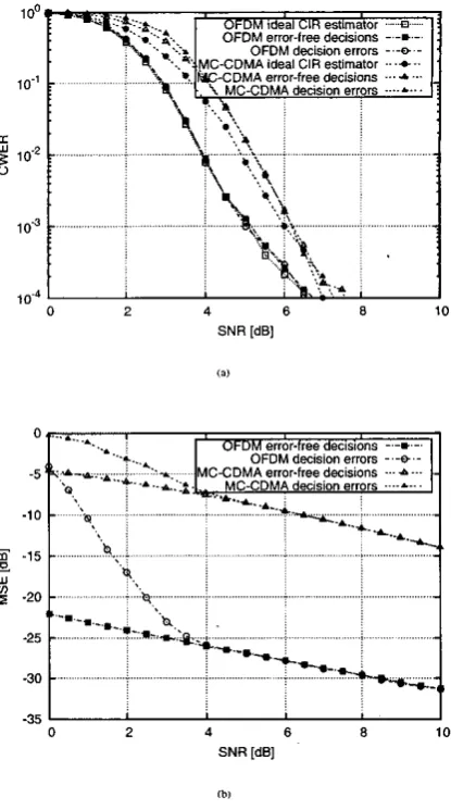
Flg. 2. la) CWER and lb) MSE of lhe QPSK-modulrtd OFDM and MC-CDMA ~ y s - tem wilh DDCEvndroburr timmedomUn predictmudcrmtcbed Doppler PSDcondiilons having r OFDM-symbol n a d i s e d Doppler frequency of f d T =0.01. We assume here having an infinite rimedomain interleaver. which is quimknr to having a constant overall channel ourput energy.
B. Performance Results
Figure 2 demonstntes (a) the achievable turbo-coded Code-Word Er-
ror Rate (CWER), where a Code-Word corresponds to a single turbo- coded OFDMIMC-CDMA symbol, and @) the MSE perfomwnce of the channel estimator far both the OFDM and the MC-CDMA systems considered under matched time-domain channel correlation conditions. Thus, the Doppler frequency assumed in the design of the robust CIR predictor matches the aCNd Doppler frequency of the lakes-correlated Rayleigh fading channel. The channel estimator featured employs the
c( posteriori FS-CIR estimator of Section Ill-A followed by the robust
U priori CIR predictor , a depicted in Figure 1. The simulations were canied out over the period of 100,ooO QPSK-modulated K = 128-
'We now dlt in pmia Uur mnditim CBnm h e n t i n e d Hwwer, !Mi arrumpia a,lowed YS
IO svow ul.l ulc pcrt""cc h d0rm"med by i " S l m C e L when M OFDM
*",
w u -i"d at a low0 2 4 6 8 10 SNR IdEl
18,
OFDM 0.03.0.01 - - - %...
OFDM 0.03.0.003 ...- a-..- OFDM 0.03,O.WI
-35
L
I
0 2 4 6 8 10
SNR IdEl
[image:5.614.97.309.77.450.2]l b l
Fig. 3. (a) CWER and (b) MSE of the QPSK-modulated OFDM system w i L DDCE and robust timedomain p d c l o r under "niched Doppler PSD condirioor having OFDM- symbol n o r d i s e d Doppler frequencies of f d T = 0.03 and 0.003 rssvmed during Le desi@ of the predicror, while the rcmd OFDM-symbol normalised Doppler frequencies encountered where fd?' = 0.03,0.01,0.003 ad 0.001. "he '%deal CIR entimami'
CUM in plot (a) conesponds to the OFDM system perionrrvlce under the assumpYon of perfect CIR bowledge.
subcanier OFDMIMC-CDMA symbols. It can be seen in Figure Xa).
that the performance of the channel estimator evaluated in the OFDM mode is close 10 that of the ideal estimator assuming perfect knowl- edge of the CIR. More explicitly, at low SNR values the achievable p e r f o m c e is degraded by the associated decision-error propagation, however the decision process becomes reliable for SNRs in excess of 4 ds.
In the MC-CDMA mode a 128-chip WH spreading code was as- sumed and a single user u a " i t t e d all the spreading codes in panllel in order to mainrain a data-rate similar to that of the OFDM system. All uansmined codes experienced the same SNR value. As seen in Figure 2, the MC-CDMA mode suffers from an
S N R
performance degrada- tion of about IdB
even under the assumption of a perfect CIR knowl-edge. Thisdegradationis inflictedmainly by the associated sub-optimal MMSE multi-code detection process [I]. The channel estimator im- poses a further slight SNR degradation of about 0.3
dB
on the MC- CDMA mode as a result of the Rayleigh-like energy disuibution of the transmitted frequency-domain subcarriers x [ n , k ] wiihin'each OFDM symbol, which m employed in the CIR estimator of Section Ill-A. By contrast. in the QPSK-modulated OFDM mode the energy of the uans- mitted frequency-domain samples z[n, k ] remains consmt.Finally, Figure 3 depicts (a) the CWER and (b) the MSE perfor- mance of the channel estimator in the context of an OFDM system un- der unmatched time-domain channel correlation conditions. Our simu- lations were performed for WO different values of the OFDM-symbol normalised Doppler frequency ?sumed during the design of the m- bust
C R
predictor, namely for f d T = 0.03 and 0.003. Furthermore, four different values of the actual normalised Doppler frequencies were used, namely j d T = 0.03,0.01,0.003 and 0.001. It can be seen that the performance of the CIR predictor advocated is indeed tolerant to the mismatch of the actual Doppler frequency and that assumed during the predictor design, as long as the actual Doppler frequency does not exceed the value assumed in the predictor's design.V. SUMMARY
In this paper we have proposed a channel estimation method, which is based on
a
low-complexity decision directed MMSE FS-CLR estima- tor combined with a robust time-domain FS-CIR predictor. We have found that the method proposed i s effective in both WSS channels as- sociated with a constant power intensity profile (PIP) and in channels having time-variant PIP. In the case of constant P P the knowledge ofthe channel's correlation properties can be exploited by the receiver for increasing the accuracy of the channel estimation process.
REFERENCES
Ill
[I]
131
L. H ~ o . M ~ l l r . 8. choi.andT. Krllrr. O ~ ~ M l m d M C - C D M A f o r B m o d b o n d Mul!;-u5~rCom-
muniror;onr WUNrmdBmodcasnhg. J h M l e y - I E E E R e s s . 2033.
A. FolbdUI. S. lafar. N. Jinw. and S. Mshwmth. 'Cr@Ci S d l l of MlMO rhnnnek:" IEEE Joiimol on Sdrrieddlrrrix !n Communicononr. VOI. 21. w. -702, JYW 2W3
Y. Li. 'TimpMsd c h d crtimtim lor O m M sysIlmr wlh multiplc mdc ante-," lEEE
Tmnacr;ms on \Vlwks Communlraiions. wl. I, w. 61-15. J m w y 2W2.
W i l r y b S m % 2 d c d . . Iw9.
cq Y. L;. L. cimilu. and N. ~aii~~ma. -R&X .hnl~ri =timation fa o m M I ) . s ~ , rim wd
tn
s. my, ~ ~~ f s ~ o ~ ; s ~ ~ c ~ i ~sj8na! ~ d ~ ~ ~c m . NI. ~~USA: ~lntia-mi. ~~ r ~ ~ t ~ ~. ~ ~ i l l R. Sick md L. Huua. c a . . Mobiis Rodic Conmiuniro?banr. Ncu Y d . US*: IEEE CTes - l o b[Si W. bkes P. d.. Mlrmwovr Mebilr Coamunirmrioonr. New Y&, USA: John WWy 8- S a x 1974.
dhpcnivc r u n g c ~ h : ' IEEE Tmnmir;m on Communlrdons. vol. 45 pp. 902-91S. A w l 1998.
1998.
S. L. M u p k Digbdspeccrml m d # s M h oppkonons. E n g l r m d Cliffs, NI, US& Roulcr H 1 ,
1987.
[81